EP1445232B1 - Fahrzeugaufhängevorrichtung - Google Patents
Fahrzeugaufhängevorrichtung Download PDFInfo
- Publication number
- EP1445232B1 EP1445232B1 EP03250859A EP03250859A EP1445232B1 EP 1445232 B1 EP1445232 B1 EP 1445232B1 EP 03250859 A EP03250859 A EP 03250859A EP 03250859 A EP03250859 A EP 03250859A EP 1445232 B1 EP1445232 B1 EP 1445232B1
- Authority
- EP
- European Patent Office
- Prior art keywords
- axle
- articulation
- range
- vehicle frame
- suspension system
- Prior art date
- Legal status (The legal status is an assumption and is not a legal conclusion. Google has not performed a legal analysis and makes no representation as to the accuracy of the status listed.)
- Expired - Lifetime
Links
- 239000000725 suspension Substances 0.000 title claims description 31
- 238000000034 method Methods 0.000 claims description 7
- 230000006835 compression Effects 0.000 claims description 5
- 238000007906 compression Methods 0.000 claims description 5
- 238000006073 displacement reaction Methods 0.000 claims description 5
- 230000008878 coupling Effects 0.000 claims 2
- 238000010168 coupling process Methods 0.000 claims 2
- 238000005859 coupling reaction Methods 0.000 claims 2
- 230000001737 promoting effect Effects 0.000 claims 1
- 238000005266 casting Methods 0.000 description 5
- 239000013536 elastomeric material Substances 0.000 description 2
- 230000007704 transition Effects 0.000 description 2
- 239000013013 elastic material Substances 0.000 description 1
Images



Classifications
-
- B—PERFORMING OPERATIONS; TRANSPORTING
- B60—VEHICLES IN GENERAL
- B60G—VEHICLE SUSPENSION ARRANGEMENTS
- B60G9/00—Resilient suspensions of a rigid axle or axle housing for two or more wheels
- B60G9/02—Resilient suspensions of a rigid axle or axle housing for two or more wheels the axle or housing being pivotally mounted on the vehicle, e.g. the pivotal axis being parallel to the longitudinal axis of the vehicle
-
- B—PERFORMING OPERATIONS; TRANSPORTING
- B66—HOISTING; LIFTING; HAULING
- B66F—HOISTING, LIFTING, HAULING OR PUSHING, NOT OTHERWISE PROVIDED FOR, e.g. DEVICES WHICH APPLY A LIFTING OR PUSHING FORCE DIRECTLY TO THE SURFACE OF A LOAD
- B66F9/00—Devices for lifting or lowering bulky or heavy goods for loading or unloading purposes
- B66F9/06—Devices for lifting or lowering bulky or heavy goods for loading or unloading purposes movable, with their loads, on wheels or the like, e.g. fork-lift trucks
- B66F9/075—Constructional features or details
- B66F9/07586—Suspension or mounting of wheels on chassis
Definitions
- FIG. 1 shows a conventional lift truck 10 such as disclosed in US-A-3,480,100 , whose basic function of lifting and transporting cargo is well-known.
- Drive wheels 12 are connected to a drive axle (not shown) and steer wheels 14 are connected to a steer axle 20 shown in FIG. 2 .
- the drive axle is rigidly connected to the frame of lift truck 10.
- the steer axle 20 is used for steering the truck 10 and includes a suspension system on which the precharacterising portion of claim 1 is based and which is shown in more detail in FIG. 2 .
- FIG. 2 is a top-view of the steer axle 20 used in the lift truck 10 shown in FIG. 1 .
- the rear wheels 14 are attached to opposite ends of the steer axle 20.
- Stubs 20A and 20B extend from the opposite back and front ends, respectively, of the steer axle 20.
- a pair of brackets 22A and 22B are bolted to the truck frame 24 and hold the stubs 20A and 20B, respectively.
- FIG. 3 is a rear sectional view of the steer axle 20. From this view, only bracket 22A is shown. Bracket 22B is similar to bracket 22A. The stub 20A of the steer axle 20 is centered about a center point 21. The stub 20A is held in substantially the same relative position within the bracket 22A about center point 21 by a rubber bushing 30. The rubber bushing 30 allows the steer axle 20 to pivot about the center point 21 when the steer axle 20 articulates (laterally inclines) either clockwise or counter clockwise.
- Two articulation stops 32A and 32B are located on the upper surface of the steer axle 20.
- the spaces between the articulation stops 32A and 32B and the truck frame 24 are referred to as articulation gaps 34A and 34B, respectively.
- articulation gaps 34A and 34B When the lift truck 10 is at rest, or traveling in a straight line on level terrain 31, there is little articulation of the steer axle 20 and the articulation gaps 34A and 34B remain relatively constant.
- steer axle 20 is free to pivot about center point 21 independently of the frame 24. This pivoting of steer axle 20 allows the lift truck 10 to maneuver over uneven terrain and obstacles, or make turns, without effecting the lateral displacement of the frame 24.
- the size of the articulation gaps 34A and 34B determine how far the steer axle 20 can articulate without laterally displacing the frame 24. If the steer axle 20 articulates far enough on one side, one of the articulation stops 32A or 32B contacts frame 24. In this articulation stop contact position, any further lateral articulation of the steer axle 20 equally articulates the frame 24.
- Larger articulation gaps 34A and 34B can increase how much the steer axle 20 can articulate before one of the articulation stops 32A and 32B contacts frame 24. Larger articulation gaps 34A and 34B allow more articulation of the steer axle 20 without laterally displacing the frame 24.
- FIG. 4 shows stability profiles for the suspension system shown in FIGS. 2 and 3 .
- the lift truck 10 has a triangular stability profile RSU when the articulation stops 32A and 32B ( FIG. 3 ) are not contacting the truck frame 24. With the triangular stability profile RSU, the lift truck frame 24 is supported at the R and S locations of drive tires 12 and at a U location along the centerline of the steer axle 20.
- the lift truck 10 changes to more of a rectangular shaped stability profile RSTV when either of the articulation stops 32A or 32B come in contact with the frame 24.
- the steer axle 20 pivots sufficiently to contact either one of the articulation stops 32A or 32B ( FIG. 3 )
- the steer axle 20 moves into a rigid non-pivoting relationship with the frame 24. This moves the lateral support locations for the rear end of frame 24 from centerline location U out to the T and V locations at the rear wheels 14.
- the present invention provides a vehicle suspension system as defined in claim 1 and a method of providing a vehicle-suspension as defined in claim 17.
- FIG. 5 shows a suspension system 15 that includes a bracket 22A rigidly connected to the truck frame 24.
- the bracket 22A contains a rubber bushing 50 having a hole 23 that receives the steer axle stub 20A previously shown in FIG. 2 .
- a similar bushing 50 is also located at the front end of the steer axle 20 contained in the bracket 22B shown in FIG. 2 .
- bushings 50 promotes vertical compression or vertical movement of the bushing 50 when sufficient downward force is applied by the stub 20A.
- the shape of bushing 50 forms cavities 52A and 52B between the bushing 50 and bracket 22A.
- the bushing 50 forms a concave spacing 52A in the bottom of bracket 22A and lateral spaces 52B on the sides of bracket 22A.
- other bushing shapes can also be used that allow a vertical downward compression.
- Different types of elastomeric material can be used for the bushings 50.
- FIG. 6 shows a rear view of the steer axle 20 while the tire for left steer wheel 14 traverses over an object 55. As the tire rolls over the object 55, the steer axle 20 pivots in a clockwise direction about the center point 25 previously shown in FIG. 5 . The clockwise pivoting of the steer axle 20 moves the articulation stop 32A into contact with the frame 24.
- the left end of rigid steer axle 20 continues to move upward after articulation stop 32A contacts frame 24. This causes the stub 20A to compress bushing 50 downward.
- the steer axle 20 in this condition pivots about articulation stop 32A at location W.
- the downward movement of the stub 20A moves the bushing 50 downward partially filling in gaps 52A and 52B ( FIG. 5 ).
- the center point of stubs 20A and 20B move vertically downward from location 25 to location 27.
- the pivot point of the steer axle 20 effectively moves laterally out from center line y to the articulation stop 32A at location W.
- the steer axle 20 may continue to articulate until a bottom end 53 and sides 57 of the rubber bushing 50 fill in a certain portion of the gaps 52A and 52B ( FIG.5 ). In this fully compressed state, the steer axle 20 and the frame 24 move into a semi-rigid fixed relationship with each other. Any additional articulation of the steer axle 20 at this point also articulates the frame 24.
- rubber bushings or some other type of elastomeric material, can be located on the tops of the articulation stops 32A and 32B.
- springs can be located on the articulation stops 32A and 32B. The elastic material or springs dampen the forces applied by the articulation stops 32A and 32B when contacting frame 24.
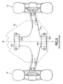
- FIG. 7 is a top view of the chassis for the lift truck 10 shown in FIG. 1 that uses the suspension system 15 previously shown in FIGS. 5 and 6 .
- the drive wheels 12 are attached to the drive axle 40 and the steer wheels 14 are attached to the steer axle 20.
- the drive axle 40 is rigidly affixed to frame 24 and does not pivot independently with respect to frame 24.
- the steer axle 20 pivots about the frame centerline AB in a first articulation range prior to one of the articulation stops 32A or 32B ( FIG. 5 ) contacting frame 24.
- the lift truck has the triangular stability profile RSV defined by the points R, S, and V.
- one of the articulation stops 32A or 32B contacts the frame 24 as previously shown in FIG. 6 . This may happen, for example, when the tire for one of the steer wheels 14 travels over an object.
- the lift truck 10 transitions from the triangular stability profile RSV to a trapezoidal stability profile RSUW corresponding to locations R, S, U, and W.
- the points R and S correspond to locations on the drive wheels 12.
- the locations W and U correspond to the locations where the articulation stops 32A and 32B, respectively, contact the frame 24.
- the steer axle stubs 20A and 20B start compressing bushing 50 in a downward direction as described above in FIG. 6 . This allows the steer axle 20 ( FIG. 6 ) to pivot about point W or point U.
- the pivot point of the steer axle 20 effectively moves from location V to location W or location U.
- the steer axle 20 still articulates semi-independently from the frame 24.
- This trapezoidal stability profile is caused by the vertical displacement of the stubs 20A and 20B inside of bushings 50 ( FIG. 6 ).
- the steer axle stubs 20A and 20B can no longer move downward in bushings 50.
- the gaps 52A and 52B FIG. 5
- the lift truck 10 transitions to a stability profile RSXT approaching a rectangular shape.
- the stability profile RSXT is larger than the trapezoidal stability profile RSWU and extends out to the wheels 12 and 14.
- any further lateral articulation of the steer axle 20 causes substantially the same amount of lateral articulation in frame 24.
- bushing 50 allows vertical displacement of the steer axle center pivot point.
- Other bushing shapes could also be used that enable a center pivot point of an axle to move vertically up and down.
- FIGS. 8A and 8B show an alternative embodiment that uses compression coil springs 82, 83, 84, and 85.
- the upper springs 82 and 84 are somewhat larger than the lower springs 83 and 85.
- a mounting bracket weldment 80 attaches the steer axle 20 to frame 24.
- a steer axle casting 88 is formed as part of the steer axle 20 or is a separate piece rigidly welded or bolted to the steer axle 20.
- the steer axle casting 88 includes T shaped posts 91 on opposite ends that insert inside of both the upper springs 82 and 84 and inside the lower springs 83 and 85.
- a rubber bushing 89 sits between the steer axle casting 88 and weldment 80. Washers 93 retain the rubber bushing 93 and protect the bushing 89 from the springs 82, 83, 84 and 85.
- the frame 24 is supported on the upper springs 82 and 84.
- the steer axle 20 rotates laterally about center line 90 and the articulation stops 32A and 32B do not contact frame 24. This produces a triangular stability profile similar to triangular stability profile RSV shown in FIG. 7 .
- the articulation stop 32A or 32B contacts frame 24 and combinations of the springs 82, 83, 84, and 85 continue to compress. This allows the steer axle casting 88 to continue to move in a downward direction in weldment 80.
- the steer axle 20 is allowed to pivot about the articulation stop 32A or 32B that contacts the frame 24 providing a trapezoidal stability profile similar to trapezoidal profile RSUW shown in FIG. 7 .
- the steer axle casting 88 fully compresses a combination of the springs 82, 83, 84, and 85.
- the steer axle 20 in this condition has a substantially rigid non-pivoting contact with frame 24.
- the suspension system in this state exhibits a larger stability profile approaching a rectangular shape similar to the stability profile RSXT shown in FIG. 7 .
- variable suspension profiles may be used for providing the variable suspension profiles shown above.
- a single traverse set of variable leaf springs that are stiffer in the upward direction than in the downward direction can be used to bridge the front and rear mounting locations of the steer axle 20.
- the leaf springs can bridge the locations where brackets 22A and 22B are located in FIG. 2 .
- Any other different combination of springs or bushings can also be used to vary the stability profiles of the lift truck as described above.
- FIGS. 5-7 The embodiment of the invention described in FIGS. 5-7 is a passive system. That is, the bushing 50 merely reacts to laterally applied forces.
- an active system may also be used to perform the same function.
- a hydraulic system may be used to directly raise or lower the center pivot point 25 ( FIG. 5 ) of the steer axle 20 according to sensor inputs.
- Active systems could also adaptively adjust a spring constant of the movable pivot point according to the weight of the load carried by the lift truck or the degree of lateral inclination of the lift truck.
Landscapes
- Engineering & Computer Science (AREA)
- Mechanical Engineering (AREA)
- Transportation (AREA)
- Structural Engineering (AREA)
- Civil Engineering (AREA)
- Life Sciences & Earth Sciences (AREA)
- Geology (AREA)
- Vehicle Body Suspensions (AREA)
- Forklifts And Lifting Vehicles (AREA)
- Body Structure For Vehicles (AREA)
Claims (22)
- Fahrzeugaufhängungssystem (15), welches umfasst:einen Fahrzeugrahmen (24);eine Achse (20); undeinen Befestigungsmechanismus (50, 22A,B; 80-93), welcher fest an einer Mittelachse des Fahrzeugrahmens (24) befestigt ist und die Achse (20) mit dem Fahrzeugrahmen (24) verbindet, so dass die Achse (20) bezüglich des Fahrzeugrahmens (24) um eine erste Position (25) schwenkt, wenn die Achse (20) in einem ersten Gelenkbereich arbeitet, dadurch gekennzeichnet, dass:der Befestigungsmechanismus (50, 22A,B; 80-93) so ausgelegt ist, dass die Achse (20) bezüglich des Fahrzeugrahmens (24) um eine der zwei zweiten Positionen (32A,B) schwenkt, wenn die Achse (20) in einem zweiten Gelenkbereich arbeitet, der größer als der erste Gelenkbereich ist, so dass die Achse (20) bezüglich des Fahrzeugrahmens (20) gemäß des Betrags der Winkelverschiebung der Achse (20) um verschiedene seitliche Positionen schwenkt.
- Fahrzeugaufhängungssystem (15) nach Anspruch 1, dadurch gekennzeichnet, dass die Achse (20) eine Lenkachse eines Lastkraftwagens umfasst.
- Fahrzeugaufhängungssystem (15) nach Anspruch 1 oder 2, welches auf gegenüberliegenden Seiten der Achse (20) befindliche Gelenkanschläge (32A,B) umfasst, von denen jeder eine Gelenklücke mit dem Fahrzeugrahmen (24) aufrecht erhält, wenn die Achse in dem ersten Gelenkbereich arbeitet.
- Fahrzeugaufhängungssystem (15) nach Anspruch 3, dadurch gekennzeichnet, dass sich die erste Position auf einer ersten Mittelachse der Achse (20) befindet und die zweiten Positionen jeweils die Gelenkanschläge (32A,B) umfassen, wobei der zweite Gelenkbereich ist, wenn einer der Gelenkanschläge (32A,B) den Fahrzeugrahmen (24) berührt.
- Fahrzeugaufhängungssystem (15) nach Anspruch 4, dadurch gekennzeichnet, dass der Befestigungsmechanismus (50, 22A,B; 80-93) ein weiteres Schwenken der Achse (20) um den berührenden Gelenkanschlag (35A,B) verhindert, wenn die Achse (20) in einem dritten Gelenkbereich arbeitet, der größer als der zweite Gelenkbereich ist.
- Fahrzeugaufhängungssystem (15) nach Anspruch 5, dadurch gekennzeichnet, dass der Befestigungsmechanismus (50, 22A,B; 80-93) einen Gelenkanschlag (32A,B) auf der Achse (20) in im Wesentlichen festem, nicht schwenkendem Kontakt mit dem Fahrzeugrahmen (24) erhält, nachdem die Achse einen vorgegebenen Neigungsbereich überschreitet.
- Fahrzeugaufhängungssystem (15) nach einem der Ansprüche 1 bis 6, dadurch gekennzeichnet, dass der Befestigungsmechanismus (50, 22A,B) eine Achsenverlängerung (20A, 20B) festhält und ein Bewegen der Achsenverlängerung (20A, 20B) vertikal nach oben und nach unten in dem Befestigungsmechanismus (50, 22A,B; 80-93) in dem zweiten Gelenkbereich der Achse (20) zulässt.
- Fahrzeugaufhängungssystem (15) nach einem der vorstehenden Ansprüche, dadurch gekennzeichnet, dass der Befestigungsmechanismus (50, 22A,B; 80-93) eine Seitenbewegung eines Achsenmittelpunkts (25) bezüglich des Fahrzeugrahmens (24) einschränkt, während er eine vertikale Bewegung des Achsenmittelpunkts (25) bezüglich des Fahrzeugrahmens (24) zulässt.
- Fahrzeugaufhängungssystem (15) nach Anspruch 7 oder 8, dadurch gekennzeichnet, dass der Befestigungsmechanismus (50, 22A,B; 80-93) eine Gummibuchse (50, 89) umfasst.
- Fahrzeugaufhängungssystem (15) nach Anspruch 7, 8 oder 9, dadurch gekennzeichnet, dass der Befestigungsmechanismus (50, 22A,B; 80-93) Federn (82-85) umfasst.
- Fahrzeugaufhängungssystem (15) nach Anspruch 7 oder 8, dadurch gekennzeichnet, dass der Befestigungsmechanismus (50, 22A,B; 80-93) eine Elastomerbuchse (50) umfasst.
- Fahrzeugaufhängungssystem (15) nach Anspruch 11, dadurch gekennzeichnet, dass die Buchse (50) Hohlräume (52A, B) umfasst, die in einem unteren Ende zum Fördern vertikaler Kompression ausgebildet sind.
- Fahrzeugaufhängungssystem (15) nach Anspruch 11 oder 12, dadurch gekennzeichnet, dass die Buchse (50) aus einem einzigen Stück Gummi mit einem Mittelloch (23) zum Aufnehmen einer Achsenverlängerung (20A, 20B) ausgebildet ist, wobei die Buchse (50) zulässt, dass sich die Achsenverlängerung (20A, 20B) um eine Mittelachse (25) dreht und sich auch vertikal nach unten bewegt, wenn durch die Achsenverlängerung (20A, 20B) eine ausreichende Abwärtskraft ausgeübt wird.
- Fahrzeugaufhängungssystem (15) nach Anspruch 7 oder 8, dadurch gekennzeichnet, dass der Befestigungsmechanismus (50, 22A,B; 80-93) Federn (82-85) umfasst, die eine mittlere Verlängerung (88) der Achse (20) halten.
- Fahrzeugaufhängungssystem (15) nach einem der vorstehenden Ansprüche, dadurch gekennzeichnet, dass der Fahrzeugrahmen (24) ein dreieckiges Stabilitätsprofil erzeugt, wenn die Achse (20) sich in einem ersten Gelenkbereich befindet, ein trapezförmiges Stabilitätsprofil erzeugt, wenn die Achse (20) sich in einem zweiten Gelenkbereich befindet, und ein drittes größeres Stabilitätsprofil erzeugt, welches sich an eine rechteckige Form annähert, wenn die Achse (20) sich in einem dritten Gelenkbereich befindet.
- Fahrzeugaufhängungssystem (15) nach einem der vorstehenden Ansprüche, dadurch gekennzeichnet, dass die Kompression in dem Befestigungsmechanismus (50, 22A,B; 80-93) eine vertikale Bewegung der Achse (24) in dem zweiten Gelenkbereich der Achse (20) vorsieht.
- Verfahren zum Vorsehen einer Fahrzeugaufhängung, welches umfasst:Verbinden einer Achse (20) mit einem Fahrzeugrahmen (24), so dass die Achse (20) bezüglich des Fahrzeugrahmens (24) um eine erste Position (25) schwenkt, wenn die Achse (20) in einem ersten Gelenkbereich arbeitet, dadurch gekennzeichnet, dass die Achse (20) bezüglich des Fahrzeugrahmens (20) um eine von zwei zweiten Positionen (32A,B) schwenkt, die seitlich auf gegenüberliegenden Seiten der ersten Position (25) voneinander beabstandet sind, wenn die Achse (20) in einem zweiten Gelenkbereich arbeitet, der größer als der erste Gelenkbereich ist, so dass die Achse (20) gemäß des Betrags der Winkelverschiebung der Achse (20) bezüglich des Fahrzeugrahmens (24) um verschiedene seitliche Positionen schwenkt.
- Verfahren nach Anspruch 17, welches das Vorsehen eines ersten Stabilitätsprofils bei Schwenken der Achse (20) um die erste Position (25), eines zweiten größeren Stabilitätsprofils bei Schwenken der Achse (20) um die zweiten Positionen (32A,B) und des Vorsehens eines dritten Stabilitätsprofils, welches größer als das zweite Stabilitätsprofil ist, wenn die Achse (20) einen dritten Gelenkbereich aufweist, der größer als der zweite Gelenkbereich ist, umfasst.
- Verfahren nach Anspruch 17 oder 18, welches das Schwenken der Achse (20) ungefähr um eine Mittellinie eines Fahrzeugrahmens (24), wenn die Achse (20) in dem ersten Gelenkbereich arbeitet, und das Bewegen der Achse (20) vertikal nach oben und unten an der ersten Position (25), wenn die Achse (20) in dem zweiten Gelenkbereich arbeitet, umfasst.
- Verfahren nach Anspruch 17, 18 oder 19, welches das Schwenken der Achse (20) ungefähr um einen Gelenkanschlag (32A,B), der den Fahrzeugrahmen (24) berührt, wenn die Achse (20) in dem zweiten Gelenkbereich arbeitet, umfasst.
- Verfahren nach Anspruch 17, 18, 19 oder 20, welches bei Arbeiten der Achse (20) in dem ersten Gelenkbereich das Halten einer mittleren Position (25) der Achse (20) bei im Wesentlichen einem gleichen Abstand von dem Fahrzeugrahmen (24) und bei Arbeiten in dem zweiten Gelenkbereich das Ermöglichen, dass sich die mittlere Position (25) der Achse verändert oder sich vertikal weg von dem Fahrzeugrahmen (24) bewegt, umfasst.
- Verfahren nach Anspruch 21, welches bei Arbeiten der Achse (20) in einem dritten Gelenkbereich, der größer als der zweite Gelenkbereich ist, das Halten der Achse (20) in einem im Wesentlichen festen Kontakt mit dem Fahrzeugrahmen (24) umfasst.
Applications Claiming Priority (2)
| Application Number | Priority Date | Filing Date | Title |
|---|---|---|---|
| US10/318,434 US6959936B2 (en) | 2002-12-13 | 2002-12-13 | Vehicle suspension system |
| US318434 | 2002-12-13 |
Publications (2)
| Publication Number | Publication Date |
|---|---|
| EP1445232A1 EP1445232A1 (de) | 2004-08-11 |
| EP1445232B1 true EP1445232B1 (de) | 2009-07-22 |
Family
ID=32506337
Family Applications (1)
| Application Number | Title | Priority Date | Filing Date |
|---|---|---|---|
| EP03250859A Expired - Lifetime EP1445232B1 (de) | 2002-12-13 | 2003-02-12 | Fahrzeugaufhängevorrichtung |
Country Status (5)
| Country | Link |
|---|---|
| US (1) | US6959936B2 (de) |
| EP (1) | EP1445232B1 (de) |
| JP (1) | JP3771550B2 (de) |
| DE (1) | DE60328453D1 (de) |
| ES (1) | ES2328681T3 (de) |
Families Citing this family (18)
| Publication number | Priority date | Publication date | Assignee | Title |
|---|---|---|---|---|
| US7740084B2 (en) | 2000-05-02 | 2010-06-22 | Lyn Rosenboom | Agricultural implement frame, track assembly and cart |
| US7726749B2 (en) * | 2001-05-02 | 2010-06-01 | Lyn Rosenboom | Track assembly with bogie wheel structure |
| US7380892B2 (en) * | 2001-05-02 | 2008-06-03 | Lyn Rosenboom | Track assembly with idler wheels and cart incorporating same |
| US8658554B2 (en) | 2009-11-04 | 2014-02-25 | The United States Of America, As Represented By The Secretary Of The Navy | Catalytic support for use in carbon dioxide hydrogenation reactions |
| CA2744630C (en) | 2010-06-30 | 2018-10-09 | Camoplast Solideal Inc. | Wheel of a track assembly of a tracked vehicle |
| KR101620823B1 (ko) * | 2010-08-02 | 2016-05-12 | 주식회사 두산 | 중장비의 스티어 액슬 어세이 장착구조 |
| US9505454B1 (en) | 2011-06-13 | 2016-11-29 | Camso Inc. | Track assembly for traction of an off-road vehicle |
| US8962702B2 (en) | 2011-12-08 | 2015-02-24 | Saudi Basic Industries Corporation | Mixed oxide based catalyst for the conversion of carbon dioxide to syngas and method of preparation and use |
| US8551434B1 (en) | 2012-06-29 | 2013-10-08 | Saudi Basic Industries Corporation | Method of forming a syngas mixture |
| WO2015066117A1 (en) | 2013-10-29 | 2015-05-07 | Saudi Basic Industries Corporation | Method for carbon dioxide hydrogenation of syngas and the integration of the process with syngas conversion processes |
| CN105899648A (zh) | 2014-01-06 | 2016-08-24 | 沙特基础工业公司 | 用于合成气的二氧化碳氢化的方法 |
| US10875591B2 (en) | 2015-08-04 | 2020-12-29 | Camso Inc. | Track system for traction of an agricultural vehicle travelling on fields and roads |
| US10525783B1 (en) * | 2015-10-21 | 2020-01-07 | Rf Products, Inc. | Suspension system |
| JP6754630B2 (ja) * | 2016-06-27 | 2020-09-16 | 株式会社クボタ | 車軸装置 |
| DE102017221375A1 (de) * | 2017-11-29 | 2019-05-29 | Zf Friedrichshafen Ag | Flurförderfahrzeug mit einer Pendelachse |
| US11597638B2 (en) * | 2019-04-05 | 2023-03-07 | Oshkosh Corporation | Oscillating axle for lift device |
| US11383570B2 (en) * | 2019-12-23 | 2022-07-12 | The Raymond Corporation | Systems and methods for a material handling vehicle with an articulating axle |
| US11607910B1 (en) * | 2022-03-01 | 2023-03-21 | Caterpillar Inc. | Axle oscillation stop for construction machine |
Family Cites Families (31)
| Publication number | Priority date | Publication date | Assignee | Title |
|---|---|---|---|---|
| US1120036A (en) | 1913-01-16 | 1914-12-08 | David M Dearing | Running-gear for motor-vehicles. |
| US1164925A (en) * | 1914-11-11 | 1915-12-21 | Clark E Clapp | Automobile attachment. |
| DE870503C (de) * | 1940-06-07 | 1953-03-16 | Daimler Benz Ag | Kraftfahrzeug, insbesondere mit Schwinghalbachsen |
| DE872007C (de) * | 1940-06-19 | 1953-03-26 | Daimler Benz Ag | Nachgiebige Verbindung eines Achsaggregates mit dem Rahmen oder Fahrzeugoberbau |
| US2835507A (en) | 1955-06-07 | 1958-05-20 | Otis Elevator Co | Axle mounting for a vehicle |
| US2978050A (en) * | 1958-10-28 | 1961-04-04 | Caterpillar Tractor Co | Front end suspension for tractors |
| US3738665A (en) * | 1972-01-03 | 1973-06-12 | Raymond Corp | Hydraulic seals |
| US3778080A (en) * | 1972-05-15 | 1973-12-11 | Raymond Corp | Lift truck load wheel arrangement |
| US3872941A (en) | 1974-01-23 | 1975-03-25 | Caterpillar Tractor Co | Equalizer bar oscillation stop and protective guard |
| US3929346A (en) | 1974-04-17 | 1975-12-30 | Eaton Corp | Steering axle assembly providing improved lateral stability |
| JPS5849432A (ja) | 1981-07-21 | 1983-03-23 | フオスタ−・ホイ−ラ−・エナ−ジイ・コ−ポレイシヨン | 流動床式反応器 |
| JPS58218408A (ja) | 1982-06-12 | 1983-12-19 | Nissan Motor Co Ltd | 自動車のリアサスペンシヨン装置 |
| JPS60124512A (ja) | 1983-12-08 | 1985-07-03 | Toyoda Autom Loom Works Ltd | フォ−クリフトトラックの懸架装置 |
| IT1180109B (it) * | 1984-11-05 | 1987-09-23 | Roberto Perlini | Sistema di ancoraggio di assali di veicoli con sospensioni a corsa verticale impiegante giunti rototraslatori |
| JPS61179009A (ja) | 1985-01-31 | 1986-08-11 | 日本特殊陶業株式会社 | 高周波誘電体磁器 |
| US4721187A (en) * | 1987-03-23 | 1988-01-26 | The Raymond Corporation | Lift truck mast structure |
| US4754837A (en) * | 1987-04-30 | 1988-07-05 | The Raymond Corporation | Lift truck steering apparatus |
| US4813512A (en) * | 1987-06-15 | 1989-03-21 | The Raymond Corporation | Idler wheel assemblies |
| SU1530519A2 (ru) * | 1988-03-09 | 1989-12-23 | Всесоюзный Научно-Исследовательский Институт Коневодства | Одноконна повозка |
| JPH0373597A (ja) | 1989-08-15 | 1991-03-28 | Nippon Telegr & Teleph Corp <Ntt> | 電子機器温度均一装置 |
| JPH03193515A (ja) | 1989-12-22 | 1991-08-23 | Toyota Autom Loom Works Ltd | 産業車両におけるアクスルビームの懸架装置 |
| US5039924A (en) * | 1990-05-07 | 1991-08-13 | Raymond Corporation | Traction motor optimizing system for forklift vehicles |
| US5070283A (en) * | 1990-05-07 | 1991-12-03 | Raymond | Traction motor controller for forklift vehicles |
| US5123081A (en) * | 1990-07-27 | 1992-06-16 | Raymond Corporation | Temperature control system for motors and power components of a material handling vehicle |
| US5113344A (en) * | 1990-07-27 | 1992-05-12 | Raymond Corporation | Material handling vehicle identification tag |
| JPH04339005A (ja) | 1991-05-14 | 1992-11-26 | Toyota Autom Loom Works Ltd | リヤアクスルビームの取付装置 |
| USD335741S (en) * | 1991-09-09 | 1993-05-18 | Raymond Corporation | Control handle for a material handling vehicle |
| JP3109280B2 (ja) | 1992-09-30 | 2000-11-13 | 日産自動車株式会社 | 後輪操舵車両における揺動制御構造 |
| KR0166131B1 (ko) * | 1994-12-30 | 1998-12-01 | 석진철 | 지게차의 유압회로 |
| IT1291750B1 (it) * | 1997-05-16 | 1999-01-21 | Clark Hurth Components Spa | Struttura di sospensione elastica per assali di veicoli industriali e simili |
| ES2215846T3 (es) * | 2001-01-26 | 2004-10-16 | Dana Italia S.P.A | Eje suspendido del tipo de conexion articulada para vehiculos industriales. |
-
2002
- 2002-12-13 US US10/318,434 patent/US6959936B2/en not_active Expired - Lifetime
-
2003
- 2003-02-12 ES ES03250859T patent/ES2328681T3/es not_active Expired - Lifetime
- 2003-02-12 EP EP03250859A patent/EP1445232B1/de not_active Expired - Lifetime
- 2003-02-12 DE DE60328453T patent/DE60328453D1/de not_active Expired - Lifetime
- 2003-08-27 JP JP2003209047A patent/JP3771550B2/ja not_active Expired - Lifetime
Also Published As
| Publication number | Publication date |
|---|---|
| DE60328453D1 (de) | 2009-09-03 |
| EP1445232A1 (de) | 2004-08-11 |
| JP2004196284A (ja) | 2004-07-15 |
| ES2328681T3 (es) | 2009-11-17 |
| US20040113383A1 (en) | 2004-06-17 |
| US6959936B2 (en) | 2005-11-01 |
| JP3771550B2 (ja) | 2006-04-26 |
Similar Documents
| Publication | Publication Date | Title |
|---|---|---|
| EP1445232A1 (de) | Fahrzeugaufhängevorrichtung | |
| US5882031A (en) | Vehicle suspension system | |
| US5505482A (en) | Road-railer suspension system having a spring lift and a stabilizer bar | |
| EP0716942B1 (de) | Aufhängungssystem zur Steuerung der seitlichen Verlagerung eines Rades | |
| CA2240791A1 (en) | Trailing arm suspension | |
| WO2003059663A1 (en) | Anti-roll vehicle suspension | |
| EP1972471B1 (de) | Aktives Achsenaufhängungssystem | |
| US3807752A (en) | Vehicle wheel support | |
| US20030116935A1 (en) | Anti-roll vehicle suspension | |
| US4815756A (en) | Terrain vehicle stabilizer | |
| US6250660B1 (en) | Camber angle control suspension system | |
| CA2578776A1 (en) | Vehicle suspension system | |
| JP2005506922A (ja) | 車両のホイール・アッセンブリを懸架するための方法及び装置 | |
| EP0287094B1 (de) | Hintere Radaufhängung für ein Kraftfahrzeug | |
| JP3109280B2 (ja) | 後輪操舵車両における揺動制御構造 | |
| JP2000515460A (ja) | 車両のリジッドアクスルのためのアクスルサスペンション | |
| CA1194842A (en) | Industrial truck | |
| KR200371807Y1 (ko) | 대형차량용 에어서스펜션장착차축의 역캐스터구조 | |
| KR100797560B1 (ko) | 대형차량용 리어에어서스펜션의 캐스터 조절장치 | |
| EP1046520B1 (de) | Aufhängungsanschlag für ein landwirtschaftliches Fahrzeug | |
| KR20200084235A (ko) | 트럭의 보조바퀴 승강장치 | |
| CN211809914U (zh) | 车辆底盘边缘式支撑装置 | |
| KR200260742Y1 (ko) | 자동차용 차축 현가 장치 | |
| KR100649964B1 (ko) | 지오메트리 컨트롤 조인트 | |
| US3929346A (en) | Steering axle assembly providing improved lateral stability |
Legal Events
| Date | Code | Title | Description |
|---|---|---|---|
| PUAI | Public reference made under article 153(3) epc to a published international application that has entered the european phase |
Free format text: ORIGINAL CODE: 0009012 |
|
| AK | Designated contracting states |
Kind code of ref document: A1 Designated state(s): AT BE BG CH CY CZ DE DK EE ES FI FR GB GR HU IE IT LI LU MC NL PT SE SI SK TR |
|
| AX | Request for extension of the european patent |
Extension state: AL LT LV MK RO |
|
| 17P | Request for examination filed |
Effective date: 20041103 |
|
| AKX | Designation fees paid |
Designated state(s): AT BE BG CH CY CZ DE DK EE ES FI FR GB GR HU IE IT LI LU MC NL PT SE SI SK TR |
|
| RAP1 | Party data changed (applicant data changed or rights of an application transferred) |
Owner name: NACCO MATERIALS HANDLING GROUP, INC. |
|
| 17Q | First examination report despatched |
Effective date: 20060912 |
|
| GRAP | Despatch of communication of intention to grant a patent |
Free format text: ORIGINAL CODE: EPIDOSNIGR1 |
|
| GRAS | Grant fee paid |
Free format text: ORIGINAL CODE: EPIDOSNIGR3 |
|
| GRAA | (expected) grant |
Free format text: ORIGINAL CODE: 0009210 |
|
| RAP1 | Party data changed (applicant data changed or rights of an application transferred) |
Owner name: NACCO MATERIALS HANDLING GROUP, INC. |
|
| AK | Designated contracting states |
Kind code of ref document: B1 Designated state(s): AT BE BG CH CY CZ DE DK EE ES FI FR GB GR HU IE IT LI LU MC NL PT SE SI SK TR |
|
| REG | Reference to a national code |
Ref country code: GB Ref legal event code: FG4D |
|
| REG | Reference to a national code |
Ref country code: CH Ref legal event code: EP |
|
| REG | Reference to a national code |
Ref country code: IE Ref legal event code: FG4D |
|
| REF | Corresponds to: |
Ref document number: 60328453 Country of ref document: DE Date of ref document: 20090903 Kind code of ref document: P |
|
| REG | Reference to a national code |
Ref country code: ES Ref legal event code: FG2A Ref document number: 2328681 Country of ref document: ES Kind code of ref document: T3 |
|
| PG25 | Lapsed in a contracting state [announced via postgrant information from national office to epo] |
Ref country code: FI Free format text: LAPSE BECAUSE OF FAILURE TO SUBMIT A TRANSLATION OF THE DESCRIPTION OR TO PAY THE FEE WITHIN THE PRESCRIBED TIME-LIMIT Effective date: 20090722 Ref country code: SE Free format text: LAPSE BECAUSE OF FAILURE TO SUBMIT A TRANSLATION OF THE DESCRIPTION OR TO PAY THE FEE WITHIN THE PRESCRIBED TIME-LIMIT Effective date: 20090722 Ref country code: AT Free format text: LAPSE BECAUSE OF FAILURE TO SUBMIT A TRANSLATION OF THE DESCRIPTION OR TO PAY THE FEE WITHIN THE PRESCRIBED TIME-LIMIT Effective date: 20090722 |
|
| PG25 | Lapsed in a contracting state [announced via postgrant information from national office to epo] |
Ref country code: SI Free format text: LAPSE BECAUSE OF FAILURE TO SUBMIT A TRANSLATION OF THE DESCRIPTION OR TO PAY THE FEE WITHIN THE PRESCRIBED TIME-LIMIT Effective date: 20090722 |
|
| PG25 | Lapsed in a contracting state [announced via postgrant information from national office to epo] |
Ref country code: PT Free format text: LAPSE BECAUSE OF FAILURE TO SUBMIT A TRANSLATION OF THE DESCRIPTION OR TO PAY THE FEE WITHIN THE PRESCRIBED TIME-LIMIT Effective date: 20091122 Ref country code: BG Free format text: LAPSE BECAUSE OF FAILURE TO SUBMIT A TRANSLATION OF THE DESCRIPTION OR TO PAY THE FEE WITHIN THE PRESCRIBED TIME-LIMIT Effective date: 20091022 |
|
| PG25 | Lapsed in a contracting state [announced via postgrant information from national office to epo] |
Ref country code: EE Free format text: LAPSE BECAUSE OF FAILURE TO SUBMIT A TRANSLATION OF THE DESCRIPTION OR TO PAY THE FEE WITHIN THE PRESCRIBED TIME-LIMIT Effective date: 20090722 Ref country code: CZ Free format text: LAPSE BECAUSE OF FAILURE TO SUBMIT A TRANSLATION OF THE DESCRIPTION OR TO PAY THE FEE WITHIN THE PRESCRIBED TIME-LIMIT Effective date: 20090722 Ref country code: DK Free format text: LAPSE BECAUSE OF FAILURE TO SUBMIT A TRANSLATION OF THE DESCRIPTION OR TO PAY THE FEE WITHIN THE PRESCRIBED TIME-LIMIT Effective date: 20090722 |
|
| PLBE | No opposition filed within time limit |
Free format text: ORIGINAL CODE: 0009261 |
|
| STAA | Information on the status of an ep patent application or granted ep patent |
Free format text: STATUS: NO OPPOSITION FILED WITHIN TIME LIMIT |
|
| PG25 | Lapsed in a contracting state [announced via postgrant information from national office to epo] |
Ref country code: SK Free format text: LAPSE BECAUSE OF FAILURE TO SUBMIT A TRANSLATION OF THE DESCRIPTION OR TO PAY THE FEE WITHIN THE PRESCRIBED TIME-LIMIT Effective date: 20090722 Ref country code: BE Free format text: LAPSE BECAUSE OF FAILURE TO SUBMIT A TRANSLATION OF THE DESCRIPTION OR TO PAY THE FEE WITHIN THE PRESCRIBED TIME-LIMIT Effective date: 20090722 |
|
| 26N | No opposition filed |
Effective date: 20100423 |
|
| REG | Reference to a national code |
Ref country code: CH Ref legal event code: PL |
|
| PG25 | Lapsed in a contracting state [announced via postgrant information from national office to epo] |
Ref country code: GR Free format text: LAPSE BECAUSE OF FAILURE TO SUBMIT A TRANSLATION OF THE DESCRIPTION OR TO PAY THE FEE WITHIN THE PRESCRIBED TIME-LIMIT Effective date: 20091023 Ref country code: MC Free format text: LAPSE BECAUSE OF NON-PAYMENT OF DUE FEES Effective date: 20100301 Ref country code: CH Free format text: LAPSE BECAUSE OF NON-PAYMENT OF DUE FEES Effective date: 20100228 Ref country code: LI Free format text: LAPSE BECAUSE OF NON-PAYMENT OF DUE FEES Effective date: 20100228 |
|
| PG25 | Lapsed in a contracting state [announced via postgrant information from national office to epo] |
Ref country code: IE Free format text: LAPSE BECAUSE OF NON-PAYMENT OF DUE FEES Effective date: 20100212 |
|
| PG25 | Lapsed in a contracting state [announced via postgrant information from national office to epo] |
Ref country code: CY Free format text: LAPSE BECAUSE OF FAILURE TO SUBMIT A TRANSLATION OF THE DESCRIPTION OR TO PAY THE FEE WITHIN THE PRESCRIBED TIME-LIMIT Effective date: 20090722 |
|
| PG25 | Lapsed in a contracting state [announced via postgrant information from national office to epo] |
Ref country code: HU Free format text: LAPSE BECAUSE OF FAILURE TO SUBMIT A TRANSLATION OF THE DESCRIPTION OR TO PAY THE FEE WITHIN THE PRESCRIBED TIME-LIMIT Effective date: 20100123 Ref country code: LU Free format text: LAPSE BECAUSE OF NON-PAYMENT OF DUE FEES Effective date: 20100212 |
|
| PG25 | Lapsed in a contracting state [announced via postgrant information from national office to epo] |
Ref country code: TR Free format text: LAPSE BECAUSE OF FAILURE TO SUBMIT A TRANSLATION OF THE DESCRIPTION OR TO PAY THE FEE WITHIN THE PRESCRIBED TIME-LIMIT Effective date: 20090722 |
|
| PGFP | Annual fee paid to national office [announced via postgrant information from national office to epo] |
Ref country code: NL Payment date: 20150210 Year of fee payment: 13 |
|
| PGFP | Annual fee paid to national office [announced via postgrant information from national office to epo] |
Ref country code: ES Payment date: 20150113 Year of fee payment: 13 |
|
| REG | Reference to a national code |
Ref country code: FR Ref legal event code: PLFP Year of fee payment: 14 |
|
| REG | Reference to a national code |
Ref country code: NL Ref legal event code: MM Effective date: 20160301 |
|
| PG25 | Lapsed in a contracting state [announced via postgrant information from national office to epo] |
Ref country code: NL Free format text: LAPSE BECAUSE OF NON-PAYMENT OF DUE FEES Effective date: 20160301 |
|
| REG | Reference to a national code |
Ref country code: FR Ref legal event code: PLFP Year of fee payment: 15 |
|
| PG25 | Lapsed in a contracting state [announced via postgrant information from national office to epo] |
Ref country code: ES Free format text: LAPSE BECAUSE OF NON-PAYMENT OF DUE FEES Effective date: 20160213 |
|
| REG | Reference to a national code |
Ref country code: FR Ref legal event code: PLFP Year of fee payment: 16 |
|
| PGFP | Annual fee paid to national office [announced via postgrant information from national office to epo] |
Ref country code: GB Payment date: 20220105 Year of fee payment: 20 Ref country code: DE Payment date: 20220112 Year of fee payment: 20 |
|
| PGFP | Annual fee paid to national office [announced via postgrant information from national office to epo] |
Ref country code: IT Payment date: 20211210 Year of fee payment: 20 Ref country code: FR Payment date: 20220107 Year of fee payment: 20 |
|
| REG | Reference to a national code |
Ref country code: DE Ref legal event code: R071 Ref document number: 60328453 Country of ref document: DE |
|
| REG | Reference to a national code |
Ref country code: GB Ref legal event code: PE20 Expiry date: 20230211 |
|
| PG25 | Lapsed in a contracting state [announced via postgrant information from national office to epo] |
Ref country code: GB Free format text: LAPSE BECAUSE OF EXPIRATION OF PROTECTION Effective date: 20230211 |