EP1442903B2 - Procédé pour faire fonctionner une suspension pneumatique pour véhicule - Google Patents
Procédé pour faire fonctionner une suspension pneumatique pour véhicule Download PDFInfo
- Publication number
- EP1442903B2 EP1442903B2 EP04000095A EP04000095A EP1442903B2 EP 1442903 B2 EP1442903 B2 EP 1442903B2 EP 04000095 A EP04000095 A EP 04000095A EP 04000095 A EP04000095 A EP 04000095A EP 1442903 B2 EP1442903 B2 EP 1442903B2
- Authority
- EP
- European Patent Office
- Prior art keywords
- air
- compressed air
- valve
- compressed
- pressure
- Prior art date
- Legal status (The legal status is an assumption and is not a legal conclusion. Google has not performed a legal analysis and makes no representation as to the accuracy of the status listed.)
- Expired - Fee Related
Links
Images


Classifications
-
- B—PERFORMING OPERATIONS; TRANSPORTING
- B60—VEHICLES IN GENERAL
- B60G—VEHICLE SUSPENSION ARRANGEMENTS
- B60G17/00—Resilient suspensions having means for adjusting the spring or vibration-damper characteristics, for regulating the distance between a supporting surface and a sprung part of vehicle or for locking suspension during use to meet varying vehicular or surface conditions, e.g. due to speed or load
- B60G17/015—Resilient suspensions having means for adjusting the spring or vibration-damper characteristics, for regulating the distance between a supporting surface and a sprung part of vehicle or for locking suspension during use to meet varying vehicular or surface conditions, e.g. due to speed or load the regulating means comprising electric or electronic elements
- B60G17/0152—Resilient suspensions having means for adjusting the spring or vibration-damper characteristics, for regulating the distance between a supporting surface and a sprung part of vehicle or for locking suspension during use to meet varying vehicular or surface conditions, e.g. due to speed or load the regulating means comprising electric or electronic elements characterised by the action on a particular type of suspension unit
- B60G17/0155—Resilient suspensions having means for adjusting the spring or vibration-damper characteristics, for regulating the distance between a supporting surface and a sprung part of vehicle or for locking suspension during use to meet varying vehicular or surface conditions, e.g. due to speed or load the regulating means comprising electric or electronic elements characterised by the action on a particular type of suspension unit pneumatic unit
-
- B—PERFORMING OPERATIONS; TRANSPORTING
- B60—VEHICLES IN GENERAL
- B60G—VEHICLE SUSPENSION ARRANGEMENTS
- B60G17/00—Resilient suspensions having means for adjusting the spring or vibration-damper characteristics, for regulating the distance between a supporting surface and a sprung part of vehicle or for locking suspension during use to meet varying vehicular or surface conditions, e.g. due to speed or load
- B60G17/02—Spring characteristics, e.g. mechanical springs and mechanical adjusting means
- B60G17/04—Spring characteristics, e.g. mechanical springs and mechanical adjusting means fluid spring characteristics
- B60G17/052—Pneumatic spring characteristics
- B60G17/0523—Regulating distributors or valves for pneumatic springs
-
- B—PERFORMING OPERATIONS; TRANSPORTING
- B60—VEHICLES IN GENERAL
- B60G—VEHICLE SUSPENSION ARRANGEMENTS
- B60G2500/00—Indexing codes relating to the regulated action or device
- B60G2500/20—Spring action or springs
- B60G2500/201—Air spring system type
- B60G2500/2014—Closed systems
Definitions
- the invention relates to a method for operating an air suspension system for a vehicle according to the preamble of patent claim 1, in particular for a trained as teil Wunsches system air suspension system.
- Such air suspension system and a method of operation is for example from the DE 100 55 108 A1 known.
- An air suspension system for a vehicle generally has a plurality of air spring bellows in the region of the respective wheel suspension of the individual wheels of the vehicle.
- the bellows are via a compressed air conveying device, eg. B. a compressor, filled with compressed air.
- a compressed air conveying device eg. B. a compressor
- it is necessary to carry out the level changes to the individual suspensions of the vehicle and thus the Be Schollvorêt the bellows as quickly as possible. For this reason, it makes sense to design the compressed air delivery device from its delivery capacity to the maximum occurring delivery needs. This occurs when all existing in the vehicle air bellows, in a car usually four pieces, are to be filled relatively quickly with a certain amount of compressed air simultaneously.
- z. B. to compensate for a misalignment of the vehicle body, only individual bellows, z. B. two pieces are filled with compressed air, it may happen that the flow rate of the compressed-air delivery device is oversized for such a case, which can lead to an undesirably high pressure increase on the pressure outlet side of the compressed-air conveyor, since the compressed air Conveyer can not flow sufficiently quickly into the bellows.
- Such an undesirably high increase in pressure can lead to a decrease in operating speed at an electrically driven compressed air conveying device, which is acoustically conspicuous.
- the power consumption may increase undesirably high, which may lead to a triggering of a fuse in the vehicle, among other things. Too high a pressure can eventually lead to damage or higher wear of parts of the compressed air system.
- From the DE 102 03 075 A1 is a closed pneumatic suspension control system with several air spring devices, which are connected with the interposition of valve devices with a high-pressure line system and a low-pressure piping system to control the air spring devices known.
- a circulation valve is provided which connects the high-pressure line system to the low-pressure line system in a circulating mode. Switching to circulation mode takes place there when no compressed air is needed for an air spring.
- the invention is therefore based on the object of specifying a method for operating an air suspension system for a vehicle, in which an undesirable increase in pressure on the pressure outlet side of the compressed-air conveying device can be avoided with the simplest possible means and the least possible additional effort.
- total delivery rate is to be understood below as meaning the total amount of compressed air delivered in each case by the compressed-air delivery device.
- effective delivery rate is to be understood below as the proportion of the total delivery rate that enters the bellows.
- an adjustment of the effective flow rate to the demand is done either indirectly by adjusting the total flow or directly by targeted adjustment of the effective flow rate.
- An adjustment of the entire delivery rate has the same effect on effective delivery, while a targeted adjustment of the effective delivery does not necessarily have an impact on the total delivery. A combination of both types of adaptation is advantageous.
- An advantage of the invention is that an adaptation of the effective delivery rate of the compressed-air conveying device is carried out in dependence on the selected type of filling of the air spring bellows.
- the compressed air conveying device is provided essentially for the supply of the air suspension system and not, as for example in compressed air operated brake systems in trucks, in addition to or even mainly provided for the supply of other compressed air consumers as the air suspension system. Because of the limited need for use For this reason, compressed air conveying devices which are highly optimized with regard to production costs are preferably used in passenger cars. An additional equipment for the adjustment of the capacity is therefore undesirable.
- An advantage of the invention is that the additional effort to adjust the effective capacity depending on the equipment and design of the air suspension system may consist of a control program exporting electronic control unit to appropriate control steps, d. H. Program steps in a software program, to expand. An additional expenditure on equipment can then possibly be completely avoided.
- Another advantage of the invention is that occurring unavoidable running noise of the compressed air conveying device are made uniform by adjusting the effective flow rate and thereby a user of the air suspension system, for. As a user of the vehicle, appear less conspicuous. In addition, overheating and consequent overloading of the compressed air delivery device can be avoided in a simple manner.
- An air suspension system for a vehicle has the task over level adjustment the level position of the vehicle body relative to the vehicle axles and thus indirectly set and regulate the road.
- a level adjustment means is preferably arranged on each wheel of a vehicle, wherein air suspension bellows are preferably used as the level adjustment means. By filling or venting of the individual bellows any level positions of the vehicle body can be adjusted within a designated adjustment range.
- Such air suspension systems are preferably operated with compressed air as the pressure medium.
- an open system means a system in which the compressed air can be drawn from the environment as required, ie. H. from the atmosphere, is sucked into the air bellows or in a compressed air reservoir, i. a reservoir, is pumped.
- the compressed air storage is not absolutely necessary and is also omitted depending on the requirement.
- venting the air bags the compressed air is always discharged directly into the atmosphere. A reclaiming the compressed air from the bellows into the compressed air reservoir is not provided.
- the open system is comparatively simple and has relatively few components. Such air suspension systems have been in use for some time in commercial vehicles such as trucks and buses and in passenger cars.
- a closed system on the other hand always contains a compressed air reservoir, which - at least theoretically - is filled once with compressed air, for example in the production of the air suspension system.
- the closed system has - at least theoretically - no connection to the atmosphere.
- the compressed air is conveyed by a compressed air conveying device as needed from the compressed air reservoir in the air spring bellows or from the air spring bellows in the compressed air reservoir back and forth.
- This has the advantage over an open system that the pressure to be supplied by the compressed air conveying device, for example a compressor, change in the pressure level in the air delivery is usually lower, since the pressure of the compressed air to be conveyed is usually at a certain level, located opposite the atmosphere of relatively high level.
- the compressed air conveying device can be designed for the lower power consumption. It is also advantageous that the compressed air conveying device can be operated with a shorter duty cycle and is subject to a relatively lower self-heating.
- the abovementioned functional units can be connected to one another via actuatable valve devices, in particular electrically actuated valve devices, such that the functions "increase air quantity”, “maintain air volume” and “decrease air volume” can be set with respect to the air spring bellows. A desired level position can then be set via the duration of a "increase air volume” or “lower air volume” process.
- actuatable valve devices in particular electrically actuated valve devices
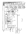
- Fig. 1 is a preferred embodiment of such air suspension system shown.
- the aforementioned compressed air conveying device is shown in the dashed bordered block (1).
- the air discharge device in combination with the air dryer device, hereinafter called air discharge / - drying device (2) shown in the dashed bordered block (4).
- the air suction device is shown in the dashed bordered block (4).
- the aforementioned compressed air reservoir (9) and the bellows (64, 65, 66, 67) are shown.
- the air spring bellows (64, 65, 66, 67) are further associated with displacement sensors (68, 69, 70, 71).
- the displacement sensors (68, 69, 70, 71) are each an electrical signal representative of the level of the vehicle body in the region of that air spring bellows, which they are assigned to an electronic control unit (5) via electrical lines.
- a reversing valve device which serves to control the direction of compressed air flow when conveying the compressed air between the compressed air reservoir (9) and the air bellows (64, 65, 66, 67).
- the compressed air reservoir (9) can be connected as a compressed air source to the air spring bellows (64, 65, 66, 67) alternately in a first switching position.
- the air spring bellows (64, 65, 66, 67) can be connected as a compressed air source to the compressed air reservoir (9). Accordingly, in the first switching position, the function "increase air quantity" with respect to the air spring bellows (64, 65, 66, 67) is adjustable, in the second switching position the function "lower air quantity” is adjustable.
- the Indian Fig. 1 illustrated compressed air reservoir (9) is connected via a designed as an electromagnetically operable 2/2-way valve shut-off valve (8), hereinafter also called storage valve, connected to a terminal (318) of the changeover valve device (3).
- the air spring bellows (64, 65, 66, 67) are each connected via upstream shut-off valves (60, 61, 62, 63), hereinafter also called bellows valves, and via a common compressed air line (72) to a further connection (316) of the changeover valve device (3 ) connected.
- the bellows valves (60, 61, 62, 63) are preferably also designed as electromagnetically operable 2/2-way valves.
- check valves (51, 52) connected on the inlet side are provided.
- the check valve (51) is connected on the outlet side to the air intake device (4) and to a suction port (105) of the compressed-air delivery device (1).
- An outlet port (106) of the compressed air conveying device (1) is connected to an air inlet of the air discharge / drying device (2).
- a check valve (50) is arranged at an outlet of the air discharge / - drying device (2).
- the check valves (50, 52) are connected on the outlet side to a further connection (315) of the changeover valve device (3).
- valve arrangement for controlling the filling of either one, several or all air spring bellows (64, 65, 66, 67) with the compressed air conveying device (1) discharged compressed air is in the subsequent embodiments, the arrangement of the bellows valves (60, 61, 62, 63) considered.
- other types of valves can be used as a valve assembly, for example, proportional valves.
- a pressure sensor (7) is arranged on the outlet side of the check valve (50), which detects the pressure present there and emits a pressure representative of this electrical signal to the electronic control unit (5). If necessary, the pressure sensor (7) can be provided as an option or can be dispensed with in order to achieve more favorable production costs of the air suspension system, as will be explained in more detail below.
- an electric motor (6) is provided which can be switched on via an electrical signal from the electronic control unit (5).
- the electric motor (6) drives a piston machine (12) provided in the compressed air delivery device (1) via a drive shaft (14).
- the electronic control unit (5) is used to control all functions of the air suspension system.
- the control unit (5) via electrical lines with an electrical actuator of the switching valve device (3), the shut-off valves (8, 60, 61, 62, 63), the optional pressure sensor (7), the displacement sensors (68, 69, 70, 71) and the electric motor (6).
- the compressed air conveying device (1) has the functional units explained below.
- a piston machine (12) serves to convey air from the suction port (105) to the outlet port (106) of the compressed air delivery device (1).
- the piston engine (12) can be used as a conventional piston compressor, z. B. as Kippkolbenkompressor be designed.
- the piston engine (12), as mentioned, via a drive shaft (14) can be driven.
- On the suction side of the compressed-air conveying device (1) designed as a check valve suction valve (11) is arranged.
- a likewise designed as a check valve outlet valve (13) is arranged. By the check valves (11, 13), the conveying direction of the compressed-air conveying device (1) is determined.
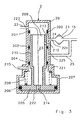
- FIG. 2 An embodiment of such a compressed air conveying device (1) is in the Fig. 2 represented in the form of a reciprocating compressor.
- the abovementioned piston engine (12) has, within its housing, a drive shaft (14) which has a connecting rod (104), a joint (107), a connecting rod (16) and a further joint (18) with a piston (17). mechanically connected. Due to a rotation of the drive shaft (14), the piston (17) performs an upward and downward movement.
- the piston (17) is provided with a circumferential seal (100) which seals a pressure chamber (108) provided above the piston with respect to a suction space (110) provided in the crankcase of the compressor (12).
- the suction valve (11) designed constructively as a lamella is arranged, which is attached to the piston (17) via a screw (19).
- the suction valve (11) serves to seal the pressure chamber (108) with respect to a suction opening (101) penetrating the piston (17) during an upward movement of the piston (17).
- an outlet space (150) is provided above the pressure chamber (108).
- the outlet space (150) is designed constructively designed as a lamella exhaust valve (13) which is fastened by means of a screw (103) on the underside of the outlet space (150).
- the outlet valve (13) seals the outlet chamber (150) against an outlet channel (102) and with respect to the pressure chamber (108) during a downward movement of the piston (17).
- Fig. 1 the air discharge / - drying device (2) in an advantageous embodiment, a compressed air controlled 4/3-way valve (20) and an air dryer (21). Between the 4/3-way valve (20) and the air dryer (21), the volume (15) shown with a storage symbol is shown, the volume of the air discharge / - drying device (2) resulting volumes, in particular of the air dryer Cartridge, represented. In addition, in the volume (15) on the outlet side of the compressed-air conveying device (1) existing volumes are summarized.
- the compressed air delivered by the compressed air conveying device (1) flows in the compressed air in the Fig. 1 illustrated switching position of the valve (20) via a compressed air line (22) at a terminal (223) in the valve (20), at a further terminal (224) from the valve (20) in a compressed air line (24), from there through the Air dryer (21) and from there via the check valve (50) to the switching valve device (3).
- the outlet side of the air dryer (21) is additionally returned via a compressed air line (25) to a further connection (225) of the valve (20), which in the illustrated switching position of Fig. 1 is locked.
- Another connection (215) of the valve (20) serves as a vent connection of the air suspension system; this is connected to the atmosphere.
- connection (223) of the valve (20) connected to the compressed air delivery device (1) is connected via a compressed air line (23) to a pressure-actuated control connection of the valve (20).
- the valve (20) of the in the Fig. 1 shown switching position can be switched to a second and a third switching position.
- the in the first switching position still provided with a relatively large passage cross-section connecting channel between the terminals (223, 224) of the valve (20) is switched in the second switching position in a throttle position with significantly reduced flow area.
- the compressed air line (25) is still shut off in the second switching position.
- the third switching position is finally taken.
- valve (20) in this context also serves as an overpressure safety valve, ie as a safeguard against undesirably high pressure values in the air suspension system, as will be explained below.
- the air dryer device is arranged in an advantageous manner such that they both in normal operation of the air suspension system and in the so-called regeneration mode, d. H. when dehumidifying the dryer granules, is always flowed through in the same flow direction of the compressed air.
- This has the advantage that the air dryer (21) permanently on the outlet side of the compressed-air conveying device (1), in particular spatially relatively close to the compressed-air conveying device, can be arranged and thereby flows in each mode with preheated by the compressed-air conveying device air can be. Due to the spatially sealed arrangement on the compressed air conveying device, the warmed compressed air with relatively little drop in temperature can reach the air dryer (21). Since warm air can absorb the moisture much better than cold air, can be achieved by this embodiment of the invention, a further significant improvement in the efficiency of the regeneration of the dryer granules.
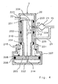
- the valve (20) has a housing (200), which in its lower part of the Fig. 3 shown section has a comparison with its other sections enlarged cross-section.
- the housing (200) can be designed, for example, rotationally symmetrical.
- a valve body (209) is arranged, which is rigidly connected to a piston (205) provided for actuating the valve body (209).
- the piston (205) is guided in the housing portion (207) and sealed by a circumferential seal (206) in the housing portion (207).
- a circumferential seal (206) in the housing portion (207).
- annular seals (201, 202, 204) are disposed in the housing (200) which are held in position by grooves disposed in the housing (200).
- the valve body (209) has a wall (210) which is guided inside the seals (201, 202, 204) and is displaceable due to a movement of the piston (205) relative to the seals (201, 202, 204).
- the housing (200) has openings (223, 224, 225) to which the aforementioned compressed air lines (22, 24, 25) are connected. Furthermore, an opening for the vent connection (215) is provided in the lower region of the housing (200).
- the wall (210) of the valve body (209) has an opening (212) on the side facing the opening (224).
- This opening (212) is dimensioned relatively small in cross section, compared to the other flow areas of the valve (20). In this way, at a compressed air flow through the opening (212), a throttle effect can be achieved, which in the aforementioned second and third switching position of the valve (20) is effective.
- a via the compressed air line (22) fed compressed air stream can in the in the Fig. 3 shown switching position of the valve (20) through the channel (213) in the compressed air line (24) and pass from there through the air dryer (21) to the check valve (50).
- a compressed air flow through the compressed air line (25) is prevented by the seals (202, 204), ie the compressed air line (25) is shut off.
- the compressed air can propagate through an opening (214) penetrating the piston (205) into the space enclosed by the piston (205), the housing bottom (222) and the seal (206) ,
- valve body (209) reaches the seal (201), whereby the in the Fig. 3 shown channel (213) is shut off.
- a compressed air flow from the compressed air line (22) to the compressed air line (24) now takes place through the opening acting as a throttle (212), as indicated by the arrow (216).
- the arrow (23) continues to be a compressed air propagation through the opening (214) in the of the piston (205), the housing bottom (222) and the seal (206) enclosed space.
- the compressed air line (25) is still shut off.
- valve (20) With further increasing pressure in the valve (20) is in the Fig. 5 shown third switching position of the valve (20) taken. In this switching position, the piston (205) bears against the upper side of the housing region (207). A compressed air flow from the compressed air line (22) to the compressed air line (24) continues as in the second switching position throttled through the opening (212), as shown by the arrow (216). The previously closed by the seals (202, 204) and the compressed air line (25) shut-off space is now opposite the seal (204) open so that compressed air from the compressed air line (25) through the opening (215) can flow into the atmosphere, as shown by the arrow (217).
- FIG. 6 an alternative embodiment of the air discharge / drying device (2) is shown.
- a 4/2-way valve is used instead of the previously described 4/3-way valve, ie a simplified executed valve with only two switching positions.
- the valve (20) can be constructed more simply and produced more cheaply.
- the air discharge / drying device (2) can also be provided with an electromagnetically operable valve (219) as a venting valve.
- the bleed valve (219) according to Fig. 7 has an electromagnet (27) as an actuating element instead of the pressure medium actuation.
- the electromagnet (27) can be connected via an electrical line (26) to the control unit (5).
- the air discharge / drying device (2) is provided with a pressure-controlled valve device (220) downstream of the air dryer (21).
- the air dryer (21) is also preceded by a throttle (28).
- the valve device (220) is designed as a 3/2-way valve that is connected in the at the pressure outlet of the air dryer (21) connected to the compressed air line. This results in a simple guidance of the compressed air lines on the outlet side of the air dryer (21).
- a further embodiment of the air discharge / - drying device (2) is shown, which, as in the Fig. 8 a throttle (28) upstream of the air dryer (21) and a pressure-controlled valve device (29) connected downstream of the air dryer (21).
- the valve device (29) is designed as a 2/2-way valve.
- the air discharge / - drying device (2) is particularly inexpensive to produce.
- additional branch point of the compressed air lines on the outlet side of the air dryer can be advantageously integrated directly into the valve device (29) in a practical realization, so that in relation to the embodiment according to Fig. 8 no increased effort in terms of leadership of the compressed air lines results.
- the throttle (28) is designed such that sufficient for the desired requirements compressed air flow through the throttle (28) is possible.
- the passage cross section of the valve device (29, 220) should be significantly larger than the passage cross section of the throttle (28), e.g. in the ratio 4: 1.
- FIG. 6 8 and 9 illustrated embodiments of the air discharge - / - drying device (2) analogous to the embodiment according to Fig. 7 also be equipped as needed with an electromagnetically actuated vent valve instead of the illustrated pressure-actuated valves (20, 220, 29).
- Fig. 1 is proposed as reversing valve device (3) precontrolled by compressed air, electromagnetically actuated directional control valve arrangement consisting of a pilot valve (31) and a changeover valve (30).
- the pilot valve (31) is designed as an electromagnetically operated 3/2-way valve, which is actuated by the control unit (5) via an electrical line.
- the switching valve (30) is designed as a pneumatically actuated 4/2-way valve which is connected via compressed air connections (315, 316, 317, 318) with the other parts of the air suspension system.
- the compressed air actuatable control input of the changeover valve (30) is connectable via the pilot valve (31) optionally with the of the compressed air conveying means (1) via the air discharge / - drying device (2) and the check valve (50) pressure or with the atmosphere.
- the control volume of this valve is to be kept low.
- An embodiment of such a designed switching valve with low control volume is in the Fig. 13 and 14 shown.
- it is advantageous to minimize the switching frequency by means of suitable control algorithms in the control unit (5) in order to minimize the consumption of air.
- valve assembly (3) with a pilot valve has the advantage that the actuating forces, which must apply the solenoid, turn out lower.
- the electromagnet can be designed smaller and cheaper.
- the removal of the pilot pressure from the compressed air output branch of the compressed air conveying device (1) has the advantage that the changeover valve device (3) is functional in any operating condition of the air suspension system, z. B. even at initial startup at still empty compressed air storage (9).
- FIG. 10 an alternative embodiment of the reversing valve device (3) with an electric motor operated, designed as a slide valve switching valve (30) and one of the control unit (5) actuatable for actuation electric motor (32) is shown.
- a further alternative embodiment of the switching valve device (3) is in the Fig. 11 shown.
- switching valve device (3) can with respect to their compressed air connection sides (35, 36) at will in accordance with the air suspension system Fig. 1 to get integrated.
- the connection side (35) with the compressed air conveying device and the connection side (36) are connected to the compressed air reservoir or the air spring bellows.
- the connection side (36) with the compressed air conveying device and then the connection side (35) with the compressed air reservoir and the air spring bellows are connected.
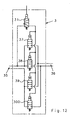
- FIG. 12 Another embodiment of the switching valve device (3) is in the Fig. 12 specified.
- four pneumatically operable 2/2-way valves (37, 38, 39, 300) are used for switching, which can be actuated by the already explained pilot valve (31).
- the connection sides (35, 36) of the switching valve device (3) can also, as shown in the Fig. 11 explained, optionally in the air suspension system according to Fig. 1 be connected.
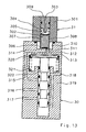
- FIG. 13 Based on Fig. 13 and 14 an advantageous structural design of the in the Fig. 1 illustrated switching valve device (3) are explained.
- the changeover valve device (3) is shown in the unactuated state, in the Fig. 14 in the actuated state.
- the switching valve device (3) consists, as explained, of the pilot valve (31) and the switching valve (30).
- the pilot valve (31) has an electromagnet arrangement (301, 302) which is designed as an electrical coil (301) and an armature (302) arranged inside the coil (301) and movable in the longitudinal direction of the coil (301).
- the armature (302) also serves as a valve closing body.
- the armature is provided at its one end face with a seal consisting of an elastomer (305) and at its opposite end face with a further likewise consisting of an elastomer seal (306).
- the armature (302) has longitudinally extending grooves (307, 308) serving as air ducts.
- the armature (302) rests on a spring (304) disposed within the coil (301).
- the spring (304) in turn is supported on a valve closure piece (309), which the pilot valve (31) at its top closes.
- the valve closure piece (309) is provided with a bore extending along its longitudinal axis, which serves as a pressure outlet channel (303) for venting into the atmosphere from the pilot valve (31) in the switching valve (30) einêtbaren compressed air.
- the pilot valve (31) is connected to the switching valve (30) to a rigid unit.
- the armature (302) is urged by the force of the spring (304) onto a valve seat (311) provided in the change-over valve (30).
- the seal (306) closes the valve seat (311).
- the seal (305) is not in this state on the valve closure piece (309), ie, the pressure outlet channel (303) is opened.
- the change-over valve (30) consists of a valve housing (319) which has various compressed-air connections (314, 316, 317, 318) and ventilation ducts (314, 312).
- the compressed air connection (315) is used for connection to the outlet side of the compressed-air conveying device (1), ie on the basis of the representation of Fig. 1 for connection to the outlet sides of the check valves (50, 52).
- the compressed air connection (317) is used for connection to the suction side of the compressed-air conveying device (1), ie according to Fig. 1 for connection to the inlet sides of the check valves (51, 52).
- the compressed air connection (318) is used to connect the compressed air reservoir (9) via the storage valve (8).
- the compressed air connection (316) is used to connect the air spring bellows (64, 65, 66, 67) via the bellows valves (60, 61, 62, 63).
- compressed air to be used for precontrol can flow to the pilot valve (31) or to the armature (302).
- the armature (302) against the force of the spring (304) in the in the Fig. 14 shown position moves.
- the valve seat (311) is released, so that compressed air via a chamber (310) and via the compressed air passage (312) in a pilot chamber (313) can flow.
- the pilot chamber (313) is bounded by a longitudinally movable piston (320), which is acted upon by the in the pilot chamber (313) located compressed air.
- the piston (320) is supported by a spring (321) on a counter-stop in the valve housing (319).
- the air suction device (4) As another functional unit is in the Fig. 1 the air suction device (4) is provided. This has an atmosphere connected to the air intake port (42), a filter (41) for filtering out impurities in the ambient air and a check valve (40).
- This type of embodiment of the air intake device (4) has the advantage that with appropriate air requirement on the suction side of the compressed-air conveying device (1), z. B. at too low pressure in the compressed air reservoir (9) or shut-off valves (8, 60, 61, 62, 63) in the case of regeneration of the dryer granules, air is sucked in a sufficient manner automatically from the atmosphere, since the check valve (40) requires no special control.
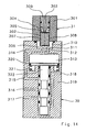
- An alternative embodiment of the air intake device (4) is in the Fig. 17 shown.
- an electromagnetically operable 2/2-way valve (43) is used as an intake valve, which via an electrical line (44) of the control unit (5) can be actuated.
- An actuation by the control unit (5) takes place whenever there is an intake requirement from the atmosphere, for. B. in regeneration mode or to adjust the effective flow rate of the compressed-air conveying device (1).
- the pressure sensor (7) determined output pressure of the compressed-air conveying device (1) are also closed to a suction requirement.
- a further pressure sensor could be provided on the suction side of the compressed air conveying device, which emits a pressure signal to the control unit (5).
- an overflow valve (74) which acts as a pressure relief valve and with the terminals (316, 318) of the switching valve device (3) is connected.
- the overflow valve (74) causes a pressure in the compressed air line (72) exceeding a predetermined pressure to flow through the compressed air to the port (318) and consequently a return flow of the compressed air via the port (317), the check valve (51) to the suction port (105) of the compressed air conveying device (1).
- the present in the compressed air line (72) pressure is reduced, but this is not considered to control the effective flow rate according to claim 1.
- the response pressure of the spill valve (74) is preferably set so that an overflow and thus a pressure reduction on the outlet side of the compressed-air conveying device (1) takes place when less than three of the bellows valves (60, 61, 62, 63) connected in the open position are.
- FIG. 16 is arranged as a bypass valve instead of the above-mentioned spill valve (74), an electromagnetically actuated 2/2-way valve (73) in an analogous manner as the spill valve (74).
- the 2/2-way valve (73) is connected via an electrical line to the control unit (5) and actuated by an electrical signal from this.
- the effective delivery rate of the compressed air conveying device (1) is reduced by returning the conveyed air to the suction port (105) of the compressed air conveying device (1).
- bypass valve (73) is not limited to the previously described embodiments. Rather, the bypass valve (73) between any points of the suction side of the compressed-air conveying device (1) on the one hand and the outlet side of the compressed-air conveying device (1) on the other hand can be arranged.
- the air suspension system described above with respect to its structure can be operated in a number of operating modes, which will be explained below.
- the air suspension system is in accordance with Fig. 1 the compressed air reservoir (9) and the Heilfederbälge (64, 65, 66, 67) initially at a pressure level corresponding to the atmospheric pressure.
- a sufficient amount of compressed air for a proper function of the air suspension system thus thus does not exist in this state.
- a connection between the outlet port (106) of the compressed-air conveying device (1) and the air spring bellows (64, 65, 66, 67) is connected by means of the changeover valve device (3).
- the compressed air reservoir (9) with the suction side of the compressed air conveying device (1) is connected.
- the storage valve (8) and the bellows valves (60, 61, 62, 63) are switched to the open position. Then, the electric motor (6) is turned on, so that the compressed air conveying means (1) starts to supply compressed air.
- the resulting level position is over the displacement sensors (68, 69, 70, 71) monitored by the control unit (5).
- the control unit (5) switches the air bellows upstream bellows valve (60, 61, 62, 63) in the shut-off position.
- the control unit (5) shuts off the electric motor (6) and the storage valve (8) switches to the shut-off position. This completes the filling process of the air spring bellows (64, 65, 66, 67).
- the air spring bellows (64, 65, 66, 67) can be useful when starting up the air suspension system and a filling of the initially at atmospheric pressure compressed air reservoir (9).
- a connection between the outlet port (106) of the compressed air conveying device (1) and the compressed air reservoir (9) is switched by means of the changeover valve device (3).
- the storage valve (8) is switched to the open position, the bellows valves (60, 61, 62, 63) remain in the shut-off position.
- the electric motor (6) is turned on, so that the compressed air conveying means (1) starts to supply compressed air.
- the compressed air conveying device (1) then sucks air from the atmosphere through the air intake device (4).
- the sucked air is discharged to the outlet side of the compressed air conveying device (1) and flows through the air discharge / - drying device (2), the check valve (50), the changeover valve device (3) and the storage valve (8) in the compressed air reservoir (9 ).
- This filling process of the compressed air reservoir (9) can be timed, e.g. the electric motor (6) is turned on for a predetermined refill period. If the pressure sensor (7) is provided, the resulting pressure level is monitored by the control unit (5) via the pressure sensor (7). After expiration of the predetermined refill period or upon reaching a desired pressure value, the control unit (5) switches off the electric motor (6) again and also switches the storage valve (8) into the shut-off position. This completes the filling process of the compressed air reservoir (9).
- the previously explained refilling process or the operating mode "underpressure compensation” is set automatically by the control unit (5) even during later operation of the pneumatic suspension system if, based on the signals from the sensors (7, 68, 69, 70, 71), a too small amount of air in the Air suspension system is suspected.
- the control unit (5) by means of the switching valve device (3) connects the compressed air reservoir (9) with the suction side of the compressed-air conveying device (1).
- the control unit (5) by means of the switching valve device (3) connects the compressed air reservoir (9) with the suction side of the compressed-air conveying device (1).
- the control unit (5) by means of the switching valve device (3) connects the compressed air reservoir (9) with the suction side of the compressed-air conveying device (1).
- the control unit (5) by means of the switching valve device (3) connects the compressed air reservoir (9) with the suction side of the compressed-air conveying device (1).
- the air discharge / - drying device (2) causes the incoming overpressure switching the valve (20) in its third switching position, so that the compressed air further through the valve (20), the compressed air line (24), the air dryer (21), the compressed air line (25) and in turn through the valve (20) through the vent port (215) can flow into the atmosphere.
- the state "overpressure compensation” can be maintained, for example, until the overpressure has reduced so much that the valve (20) automatically returns to its second switching position.
- a regulation and limitation of the overpressure by appropriate coordination between the compressed air actuation of the valve (20) and the return spring (208), in other words, by appropriate choice of the effective area of the piston (205) and the force of the spring (208 ).
- the adjustment and maintenance of a suitable pressure range in the air suspension system takes place even without the use of the pressure sensor (7) quasi automatically, as on the one hand automatically opens the check valve (40) and thus allows an air intake from the atmosphere, on the other hand at a corresponding overpressure automatically the valve (20) opens and allows outflow of excess air into the atmosphere.
- the illustrated air suspension system is thus functional even without the pressure sensor (7).
- z. B. be omitted for cost reasons on this pressure sensor.
- a pressure sensor (7) is provided, there is a further advantage in that even with a defect or failure of the pressure sensor (7), the air suspension system can continue to operate safely.
- An avoidance of unacceptable pressure in the compressed air reservoir (9) can, for. B. in an air suspension system without pressure sensor (7) by connecting the compressed air reservoir (9) with the overpressure safety valve (20) at regular intervals, eg. B. every 30 minutes, be ensured.
- control algorithms can be realized, which can be provided in the control unit (5) as a control program, and can be achieved by the other advantages in the control of the air suspension system.
- the control unit (5) in an advantageous embodiment of the invention performs a regular monitoring of the pressure in the compressed air reservoir (9).
- the control unit (5) connects the compressed air reservoir (9) by actuation of the accumulator valve (8) and the reversing valve device (3) with the pressure sensor (7).
- About the check valves (50, 52) is prevented that the compressed air from the compressed air reservoir (9) undesirably spreads to other branches of the air suspension system. If the control unit (5) determines in such a regular check that the pressure in the compressed air reservoir (9) exceeds a desired limit value, the control unit (5) sets the operating mode "overpressure compensation".
- control unit (5) interrupts the above-described overpressure venting via the valve (20) by switching over the changeover valve device (3) at predetermined time intervals such that in turn a connection is established between the pressure sensor (7) and the compressed air reservoir (9) so that the remaining air pressure in the compressed air reservoir can be measured. If a pressure value is determined which is above a limit value stored in the control unit (5), then the control unit (5) switches over the changeover valve device (3) again so that a further overpressure reduction can take place via the valve (20). Otherwise, the control unit (5) ends the operating state "overpressure compensation" and in turn sets the operating mode "neutral state".
- control unit (5) checks the pressure values present in the air spring bellows (64, 65, 66, 67) at certain intervals by connecting one of the air spring bellows (64, 65, 66, 67) to the pressure sensor (7) suitable control of the switching valve device (3) and the shut-off valves (8, 60, 61, 62, 63).
- the determined pressure values of the air spring bellows (64, 65, 66, 67) and the compressed air reservoir (9) are stored in the control unit (5).
- the control unit (5) may be programmed in an advantageous embodiment such that it limits said pressure difference to a predetermined value.
- the control unit (5) switches the air suspension system into the already described operating mode "overpressure compensation", wherein additionally Turning on the electric motor (6) the compressed air conveying device (1) by the control unit (5) is set for a predetermined time in operation. As a result, a certain amount of air is pumped via the valve (20) into the atmosphere. After the predetermined time has elapsed, the control unit (5) switches off the compressed-air delivery device (1) again and again checks the pressure present in the compressed-air accumulator (9).
- the control device (5) switches the air suspension system into the "reduced pressure compensation" operating mode already explained. As a result, air is sucked from the atmosphere via the air intake device (4) and pumped into the compressed air reservoir (9). When a desired pressure value is reached, the control unit (5) switches the air suspension system back to the "Neutral" operating mode.
- the control unit (5) checks based on the signals of the displacement sensors (68, 69, 70, 71), whether the level position of the vehicle body relative to the vehicle wheels or the roadway corresponds to a desired target value.
- This setpoint can be z. B. depending on the driving situation automatically from the control unit (5) from a number of predetermined Setpoints or setpoint functions are selected. It can also be a setpoint by manual intervention z. B. be provided by the driver.
- the control unit (5) then controls the air suspension system in the operating mode "Increase".
- the compressed air reservoir (9) is connected by switching the accumulator valve (8) in the open position with the changeover valve device (3).
- the switching valve device (3) is switched such that the compressed air reservoir (9) is connected to the suction side of the compressed air conveying device (1).
- the outlet side of the compressed-air conveying device (1) with the bellows valves (60, 61, 62, 63) is connected.
- the control unit (5) further switches the bellows valve (60) in the open position.
- the compressed air flows directly through the non-return valve (52) even when the compressed air conveying device (1) is stationary, and additionally into the compressed air conveying device (1) Air spring bellows (64), ie
- the check valve (52) By means of the check valve (52), the compressed air conveying device (1) can be bridged in the manner of a bypass.
- the direct connection via the check valve (52) a lesser and thus more favorable flow resistance is achieved.
- the control unit (5) monitors the filling of the air spring bellows (64) on the basis of the pressure signal output by the pressure sensor (7) and the travel signal output by the displacement sensor (68). As soon as the desired setpoint of the level position on the air spring bellows (64) is reached, the control unit (5) switches the storage valve (8) and the bellows valve (60) into the shut-off position.
- the control unit (5) switches on the electric motor (6) to assist the air delivery, whereby the compressed air delivery device (1 ) is put into operation.
- the compressed air delivery device (1 ) is put into operation.
- the pressure in the compressed air reservoir (9) is less than or equal to the pressure in the air spring bellows (64) to be filled, or when the filling of the air spring bellows is to be accelerated.
- the check valve (50) for this purpose as close as possible to the Umschaltventil raised (3) arranged to minimize compensation operations on the compressed air lines.
- the compressed air conveying device (1) Should it happen when conveying the air from the compressed air reservoir (9) by the compressed air conveying device (1) that the amount of compressed air in the compressed air reservoir (9) is not sufficient for filling the exemplified air spring bellows (64), the air pressure would the suction side of the compressed air conveying means (1) fall below the atmospheric pressure, whereby the check valve (40) of the air suction device (4) opens automatically. This allows the compressed air delivery device (1) automatically and without further intervention by the control unit (5) suck the necessary air from the atmosphere and thus provide the required amount of air in the air bag (64).
- the air spring bellows (64) should be vented.
- the control unit (5) controls the air suspension system in the operating mode "lowering".
- the storage valve (8) and the bellows valve (60) are switched to the open position.
- the switching valve device (3) is switched such that the air spring bellows (64) with the suction side of the compressed-air conveying device (1) and the compressed air reservoir (9) with the outlet side of the compressed-air conveying device (1) is connected.
- the control unit (5) monitors the venting of the air spring bellows (64) via the sensors (7, 68). When the desired level position is reached in accordance with the setpoint at the air bag (64), the control unit (5) ends the operating mode "lowering" by the storage valve (8) and the bellows valve (60) are switched to the shut-off position.
- the control unit (5) switches on the electric motor (6) to assist the air delivery, whereby the compressed air delivery device (1 ) is put into operation. This is particularly necessary if the pressure in the air spring bellows (64) to be emptied is less than or at most equal to the pressure in the compressed air reservoir (9), or when the evacuation of the air spring bellows is to be accelerated. An intake of air from the atmosphere via the air intake device (4) is not considered in this mode of operation.
- the compressed air delivery device (1) therefore sucks in air from the air spring bellows (64) via the bellows valve (60), the changeover valve device (3) and the check valve (51) and conveys them via the air discharge / drying device (2) Check valve (50), the changeover valve device (3) and the storage valve (8) in the compressed air reservoir (9).
- the valve (20) serving for overpressure protection is activated automatically and switches to its third switching position, so that the compressed air delivery device (1) conveyed compressed air is vented into the atmosphere.
- the control unit (5) can also be checked on reaching a predetermined pressure value stored in the control unit (5) in the compressed air reservoir (9) which is based on the signal of the pressure sensor (7). Prevent further conveying compressed air into the compressed air reservoir (9) by the control unit (5) switches the storage valve (8) in the shut-off position. The henceforth of the compressed air conveying means (1) conveyed compressed air is then vented as a result of a rapidly increasing pressure at the opposite the compressed air reservoir (9) shut off outlet side of the compressed-air conveying device (1) via the valve (20) into the atmosphere.
- the check valve (51) for this purpose as close as possible to the changeover valve device (3) arranged to minimize compensation operations on the compressed air lines.
- a typical size for the volume (10) in passenger air suspension systems is about 0.5 liters, for the volume (15) about 0.4 liters.
- the check valves (50, 51) can on a structurally complex volume minimization in the compressed air conveying device (1), often structurally integrated into the compressed air conveying device (1) electric motor (6) and the air discharge - / - drying device (2 ) are waived. Instead, a targeted optimization of the design in terms of cost can be performed.
- the operating mode "regeneration” is used for regeneration, d. H. for dehumidifying, in the air dryer (21) provided dryer granules.
- the control unit (5) switches the storage valve (8) and the bellows valves (60, 61, 62, 63) in the shut-off position and sets by switching on the electric motor (6), the compressed-air conveying device (1) into operation.
- the compressed air conveying device (1) then sucks in air from the atmosphere via the air suction device (4) and delivers this compressed air on the outlet side, wherein the compressed air is heated to the ambient temperature.
- the valve (20) first switches from the first switching position into the second switching position and finally into the third switching position.
- the compressed air from the compressed air line (22) through the valve (20) throttled flows into the compressed air line (24), d. H. the compressed air expands to a lower pressure level than the pressure level present in the compressed air line (22).
- the Heilabgabe - / - drying device (2) is preferably arranged spatially relatively close to the compressed air conveying device (1), so that the heated compressed air arrives in the air dryer (21) without significant reduction in temperature.
- the thus relaxed and also heated air has a relatively high moisture absorption potential, so that the compressed air flowing from the air dryer (21) in the compressed air line (25) has a relatively high moisture content.
- This air is then vented through the valve (20) into the environment. As a result, a very efficient and rapid drying of the dryer granules is achieved.
- the regeneration of the dryer granules is also always carried out when the already explained operating mode "overpressure compensation" is executed, d. H. at degradation of z. B. in the compressed air reservoir (9) stored excess compressed air via the valve (20). In this case, it is not necessary to draw in air from the atmosphere.
- the operating mode "regeneration" of the control unit (5) is always carried out automatically following one of the other operating modes, if in this case the compressed air conveying device (1) has been put into operation.
- the control unit (5) performs the operating mode "regeneration" in the sense of a caster, ie at the end of a previous operating mode, eg. B. "increase", the accumulator valve (8) and the bellows valves (60, 61, 62, 63) are switched to the shut-off, the electric motor (6) but not immediately switched off, but left turned on for a follow-up.
- the compressed air conveying device (1) continues to run and builds on the outlet side to an overpressure.
- the pressurized air then escapes via the valve (20) and the air dryer (21), so that the described regeneration of the dryer granules is performed.
- the controller switches (5) the electric motor (6), whereby the air suspension system from the operating mode "regeneration” in the operating mode "normal state” passes. This ensures that the dryer granules at all times has sufficient moisture absorption capacity.
- the air dryer (21) is always traversed in all operating modes of the air suspension system in the same flow direction of the compressed air.
- This makes it possible to arrange the check valve (50) in the compressed air line between the air discharge - / - drying device (2) and the Umschaltventil sensible (3), such that the check valve (50) is arranged relatively close to the Umschaltventil sensible (3), ie downstream of the air discharge / drying device (2).
- This has the advantage that in the operating mode "increase” an undesirable lowering of the level position due to a pressure equalization between the volume (15) and the bellows can be particularly effectively avoided.
- an air drying concept in which the air dryer (21) in the regeneration mode in the opposite flow direction of the compressed air is flowed when conveying compressed air by the compressed air conveying device (1), as known from the aforementioned prior art, then would have the check valve (50) in the air suspension system according to Fig. 1 between the compressed air conveying device (1) and the air discharge / - drying device (2) are arranged.
- the check valve (50) could not prevent pressure equalization operations between the volumes present in the air discharge / drying device (2) and the air bellows. The consequence would be that in the operating mode "increase" an undesirable lowering of the level position due to the pressure compensation can occur.
- a further advantage which results from the air discharge / drying device (2) through which the compressed air flows in the same direction of flow and the check valve (50) arranged as a result in the compressed air line between the air discharge / drying device (2) and the changeover valve device (3) ), is that when reducing an overpressure in the operating mode "overpressure compensation", the air can not escape without flowing through the air dryer (21) into the atmosphere, since the check valve (50) prevents this. As a result, all of the compressed air vented into the atmosphere benefits the regeneration of the dryer granulate.
- controller (5) e.g. as a program part in a control program executed in the control unit (5), be provided to switch the air suspension system in the operating mode "regeneration" when a high moisture density is present in the air suspension system.
- an additional humidity sensor for determining the air humidity in the air suspension system can be provided, which emits a signal representing the air humidity to the control unit (5).
- the air suspension system can still be operated in the operating mode "starting assistance".
- This operating mode is always required when the drive power that can be applied by the electric motor (6) does not cause the compressor (12) to start up. This can, for example, at a relatively high back pressure on the outlet side, d. H. in the outlet space (150) of the compressor (12), in particular when the piston (17) is in a position approximately midway between the two dead centers.
- the storage valve (8) is first opened and the changeover valve device (3) is switched over for a short time before starting the electric motor (6), d. H. operated in each of the two switching positions.
- the electric motor (6) is started.
- control unit (5) recognizes a start-up aid requirement by periodically monitoring the pressure values determined by the pressure sensor (7), or by evaluating the stored pressure values of the compressed air reservoir (9) and the air spring bellows or by monitoring of the electric motor ( 6) absorbed current.
- the control unit (5) connects with recognized start-up assistance by suitable control of the Umschaltventil worn (3) and the shut-off valves (8, 60, 61, 62, 63) either the compressed air reservoir (9) or a bellows with relatively high air pressure with the suction side of Compressed air conveying device (1).
- the piston (17) of the compressor (12) is pressurized from its underside, so that for a start of the compressor (12) required by the electric motor (6) to be fed driving power is reduced. Once the compressor (12) has started, can be switched back to the actual desired operating mode of the air suspension system.
- a stepless or fine adjustment of the operating voltage of the electric motor (6) can be provided in the control unit (5).
- the setting options "normal operating speed” and “reduced operating speed” are conceivable.
- the reduced operating speed step may also be accomplished by intermittent operation of the electric motor (6) or compressed air conveying device (1), i. by regular switching on and off, be realized.
- the operating mode "reduced delivery rate” is present when the electric motor (6) is operated in the "reduced operating speed” mode.
- the operating mode "reduced flow rate” is present when the vent valve (219) is actuated by the control unit (5) with an electrical signal and as a result venting of compressed air via the vent port (215) into the atmosphere.
- the embodiment III. is when using the air suspension system according to Fig. 1 the operating mode "reduced flow rate" before, when the storage valve (8) is switched by the control unit (5) in the closed position.
- the "reduced flow rate" mode of operation is set by switching the suction valve (43) to the open position by electrical signal from the control unit (5) via the electric line (44) and, as a result, also drawing in air from the atmosphere.
- a pressure sensor (7), a speed sensor and / or a current sensor are provided.
- a pressure sensor (7), a speed sensor and / or a current sensor are provided.
Claims (5)
- Procédé de fonctionnement d'une suspension pneumatique pour un véhicule, en particulier une suspension pneumatique réalisée sous la forme d'un système partiellement fermé, équipée d'au moins un dispositif de refoulement d'air comprimé (1), d'une pluralité de soufflets pneumatiques (64, 65, 66, 67) ainsi qu'un dispositif de soupape (60, 61, 62, 63) pour la commande du remplissage d'un, de plusieurs ou de tous les soufflets pneumatiques (64, 65, 66, 67) au choix avec l'air comprimé délivré par le dispositif de refoulement d'air comprimé (1), caractérisé en ce que la capacité de refoulement efficace du dispositif de refoulement d'air comprimé (1) est automatiquement commandée par un appareil de commande électronique (5) selon le type de remplissage des soufflets pneumatiques (64, 65, 66, 67) choisi grâce au dispositif de soupape (60, 61, 62, 63), et en ce que, lors de la commande automatique de la capacité de refoulement efficace, un mode de fonctionnement "capacité de refoulement normale" et un mode de fonctionnement "capacité de refoulement réduite", dans lequel la capacité de refoulement efficace est plus faible que dans le mode de fonctionnement "capacité de refoulement normale", peut être réglé avec les caractéristiques suivantes :a) la suspension pneumatique comporte quatre soufflets pneumatiques (64, 65, 66, 67),b) lors du refoulement de l'air comprimé par le dispositif de refoulement d'air comprimé (1) dans trois ou quatre soufflets pneumatiques (64, 65, 66, 67), le mode de fonctionnement "capacité de refoulement normale" est utilisé,c) sinon, lors du refoulement de l'air comprimé par le dispositif de refoulement d'air comprimé (1), le mode de fonctionnement "capacité de refoulement réduite" est utilisé.
- Procédé selon la revendication 1, caractérisé en ce que l'adaptation de la capacité de refoulement efficace est réalisée par une commande de vitesse ou de nombre de tours du dispositif de refoulement d'air comprimé (1).
- Procédé selon au moins une des revendications précédentes, caractérisé en ce que la suspension pneumatique présente au moins un raccord de purge (215), qui est utilisé pour purger l'air comprimé dans l'atmosphère, et en ce que l'adaptation de la capacité de refoulement efficace s'effectue par purge de l'air comprimé par l'intermédiaire du raccord de purge (215) dans l'atmosphère, et en ce qu'une soupape de purge (219) pouvant être commandée par un signal électrique est prévue pour purger l'air comprimé dans l'atmosphère.
- Procédé selon au moins une des revendications précédentes, caractérisé en ce que la suspension pneumatique présente au moins un dispositif d'aspiration d'air (4), qui est utilisé pour aspirer l'air de l'atmosphère, et en ce que l'adaptation de la capacité de refoulement efficace s'effectue par aspiration de l'air depuis l'atmosphère par l'intermédiaire du dispositif d'aspiration d'air (4), et en ce qu'une soupape d'aspiration (43) pouvant être commandée par un signal électrique est prévue pour aspirer l'air depuis l'atmosphère.
- Procédé selon au moins une des revendications précédentes, caractérisé en ce que, en vue de l'adaptation de la capacité de refoulement efficace entre le côté d'aspiration et le côté d'évacuation du dispositif de refoulement d'air comprimé (1), est disposée une soupape de dérivation (73), grâce à laquelle un flux d'air comprimé de dérivation peut circuler par l'intermédiaire de la dérivation du dispositif de soupape (60, 61, 62, 63) ou des parties de celui-ci du côté d'évacuation vers le côté d'aspiration du dispositif de refoulement d'air comprimé, et
en ce qu'une électrovanne (73) pouvant être actionnée par un signal de commande électrique est utilisée comme soupape de dérivation (73, 74).
Applications Claiming Priority (2)
| Application Number | Priority Date | Filing Date | Title |
|---|---|---|---|
| DE10303399 | 2003-01-29 | ||
| DE10303399A DE10303399B4 (de) | 2003-01-29 | 2003-01-29 | Verfahren zum Betrieb einer Luftfederungsanlage für ein Fahrzeug |
Publications (3)
| Publication Number | Publication Date |
|---|---|
| EP1442903A1 EP1442903A1 (fr) | 2004-08-04 |
| EP1442903B1 EP1442903B1 (fr) | 2006-10-11 |
| EP1442903B2 true EP1442903B2 (fr) | 2011-05-18 |
Family
ID=32603015
Family Applications (1)
| Application Number | Title | Priority Date | Filing Date |
|---|---|---|---|
| EP04000095A Expired - Fee Related EP1442903B2 (fr) | 2003-01-29 | 2004-01-07 | Procédé pour faire fonctionner une suspension pneumatique pour véhicule |
Country Status (3)
| Country | Link |
|---|---|
| US (1) | US7552932B2 (fr) |
| EP (1) | EP1442903B2 (fr) |
| DE (2) | DE10303399B4 (fr) |
Cited By (1)
| Publication number | Priority date | Publication date | Assignee | Title |
|---|---|---|---|---|
| WO2021008872A1 (fr) | 2019-07-17 | 2021-01-21 | Wabco Europe Bvba | Système correcteur d'assiette pour des véhicules équipé d'une suspension pneumatique |
Families Citing this family (40)
| Publication number | Priority date | Publication date | Assignee | Title |
|---|---|---|---|---|
| DE10240359A1 (de) * | 2002-09-02 | 2004-03-11 | Wabco Gmbh & Co. Ohg | Luftfederungsanlage für ein Fahrzeug |
| DE10240357B4 (de) * | 2002-09-02 | 2016-10-06 | Wabco Gmbh | Luftfederungsanlage für ein Fahrzeug |
| DE10333610B4 (de) * | 2003-07-24 | 2005-09-15 | Haldex Brake Products Gmbh | Druckluftaufbereitungseinrichtung für Kraftfahrzeug-Druckluftanlagen |
| DE102005030467B4 (de) * | 2005-06-28 | 2007-04-05 | Knorr-Bremse Systeme für Nutzfahrzeuge GmbH | Luftfederungseinrichtung für Fahrzeuge mit Drossel |
| DE102005030726A1 (de) * | 2005-07-01 | 2007-01-04 | Continental Aktiengesellschaft | Luftfederungsanlage für ein Kraftfahrzeug |
| US7841608B2 (en) * | 2007-07-31 | 2010-11-30 | Hendrickson Usa, L.L.C. | Pneumatic proportioning system for vehicle air springs |
| JP5291317B2 (ja) * | 2007-09-28 | 2013-09-18 | 日立オートモティブシステムズ株式会社 | スクロール式流体機械及びそれを用いたエアサスペンション装置 |
| KR100881081B1 (ko) * | 2007-10-22 | 2009-01-30 | 현대모비스 주식회사 | 에어 서스펜션 시스템 |
| DE102008005429A1 (de) * | 2008-01-22 | 2009-07-23 | Knorr-Bremse Systeme für Nutzfahrzeuge GmbH | Kompressor und Verfahren zur Steuerung eines Kompressors zur Druckluftversorgung eines Nutzfahrzeugs |
| EP2112009B1 (fr) * | 2008-04-24 | 2011-06-22 | Continental Teves AG & Co. oHG | Procédé de vérification d'une soupape d'environnement dans une installation de réglage de niveau fermée d'un véhicule |
| DE102008034240B4 (de) | 2008-07-23 | 2014-12-18 | Wabco Gmbh | Niveauregelanlage für Fahrzeuge und Verfahren zum Betreiben einer Niveauregelanlage |
| DE102009003395A1 (de) * | 2009-01-28 | 2010-07-29 | Continental Aktiengesellschaft | Niveauregelanlage für ein Fahrzeug |
| DE102010012413A1 (de) * | 2010-03-23 | 2011-09-29 | Miro Gudzulic | Ventil |
| DE102010017654A1 (de) * | 2010-06-30 | 2012-01-05 | Continental Teves Ag & Co. Ohg | Höhenabhängige Kompressorsteuerung |
| DE102010054704A1 (de) * | 2010-12-16 | 2012-06-21 | Wabco Gmbh | Druckluftversorgungsanlage und pneumatisches System |
| DE102011084921A1 (de) | 2011-10-20 | 2013-04-25 | Continental Teves Ag & Co. Ohg | Kompressorschaltung für eine pneumatische Regelvorrichtung eines Fahrzeugs |
| DE102011121756A1 (de) * | 2011-12-21 | 2013-06-27 | Wabco Gmbh | Luftfederungsanlage eines Kraftfahrzeugs und Verfahren zu deren Steuerung |
| DE102011121755A1 (de) * | 2011-12-21 | 2013-06-27 | Wabco Gmbh | Luftfederungsanlage eines Kraftfahrzeugs und Verfahren zu deren Steuerung |
| DE102012001736A1 (de) * | 2012-01-31 | 2013-08-01 | Wabco Gmbh | Druckluftversorgungsanlage, pneumatisches System und Verfahren zum Betreiben einer Druckluftversorgungsanlage bzw. eines pneumatischen Systems |
| DE102012001734B4 (de) * | 2012-01-31 | 2020-11-12 | Wabco Gmbh | Druckluftversorgungsanlage, pneumatisches System und Verfahren zum Betreiben einer Druckluftversorgungsanlage bzw. eines pneumatischen Systems |
| DE102012006382A1 (de) * | 2012-03-30 | 2013-10-02 | Wabco Gmbh | Druckmittelversorgungsanlage, pneumatisches System und Verfahren zum Betreiben einer Druckmittelversorgungsanlage |
| DE102013003513A1 (de) * | 2013-03-04 | 2014-09-04 | Wabco Gmbh | Verdichteranordnung zum Betreiben einer Druckluftversorgungsanlage, Druckluftversorgungsanlage und Druckluftversorgungssystem sowie Fahrzeug mit einer solchen Druckluftversorgungsanlage |
| PL2908024T3 (pl) * | 2014-02-17 | 2024-02-26 | Special Springs S.R.L. | Urządzenie do regulowanego zwiększania ciśnienia w siłownikach w postaci cylindrów gazowych |
| DE102014207509A1 (de) * | 2014-04-17 | 2015-10-22 | Continental Teves Ag & Co. Ohg | Integrierte Luftversorgungseinheit |
| JP2017159760A (ja) * | 2016-03-09 | 2017-09-14 | トヨタ自動車株式会社 | 車高制御システム |
| JP6378228B2 (ja) * | 2016-03-14 | 2018-08-22 | トヨタ自動車株式会社 | 車高調整システム |
| JP6475179B2 (ja) | 2016-03-14 | 2019-02-27 | アイシン精機株式会社 | 車高制御システム |
| US10017025B2 (en) * | 2016-03-18 | 2018-07-10 | BeijingWest Industries Co., Inc. | Vehicle suspension control system with high flow exhaust mechanization |
| DE102016003662B4 (de) * | 2016-03-30 | 2023-06-22 | Zf Cv Systems Hannover Gmbh | Druckluftversorgungsanlage |
| US10668782B2 (en) * | 2016-04-27 | 2020-06-02 | Aisin Seiki Kabushiki Kaisha | Dryer regeneration method for air suspension system |
| DE102016220645B4 (de) * | 2016-06-30 | 2023-10-19 | Bayerische Motoren Werke Aktiengesellschaft | Verfahren zur Regelung der Zufuhr von mittels eines Kompressors geförderter Luft in eine Luftfeder einer Radaufhängung |
| JP6835684B2 (ja) * | 2017-08-24 | 2021-02-24 | トヨタ自動車株式会社 | 排気弁開時制御プログラム |
| DE102018104158B3 (de) * | 2018-02-23 | 2019-04-25 | Dr. Ing. H.C. F. Porsche Aktiengesellschaft | Verfahren und Vorrichtung zum Anpassen eines Luftfedersystems |
| US11400788B2 (en) * | 2018-09-25 | 2022-08-02 | Hitachi Astemo, Ltd. | Air suspension system |
| CA3113430C (fr) * | 2018-09-25 | 2023-07-11 | Hendrickson Usa, L.L.C. | Regulateur actionne par pilote a pression de refoulement minimale reglable |
| CN109760482A (zh) * | 2019-01-31 | 2019-05-17 | 爱驰汽车有限公司 | 车辆及其空气悬架控制方法、系统、电子设备和存储介质 |
| US11192421B2 (en) | 2019-08-16 | 2021-12-07 | Parker-Hannifin Corporation | Method and device for detecting vehicle turning |
| US11590819B2 (en) * | 2020-06-10 | 2023-02-28 | Continental Automotive Systems, Inc. | CAirS with integrated fast down leveling valves |
| DE102020209390A1 (de) * | 2020-07-24 | 2022-01-27 | Continental Teves Ag & Co. Ohg | Verfahren zum Betreiben einer Druckluftversorgungseinrichtung und eine Druckluftversorgungseinrichtung |
| DE102021201458B3 (de) * | 2020-12-08 | 2021-10-28 | Continental Teves Ag & Co. Ohg | Verfahren zum Betreiben einer Luftfederungsanlage mit einer Trocknerregenerationsfunktion |
Citations (12)
| Publication number | Priority date | Publication date | Assignee | Title |
|---|---|---|---|---|
| DE2911085A1 (de) † | 1979-03-21 | 1980-09-25 | Knorr Bremse Gmbh | Regeleinrichtung fuer einen kompressor, insbesondere zum betrieb in kraftfahrzeugen |
| EP0119505A1 (fr) † | 1983-03-05 | 1984-09-26 | Robert Bosch Gmbh | Système à air comprimé, en particulier installation de freinage à air comprimé |
| DE3923882A1 (de) † | 1989-03-02 | 1990-09-06 | Wabco Westinghouse Fahrzeug | Einrichtung zur erzeugung von druckluft |
| DE3930814A1 (de) † | 1989-09-14 | 1991-03-28 | Knorr Bremse Ag | Einrichtung zur leistungseinsparung bei kolbenverdichtern, insbesondere fuer die drucklufterzeugung in kraftfahrzeugen |
| JPH03239615A (ja) † | 1990-02-19 | 1991-10-25 | Atsugi Unisia Corp | 車両の車高調整装置 |
| DE4243577A1 (de) † | 1992-12-22 | 1994-06-23 | Wabco Westinghouse Fahrzeug | Mit Druckmittel arbeitende Niveauregeleinrichtung |
| DE4327763A1 (de) † | 1993-08-18 | 1995-02-23 | Bosch Gmbh Robert | Luftfederungsanlage |
| DE19515895A1 (de) † | 1995-04-29 | 1996-10-31 | Bosch Gmbh Robert | Druckluft-Versorgungseinrichtung für Fahrzeug-Druckluftanlagen sowie Verfahren zum Steuern der Druckluft-Versorgungseinrichtung |
| DE19834705A1 (de) † | 1998-07-31 | 2000-02-10 | Knorr Bremse Systeme | Druckluftversorgungseinrichtung für Fahrzeug-Druckluftanlagen und Verfahren zum Energiesparen bei Druckluftaufbereitungsanlagen |
| DE19959556C1 (de) † | 1999-12-10 | 2000-12-14 | Continental Ag | Geschlossene Niveauregeleinrichtung für Fahrzeuge |
| DE10038266A1 (de) † | 2000-08-04 | 2002-02-21 | Continental Ag | Verfahren zum Auffüllen einer Luftfeder einer Niveauregelanlage über einen Lufttrockner |
| DE10240357A1 (de) † | 2002-09-02 | 2004-03-11 | Wabco Gmbh & Co. Ohg | Luftfederungsanlage für ein Fahrzeug |
Family Cites Families (12)
| Publication number | Priority date | Publication date | Assignee | Title |
|---|---|---|---|---|
| JPH07446B2 (ja) * | 1985-10-26 | 1995-01-11 | トヨタ自動車株式会社 | サスペンシヨン制御装置 |
| US5159554A (en) * | 1987-07-06 | 1992-10-27 | Toyota Jidosha Kabushiki Kaisha | Electronic controlled fluid suspension system |
| US5114315A (en) * | 1989-03-02 | 1992-05-19 | Wabco Westinghouse Fahrzeugbremsen Gmbh | Clutch control system for an air compressor |
| US5118187A (en) * | 1990-07-20 | 1992-06-02 | Bodenseewerk Perkin-Elmer Gmbh | Furnace for the electro-thermal atomization of samples for spectroscopical purposes |
| AU694712B1 (en) * | 1997-05-19 | 1998-07-23 | Ubukata Industries Co., Ltd. | Protecting device for car air conditioner |
| DE19810764B4 (de) | 1998-03-12 | 2005-05-25 | Continental Aktiengesellschaft | Bedarfsabhängig ein- und ausschaltbarer Kompressor und Verfahren zur Steuerung bzw Regelung eines solchen Kompressors |
| US6171056B1 (en) * | 1998-12-23 | 2001-01-09 | Sikorsky Aircraft Corporation | Technique for providing a signal for controlling blade vortex interaction noise of a rotorcraft |
| JP3837278B2 (ja) * | 2000-08-10 | 2006-10-25 | 株式会社神戸製鋼所 | 圧縮機の運転方法 |
| DE10055108A1 (de) * | 2000-11-07 | 2002-05-08 | Daimler Chrysler Ag | Luftfederung mit geschlossenem Druckluftsystem |
| JP2002199773A (ja) * | 2000-12-27 | 2002-07-12 | Sanden Corp | 圧縮機モータ駆動制御方法及び圧縮機駆動用インバータ装置 |
| WO2002060709A1 (fr) * | 2001-01-31 | 2002-08-08 | Luk Automobiltechnik Gmbh & Co. Kg | Systeme de suspension regule |
| KR100471811B1 (ko) * | 2001-12-14 | 2005-03-08 | 현대자동차주식회사 | 자동차의 가변형 레벨링 밸브 장치 |
-
2003
- 2003-01-29 DE DE10303399A patent/DE10303399B4/de not_active Revoked
-
2004
- 2004-01-07 DE DE502004001697T patent/DE502004001697D1/de not_active Expired - Lifetime
- 2004-01-07 EP EP04000095A patent/EP1442903B2/fr not_active Expired - Fee Related
- 2004-01-27 US US10/766,721 patent/US7552932B2/en active Active
Patent Citations (12)
| Publication number | Priority date | Publication date | Assignee | Title |
|---|---|---|---|---|
| DE2911085A1 (de) † | 1979-03-21 | 1980-09-25 | Knorr Bremse Gmbh | Regeleinrichtung fuer einen kompressor, insbesondere zum betrieb in kraftfahrzeugen |
| EP0119505A1 (fr) † | 1983-03-05 | 1984-09-26 | Robert Bosch Gmbh | Système à air comprimé, en particulier installation de freinage à air comprimé |
| DE3923882A1 (de) † | 1989-03-02 | 1990-09-06 | Wabco Westinghouse Fahrzeug | Einrichtung zur erzeugung von druckluft |
| DE3930814A1 (de) † | 1989-09-14 | 1991-03-28 | Knorr Bremse Ag | Einrichtung zur leistungseinsparung bei kolbenverdichtern, insbesondere fuer die drucklufterzeugung in kraftfahrzeugen |
| JPH03239615A (ja) † | 1990-02-19 | 1991-10-25 | Atsugi Unisia Corp | 車両の車高調整装置 |
| DE4243577A1 (de) † | 1992-12-22 | 1994-06-23 | Wabco Westinghouse Fahrzeug | Mit Druckmittel arbeitende Niveauregeleinrichtung |
| DE4327763A1 (de) † | 1993-08-18 | 1995-02-23 | Bosch Gmbh Robert | Luftfederungsanlage |
| DE19515895A1 (de) † | 1995-04-29 | 1996-10-31 | Bosch Gmbh Robert | Druckluft-Versorgungseinrichtung für Fahrzeug-Druckluftanlagen sowie Verfahren zum Steuern der Druckluft-Versorgungseinrichtung |
| DE19834705A1 (de) † | 1998-07-31 | 2000-02-10 | Knorr Bremse Systeme | Druckluftversorgungseinrichtung für Fahrzeug-Druckluftanlagen und Verfahren zum Energiesparen bei Druckluftaufbereitungsanlagen |
| DE19959556C1 (de) † | 1999-12-10 | 2000-12-14 | Continental Ag | Geschlossene Niveauregeleinrichtung für Fahrzeuge |
| DE10038266A1 (de) † | 2000-08-04 | 2002-02-21 | Continental Ag | Verfahren zum Auffüllen einer Luftfeder einer Niveauregelanlage über einen Lufttrockner |
| DE10240357A1 (de) † | 2002-09-02 | 2004-03-11 | Wabco Gmbh & Co. Ohg | Luftfederungsanlage für ein Fahrzeug |
Cited By (1)
| Publication number | Priority date | Publication date | Assignee | Title |
|---|---|---|---|---|
| WO2021008872A1 (fr) | 2019-07-17 | 2021-01-21 | Wabco Europe Bvba | Système correcteur d'assiette pour des véhicules équipé d'une suspension pneumatique |
Also Published As
| Publication number | Publication date |
|---|---|
| DE10303399A1 (de) | 2004-08-05 |
| DE502004001697D1 (de) | 2006-11-23 |
| DE10303399B4 (de) | 2013-08-29 |
| US7552932B2 (en) | 2009-06-30 |
| EP1442903B1 (fr) | 2006-10-11 |
| EP1442903A1 (fr) | 2004-08-04 |
| US20040188970A1 (en) | 2004-09-30 |
Similar Documents
| Publication | Publication Date | Title |
|---|---|---|
| EP1442903B2 (fr) | Procédé pour faire fonctionner une suspension pneumatique pour véhicule | |
| EP1536958B1 (fr) | Systeme de suspension pneumatique pour vehicule | |
| EP1536956B2 (fr) | Systeme de suspension pneumatique pour vehicule | |
| EP2651671B2 (fr) | Système d'alimentation d'air et système pneumatique | |
| EP2831430B1 (fr) | Dispositif d'alimentation en fluide sous pression, système pneumatique et méthode d'utilisation d'un dispositif d'alementation en fluide sous pression | |
| EP2681060B1 (fr) | Montage de sécheur d'air pour dispositif de réglage pneumatique d'un véhicule | |
| EP1536959B1 (fr) | Suspension pneumatique pour un vehicule | |
| EP2708388B1 (fr) | Suspension d'air, système d'alimentation d'air et système pneumatique | |
| DE112019004801B4 (de) | Luftfederungsvorrichtung | |
| DE10331600B4 (de) | Verfahren zur Niveauregelung für pneumatische Niveauregelanlagen in Kraftfahrzeugen | |
| DE112015006246T5 (de) | Luftfederungssystem | |
| DE112015005084T5 (de) | Luftfederungsvorrichtung | |
| DE4136396C2 (de) | Hydrauliksystem für ein Fahrzeug | |
| DE112017002632B4 (de) | Fahrzeuginterne Kompressionsvorrichtung | |
| DE112017001662B4 (de) | Luftfedersystem | |
| DE112019004247T5 (de) | Luftfederungssystem | |
| WO2013083234A1 (fr) | Système d'entraînement hydrostatique | |
| WO2023165832A1 (fr) | Procédé de fonctionnement d'un système pneumatique, et système pneumatique comprenant une installation d'alimentation en air comprimé et une installation de ressort pneumatique | |
| DE102006021939A1 (de) | Hydraulische Betätigungsvorrichtung, insbesondere für ein Cabriolet | |
| EP1386811A1 (fr) | Installation d'alimentation en air comprimé pour des installations d'air comprimé de véhicules | |
| DE102020108654A1 (de) | Lufttrockneranordnung, Druckluftversorgungsanlage, Verfahren zum Betreiben einer Druckluftversorgungsanlage, Pneumatisches System |
Legal Events
| Date | Code | Title | Description |
|---|---|---|---|
| PUAI | Public reference made under article 153(3) epc to a published international application that has entered the european phase |
Free format text: ORIGINAL CODE: 0009012 |
|
| AK | Designated contracting states |
Kind code of ref document: A1 Designated state(s): AT BE BG CH CY CZ DE DK EE ES FI FR GB GR HU IE IT LI LU MC NL PT RO SE SI SK TR |
|
| AX | Request for extension of the european patent |
Extension state: AL LT LV MK |
|
| 17P | Request for examination filed |
Effective date: 20050204 |
|
| AKX | Designation fees paid |
Designated state(s): DE FR GB IT SE |
|
| 17Q | First examination report despatched |
Effective date: 20050513 |
|
| RBV | Designated contracting states (corrected) |
Designated state(s): DE FR GB IT SE |
|
| GRAP | Despatch of communication of intention to grant a patent |
Free format text: ORIGINAL CODE: EPIDOSNIGR1 |
|
| GRAS | Grant fee paid |
Free format text: ORIGINAL CODE: EPIDOSNIGR3 |
|
| GRAA | (expected) grant |
Free format text: ORIGINAL CODE: 0009210 |
|
| AK | Designated contracting states |
Kind code of ref document: B1 Designated state(s): DE FR GB IT SE |
|
| PG25 | Lapsed in a contracting state [announced via postgrant information from national office to epo] |
Ref country code: IT Free format text: LAPSE BECAUSE OF FAILURE TO SUBMIT A TRANSLATION OF THE DESCRIPTION OR TO PAY THE FEE WITHIN THE PRESCRIBED TIME-LIMIT;WARNING: LAPSES OF ITALIAN PATENTS WITH EFFECTIVE DATE BEFORE 2007 MAY HAVE OCCURRED AT ANY TIME BEFORE 2007. THE CORRECT EFFECTIVE DATE MAY BE DIFFERENT FROM THE ONE RECORDED. Effective date: 20061011 |
|
| REG | Reference to a national code |
Ref country code: GB Ref legal event code: FG4D Free format text: NOT ENGLISH |
|
| REF | Corresponds to: |
Ref document number: 502004001697 Country of ref document: DE Date of ref document: 20061123 Kind code of ref document: P |
|
| REG | Reference to a national code |
Ref country code: SE Ref legal event code: TRGR |
|
| RAP2 | Party data changed (patent owner data changed or rights of a patent transferred) |
Owner name: WABCO GMBH |
|
| GBT | Gb: translation of ep patent filed (gb section 77(6)(a)/1977) |
Effective date: 20070207 |
|
| ET | Fr: translation filed | ||
| PLBI | Opposition filed |
Free format text: ORIGINAL CODE: 0009260 |
|
| PLAX | Notice of opposition and request to file observation + time limit sent |
Free format text: ORIGINAL CODE: EPIDOSNOBS2 |
|
| 26 | Opposition filed |
Opponent name: HALDEX BRAKE PRODUCTS GMBH Effective date: 20070710 |
|
| PLBB | Reply of patent proprietor to notice(s) of opposition received |
Free format text: ORIGINAL CODE: EPIDOSNOBS3 |
|
| PUAH | Patent maintained in amended form |
Free format text: ORIGINAL CODE: 0009272 |
|
| STAA | Information on the status of an ep patent application or granted ep patent |
Free format text: STATUS: PATENT MAINTAINED AS AMENDED |
|
| 27A | Patent maintained in amended form |
Effective date: 20110518 |
|
| AK | Designated contracting states |
Kind code of ref document: B2 Designated state(s): DE FR GB IT SE |
|
| REG | Reference to a national code |
Ref country code: SE Ref legal event code: RPEO |
|
| REG | Reference to a national code |
Ref country code: DE Ref legal event code: R102 Ref document number: 502004001697 Country of ref document: DE Effective date: 20110518 |
|
| REG | Reference to a national code |
Ref country code: DE Ref legal event code: R081 Ref document number: 502004001697 Country of ref document: DE Owner name: WABCO EUROPE BVBA, BE Free format text: FORMER OWNER: WABCO GMBH, 30453 HANNOVER, DE Effective date: 20121214 |
|
| REG | Reference to a national code |
Ref country code: FR Ref legal event code: PLFP Year of fee payment: 13 |
|
| REG | Reference to a national code |
Ref country code: FR Ref legal event code: PLFP Year of fee payment: 14 |
|
| REG | Reference to a national code |
Ref country code: FR Ref legal event code: PLFP Year of fee payment: 15 |
|
| PGFP | Annual fee paid to national office [announced via postgrant information from national office to epo] |
Ref country code: DE Payment date: 20200131 Year of fee payment: 17 Ref country code: IT Payment date: 20200122 Year of fee payment: 17 Ref country code: GB Payment date: 20200127 Year of fee payment: 17 Ref country code: SE Payment date: 20200127 Year of fee payment: 17 |
|
| PGFP | Annual fee paid to national office [announced via postgrant information from national office to epo] |
Ref country code: FR Payment date: 20200123 Year of fee payment: 17 |
|
| REG | Reference to a national code |
Ref country code: DE Ref legal event code: R119 Ref document number: 502004001697 Country of ref document: DE |
|
| REG | Reference to a national code |
Ref country code: SE Ref legal event code: EUG |
|
| GBPC | Gb: european patent ceased through non-payment of renewal fee |
Effective date: 20210107 |
|
| PG25 | Lapsed in a contracting state [announced via postgrant information from national office to epo] |
Ref country code: FR Free format text: LAPSE BECAUSE OF NON-PAYMENT OF DUE FEES Effective date: 20210131 |
|
| PG25 | Lapsed in a contracting state [announced via postgrant information from national office to epo] |
Ref country code: SE Free format text: LAPSE BECAUSE OF NON-PAYMENT OF DUE FEES Effective date: 20210108 Ref country code: GB Free format text: LAPSE BECAUSE OF NON-PAYMENT OF DUE FEES Effective date: 20210107 Ref country code: DE Free format text: LAPSE BECAUSE OF NON-PAYMENT OF DUE FEES Effective date: 20210803 |
|
| PG25 | Lapsed in a contracting state [announced via postgrant information from national office to epo] |
Ref country code: IT Free format text: LAPSE BECAUSE OF NON-PAYMENT OF DUE FEES Effective date: 20210107 |