EP1440743B1 - Stanzmaschine - Google Patents
Stanzmaschine Download PDFInfo
- Publication number
- EP1440743B1 EP1440743B1 EP04000450A EP04000450A EP1440743B1 EP 1440743 B1 EP1440743 B1 EP 1440743B1 EP 04000450 A EP04000450 A EP 04000450A EP 04000450 A EP04000450 A EP 04000450A EP 1440743 B1 EP1440743 B1 EP 1440743B1
- Authority
- EP
- European Patent Office
- Prior art keywords
- drive shaft
- punching machine
- support
- liner
- axial
- Prior art date
- Legal status (The legal status is an assumption and is not a legal conclusion. Google has not performed a legal analysis and makes no representation as to the accuracy of the status listed.)
- Expired - Lifetime
Links
- 238000004080 punching Methods 0.000 title claims abstract description 57
- 239000002184 metal Substances 0.000 claims abstract description 10
- 230000001360 synchronised effect Effects 0.000 claims abstract description 10
- 230000008878 coupling Effects 0.000 claims description 21
- 238000010168 coupling process Methods 0.000 claims description 21
- 238000005859 coupling reaction Methods 0.000 claims description 21
- 230000005540 biological transmission Effects 0.000 claims description 10
- 230000000712 assembly Effects 0.000 claims description 9
- 238000000429 assembly Methods 0.000 claims description 9
- 230000014759 maintenance of location Effects 0.000 claims description 9
- 238000003825 pressing Methods 0.000 claims description 5
- 230000000717 retained effect Effects 0.000 claims description 5
- 230000000284 resting effect Effects 0.000 claims description 3
- 238000011144 upstream manufacturing Methods 0.000 claims description 2
- 230000001419 dependent effect Effects 0.000 claims 1
- 230000037431 insertion Effects 0.000 claims 1
- 238000003780 insertion Methods 0.000 claims 1
- 238000003754 machining Methods 0.000 description 11
- 230000009471 action Effects 0.000 description 1
- 238000001514 detection method Methods 0.000 description 1
- 230000006872 improvement Effects 0.000 description 1
- 239000000463 material Substances 0.000 description 1
- 230000004048 modification Effects 0.000 description 1
- 238000012986 modification Methods 0.000 description 1
Images


Classifications
-
- B—PERFORMING OPERATIONS; TRANSPORTING
- B21—MECHANICAL METAL-WORKING WITHOUT ESSENTIALLY REMOVING MATERIAL; PUNCHING METAL
- B21D—WORKING OR PROCESSING OF SHEET METAL OR METAL TUBES, RODS OR PROFILES WITHOUT ESSENTIALLY REMOVING MATERIAL; PUNCHING METAL
- B21D28/00—Shaping by press-cutting; Perforating
- B21D28/02—Punching blanks or articles with or without obtaining scrap; Notching
- B21D28/12—Punching using rotatable carriers
-
- Y—GENERAL TAGGING OF NEW TECHNOLOGICAL DEVELOPMENTS; GENERAL TAGGING OF CROSS-SECTIONAL TECHNOLOGIES SPANNING OVER SEVERAL SECTIONS OF THE IPC; TECHNICAL SUBJECTS COVERED BY FORMER USPC CROSS-REFERENCE ART COLLECTIONS [XRACs] AND DIGESTS
- Y10—TECHNICAL SUBJECTS COVERED BY FORMER USPC
- Y10T—TECHNICAL SUBJECTS COVERED BY FORMER US CLASSIFICATION
- Y10T83/00—Cutting
- Y10T83/869—Means to drive or to guide tool
- Y10T83/8727—Plural tools selectively engageable with single drive
-
- Y—GENERAL TAGGING OF NEW TECHNOLOGICAL DEVELOPMENTS; GENERAL TAGGING OF CROSS-SECTIONAL TECHNOLOGIES SPANNING OVER SEVERAL SECTIONS OF THE IPC; TECHNICAL SUBJECTS COVERED BY FORMER USPC CROSS-REFERENCE ART COLLECTIONS [XRACs] AND DIGESTS
- Y10—TECHNICAL SUBJECTS COVERED BY FORMER USPC
- Y10T—TECHNICAL SUBJECTS COVERED BY FORMER US CLASSIFICATION
- Y10T83/00—Cutting
- Y10T83/929—Tool or tool with support
- Y10T83/9411—Cutting couple type
- Y10T83/9423—Punching tool
- Y10T83/9428—Shear-type male tool
- Y10T83/943—Multiple punchings
Definitions
- the present invention relates to a punching machine.
- Conventional punching machines for the machining of metal sheets and bars essentially comprise a base provided on the upper face thereof with a supporting table on which metal sheets or bars are moved during machining, and an operating turret inside which is mounted and supported a hydraulic cylinder which acts as a ram.
- a support for one or more punches which are used from time to time to perform the various types of machining operations. Alignment with the ram is achieved by means of rotation of a general support in which the punch or punches are housed.
- both the aforesaid supports may in turn house various kinds of cylindrical magazines, known in the trade as "multitools". They are mounted in said supports in a rotationally fixed manner. Each holds respectively a given number of circularly distributed punches and an equal number of female dies, so that when the type of machining operation is changed, it is not necessary, each time, to interrupt the machining process in order to replace the punch and the corresponding female die.
- a rotating selector element equipped with a downwardly projecting tooth, in practice a kind of hammer, for contact with the heads of the punches. It is positioned from time to time on one of the punches to select it from the others. The ram stroke will then cause the selected punch, and only the selected punch, to operate by means of the aforesaid tooth.
- JP 6-126350 a punching machine which is provided with punches and dies holders which are rotatably supported respectively into respective seats obtained vertically aligned in upper and lower magazines, arranged respectively in a turret and in a work table of a punching machine.
- the preamble of claim 1 is based on this document.
- Rotation of the aforesaid punch and die supports, and of the selector element, is achieved by means of dedicated motors equipped with position detection indexes.
- Conventional punching machines are provided with a turret and a supporting table that incorporate respective first supports for punches and dies, which can be driven with synchronous rotation, and a selector which rotates in order to choose the punch to be used from time to time.
- This prior art is open to further improvement to give conventional punching machines a further possibility of movement of the punches and dies so as to increase their performance and refine their operating capabilities.
- An objective of the present invention is to achieve the aforesaid refinement by developing an improved punching machine that is able to perform increasingly detailed and precise machining operations.
- the present invention provides an improved punching machine as defined in claim 1.
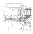
- reference sign 1 refers to an improved punching machine, which comprises a base frame 2 defining an upper horizontal table 3 for supporting metal sheets and bars undergoing machining operations.
- the base frame 2 supports an operating turret 4 inside which are housed the active punching components, namely a ram (not illustrated as it is familiar to industry technicians), a first support means 5 for at least one male punch holder 6, which means 5 is rotationally supported on the operating turret 4 in vertical alignment below said ram and is driven by a first motor assembly 100.
- the active punching components namely a ram (not illustrated as it is familiar to industry technicians)
- a second support means 7 which in turn supports a female die holder 8.
- the second support means 7 is vertically aligned with the first support means 5 and is also rotationally driven by a second respective motor assembly 200.
- an element 9 normally of circular shape and provided at the bottom with a tooth 109.
- the element 9 is capable of selecting at least one male punch 106 and pressing on the head thereof with the tooth 109.
- the element 9 is also rotationally driven by a respective third motor assembly 300.
- both the male punch holder 6 and the female die holder 8 can be driven by respective drive means 10 and 11, which are in synchronous rotational movement around a common vertical axis marked as dashed line "A", both with respect to the first support means 5 and the second support means 7.
- Both the first support means 5 and the second support means 7 consist of cylindrical elements 12 and 13 with a number of housings 14 and 15 which can hold a number of male punch holders 6 and at the same time an equal number of female die holders 8.
- both the male punch holder 6 and the female die holder 8 consist of cylindrical magazines, indicated respectively by 16 and 17, inside which can be housed, respectively, a pre-established number of male punches 106 and a corresponding number of female dies 108 which are vertically alignable with the respective male punches 106.
- Both the first support means 5 and the second support means 7 are provided with a number of hollow housings 14 and 15 capable of holding, in a rotationally free fashion, the cylindrical magazines 16 and 17 for male punches 106 and female dies 108, respectively.
- a means 18 for the transmission of rotational movement is provided between the male punch holders 6, the female die holders 8 and the respective rotational drive means 10 and 11.
- Both the male punch holders 6 and the female die holders 8 are provided perimetrically with a means 19 for mechanical coupling with their respective rotational drive means 10 and 11 and, where envisaged, with the means 18 for transmission of rotational movement.
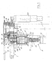
- the rotational drive means 10 and 11 for the cylindrical magazines 16 and 17 comprise respective motor/gear motor assemblies 20 and 21 fixed respectively to the operating turret 4 and the base frame 2. They are mutually synchronised.
- first and a second drive shaft indicated by reference signs 22 and 23.
- gear means 24 engageable with the mechanical coupling means 19 or, where present, with the interposed rotational movement transmission means 18.
- a support and guide means 25 is also provided for the aforesaid first and second drive shafts 22 and 23.
- the drive shafts are supported vertically, mutually coaxially and with their respective free ends concurrent. Furthermore, the motor assemblies 20 and 21 are controlled by a means 26 for angular indexing of rotation, consisting for example of zero-point sensors.
- the support and guide means 25 for the first drive shaft 22 comprises an abutment 27 projecting from the turret 4 of the punching machine 1, which abutment contains an axial cavity.
- the abutment 27 can accommodate the first drive shaft 22 in a coaxially traversing manner, with the interposition of an anti-friction means which is not illustrated because it would already be familiar to a person skilled in the art.
- the aforesaid means 25 further comprises a means 28 for axial retention of the first drive shaft 22 inside the abutment 27 and a means 29 for the rotationally free passage of the lower end of the shaft 22 through the rotating support means 5 of the male punch holder or holders 6.
- the means 29 for the rotationally free passage of the lower end of the shaft 22 through the rotating support means 5 comprises a through opening 31 formed centrally in said cylindrical element 12 with a number of housings and an anti-friction means 32 interposed between said lower end of the first drive shaft 22 and the opening 31, located in corresponding housings 33 formed therein.
- the means 28 for axial retention of the first drive shaft 22 in said abutment 27 comprises a rotationally fixed cylindrical liner 34 inside which the said first drive shaft 22 can be accommodated in a rotationally free manner and which is interposed between this and the internal cavity of the abutment 27, indicated as 127, and between this and the through opening 31.
- a radially projecting lower edge 37 capable of remaining stationary against the anti-friction means 32 and of axially retaining the liner inside the opening 31 when the first ring nut 36 is tightened.
- the means 30 for control of the axial clearance of the first drive shaft 22 comprises a box-shaped support 38 which is mounted integrally on the head of the liner 34 and is vertically traversable by the upper end of the first drive shaft 22, a second perimetral thread 39 formed on the latter substantially in the position of said box-like support 38 and a second ring nut 40 which can be retained in the box-like support 38 and can be screwed onto the aforesaid second thread 39. Tightening or loosening the second ring nut 40 again determines axial movement of the first drive shaft 22 relative to the liner 34.
- the support and guide means 25 for said second drive shaft 23 comprises a coupling flange 41 which projects from the base frame 2 of the punching machine 1 and which is provided with an axial cavity.
- the second drive shaft 23 can be accommodated in a coaxial traversing manner in said coupling flange, a dedicated axial retention means 42 being provided for the axial retention of said drive shaft inside the flange 41.
- the second drive shaft 23 is provided with a means 43 for the rotationally free passage of the upper end of said drive shaft through the second support means 7 for the cylindrical magazine(s) 17.
- the means 43 for the rotationally free passage of the upper end of said drive shaft through the second support means 7 comprises a cylindrical body 45, provided with an axial cavity and centrally engaged with the same cylindrical element 13 with a number of housings, an anti-friction means 46 interposed between the upper end of the second drive shaft 23 and the aforesaid cylindrical body 45, located in respective housings 47 formed therein.
- the means 42 for axial retention of the second drive shaft 23 in the coupling flange 41 comprises a second rotationally fixed cylindrical liner 48 equipped with an enlarged head 48a, inside which the aforesaid second drive shaft 23 can be housed in a rotationally free manner and which is interposed between this and the internal cavity of the coupling flange 41 and between this and the cylindrical body 45.
- a third ring nut 50 which normally rests against the coupling flange 41 and which is fitted coaxially onto the second liner 48. The tightening or loosening of the third ring nut 50 determines the axial movement of the second liner 48, pressing against the coupling flange 41.
- the means 44 for controlling the axial clearance of the second drive shaft 23 comprises a second box-shaped support 51, which is integrally mounted on the base of the second liner 48 and which is vertically traversable by the lower end of the second drive shaft 23, a fourth perimetral thread 52 formed on the second drive shaft 23 substantially in the position of the second box-shaped support 51 and a fourth ring nut 53 that can be retained in the latter and is capable of being screwed onto the fourth thread 52 to move the second drive shaft 23 axially with respect to the coupling flange 41.
- the rotational movement transmission means 19 consists of ring gears 54 which enclose the cylindrical magazines 16 and 17 in a perimetrically integral manner and which are engageable with the gear means 24.
- the rotational movement transmission means 18 consists of respective perimetrically toothed idle rollers 55 and 56 which are interposed between the gear means 24 and the ring gears 54.
- the gear means 24 consists of corresponding sprockets 57 and 58 which are engaged in a rotationally fixed manner to the concurrent respective ends of the first and second drive shafts 22 and 23.
- an elastic shock-absorbing means 59 is interposed between the coupling flange 41 and the cylindrical element 13, consisting in this case of at least one Belleville spring washer, or a group of Belleville spring washers, indicated by reference sign 60.
- the first support means 5 is normally equipped with a series of male punch holders 6 inside which are inserted corresponding cylindrical magazines 16, each of which can carry one or more male punches 106.
- the second support means 7 is equipped with an equivalent series of female die holders 8 inside which are inserted corresponding cylindrical magazines 17, each of which can carry a total number of female dies 108 equal to that of the male punches 106 of the vertically aligned cylindrical magazine 16.
- the first support means 5 and the second support means 7 are usually driven with synchronous rotation by the respective motor assemblies 100 and 200 in steps whose angular amplitude is controlled by the indexing means in such a way as to move the magazines 16 and 17, which have been selected for a given type of machining operation on a metal sheet or bar placed on the supporting table 3, into position below the ram.
- the cylindrical magazines 16 and 17 can be rotated inside their respective housings, around their coincident vertical axes, in such a way as to move a given punch 106 and the corresponding female die 108, selected out of those carried by each of them, to a predetermined position for machining on the metal sheet.
- the rotation of the aforesaid cylindrical magazines 16 and 17 is also controlled by angular indexing means (for example, zero-point sensors), indicated by the number 26 in the figures; the synchronous rotation of the cylindrical magazines 16 and 17 is achieved by way of the respective motor assemblies 20 and 21, which act on the ring gears 54 with which the aforesaid magazines 16 and 17 are perimetrically provided by way of the drive shafts 22 and 23, the sprockets 57 and 58 and the idle pulleys 55 and 56.
- angular indexing means for example, zero-point sensors
- the selector element 9 is finally activated, which likewise rotates above the cylindrical magazine 16 and moves the tooth 109 onto the head of the selected punch 106.
- This type of use may be required in order to perform a number of consecutive steps in complex punching operations at a single point on the metal sheet; for example, it may be necessary to execute a cross-shaped through profile: for this purpose a single punch 106 with an elongated rectangular profile and a corresponding female die 108 can be used.
- a first punching operation is performed to create one arm of the cross, then the magazines 16 and 17 are turned by a predetermined angle and a second punching operation is performed in such a way as to intersect with the first and thus create the required cross-shaped profile.
- the angular rotation of said cylindrical magazines 16 and 17 determines the angle at which the arms of the cross-shaped profile intersect.
- both drive shafts 22 and 23 are provided with the possibility of adjusting the axial clearance.
- the aforesaid adjustment is performed by turning the second ring nut 40, which, when tightened or loosened on the thread 39, produces axial movement of the shaft 22 pressing against the box-shaped support 38 in which it is retained, thereby adjusting its position.
- Both the shaft 22 and the shaft 23 rotate inside their respective liners 34 and 48, which in turn are fixed respectively to the abutment 27 projecting from the monobloc constituting the operating turret 4 of the punching machine 1 and to the flange 41, integral with the base frame 2.
- the first ring nut 36 and the third ring nut 50 when tightened on their respective threads 35 and 49 formed on said liners 34 and 48, fasten against the abutment 27 and the flange 41 the assemblies consisting of the drive shafts 22 and 23 and the respective motor assemblies 20 and 21, the opening 31 and the cylindrical body 45, thus securing everything respectively to the turret 4 and the base frame 2.
- the Belleville washer 60 interposed between the flange 41 and the enlarged head 48a of the second cylindrical liner 48, is able to absorb the strokes of the ram in such a way that they do not damage the cylindrical element 13 during the machining operation, and to perform precise vertical adjustment of the cylindrical element 13 itself.
Claims (24)
- Stanzmaschine mit einem Grundrahmen (2), der einen oberen horizontalen Arbeitstisch (3) zur Bearbeitung von Metallblechen und -Stäben bildet, mit einem Arbeitskopf (4), der oberhalb des Arbeitstisches (3) angeordnet ist und eine Stanzramme aufnimmt, einem ersten Träger (5) für mindestens einen Werkzeughalten, der mindestens ein männliches Stanzwerkzeug (106) enthält, wobei dieser erste Träger mittels eines zugeordneten ersten Antriebseinheit (100) rotatorisch um eine vertikale Achse (A) angetrieben ist und an dem Arbeitskopf (4) in vertikaler Ausrichtung unterhab der Stanzramme angeordnet ist, einem zweiten Träger (7) für einen Matrizenhalter, der in den Arbeitstisch in vertikaler Ausrichtung mit dem ersten Träger eingefügt ist und um die Achse (A) drehbar mittels einer entsprechenden zweiten Motoreinheit (200) antreibbar ist, die mit der ersten Motoreinheit (100) synchronisiert ist, mindestens einem Element (9), das zwischen der Stanzramme und dem Halter für das/die männliche(n) Stanzwerkzeug(e) vorgesehenen Halter (6) und dem Matrizenhalter (8) angeordnet ist und von einer zugeordneten dritten Antriebseinheit (300) rotatorisch angetrieben ist zur Selektion und zum Kontakt mit dem mindestens einen, männlichen Stanzwerkzeug (106), wobei der Halter (6) für die männlichen Werkzeuge und der Halter für weibliche Werkzeuge in synchroner Rotationsbewegung um eine gemeinsame vertikale Achse relativ zu dem ersten Träger (5) sowie dem zweiten Träger (7) angetrieben sind, dadurch gekennzeichnet, dass die jeweiligen Dreh-Antriebseinrichtungen (10, 11) Drehachsen haben, die koaxial bezüglich der gemeinsamen Drehachse (A) des ersten und des zweiten Trägers (5, 7) ausgerichtet sind.
- Stanzmaschine nach Anspruch 1, wobei der erste und der zweite Träger (5,7) aus zylindrischen Elementen (12, 13) bestehen, die eine Anzahl von Aufnahmeeinrichtungen (14, 15) zum Aufnehmen einer Anzahl von Haltern (6) für männliche Stanzwerkzeuge und Haltern (8) für weibliche Stanzwerkzeuge haben.
- Stanzmaschine nach Anspruch 2, wobei der Halter (6) für männliche und der Halter (8) für weibliche Stanzwerkzeuge jeweils aus einem zylindrischen Magazin (16, 17) zur Aufnahme jeweils einer definierten Anzahl von männlichen Stanzwerkzeugen (106) und einer entsprechenden Anzahl von weiblichen Stanzwerkzeugen (108) bestehen.
- Stanzmaschine nach Anspruch 1, Anspruch 2 oder Anspruch 3, wobei die erste Trägereinrichtung (5) und die zweite Trägereinrichtung (7) entsprechende axiale Aufnahmen (14, 15) umfassen, die zur Einführung rotatorisch frei drehbarer zylindrischer Magazine (16, 17) für männliche Stanzwerkzeugen (106) und für weibliche Stanzwerkzeuge (108) vorgesehen sind.
- Stanzmaschine nach einem der Ansprüche 1 bis 4, wobei eine Einrichtung (18) zur Übertragung der Drehbewegung zwischen dem Halter (6) für die männlichen Werkzeuge und dem Halter (8) für die weiblichen Stanzwerkzeuge, einerseits und den diesbezüglich vorgesehenen Dreh-Antriebsvorrichtungen (10, 11) vorgesehen ist.
- Stanzmaschine nach einem der Ansprüche 1 bis 5, wobei zylindrische Magazine (16, 17) zur Aufnahme männlicher Stanzwerkzeuge (106) und weiblicher Stanzwerkzeuge (108), die am Umfang mit einer Einrichtung (29) zur mechanischen Kopplung mit den rotatorischen Antriebeinrichtungen (100, 200) und/oder mit der Roations-BewegungsÜbertragungseinrichtung (18) versehen sind.
- Stanzmaschine nach einem der Ansprüche 1 bis 6, wobei die Dreh-Antriebseinrichtungen für die männlichen und weiblichen Stanzwerkzeuge vorgesehen des Weiteren umfassen:- Zugeordnete Motor/Cetriebemotoreinheiten (20, 21) , die jeweils an dem Arbeitskopf (4) und dem Grundrahmen (2) montiert und miteinander synchronisiert sind,- eine erste und eine zweite Antriebswelle (22, 23) die jeweils von der/den Motor/Getriebemotoreinheit(en) (20, 21) ausgehen,- eine entsprechende Getriebeeinrichtung (24), die mit den freien Enden der ersten und der zweiten Antriebswelle (22, 23) in Eingriff stehen und mit der Kupplungseinrichtung (19) und/oder mit der Übertragungseinrichtung (18) für die Drehbewegung in Eingriff bringbar sind und- eine Träger- und Führungseinrichtung (25) für die erste und die zweite Antriebswelle (22, 23).
- Stanzmaschine nach Anspruch 7, wobei die erste und die zweite Antriebswelle (22, 23) in koaxialer Anordnung vertikal abgestützt und mit ihren jeweiligen freien Enden gleichlaufend ausgebildet sind.
- Stanzmaschine nach Anspruch 7 oder Anspruch 8, wobei die Motoreinheiten (20, 21) mittels einer Einrichtung (26) für die Drehwinkelerfassung gesteuert sind.
- Stanzmaschine nach Anspruch 7, wobei die Träger- und Führungseinrichtung (25) der ersten Antriebswelle ein Widerlager (27) umfasst, das von dem Arbeitskopf (4) der Stanzmaschine ausgeht und mit einem axialen Hohlraum versehen ist, von dem die erste Antriebswelle (22) in einer den Hohlraum axial durchsetzenden Anordnung aufgenommen werden kann, des Weiteren eine Einrichtung (28) zur axialen Sicherung der ersten Antriebswelle (22) in dem Widerlager (27) hat, sowie eine Einrichtung (29) für einen frei drehbaren Hindurchtritt des unteren Abschnitts der ersten Antriebswelle (22) durch den ersten Träger (5) hindurch, der mindestens einen Halter (6) für ein männliches Stanzwerkzeug umfasst.
- Stanzmaschine nach Anspruch 10, wobei mindestens zwischen der ersten Antriebswelle (22) und der Stütz- und Führungseinrichtung (25) eine Einrichtung (30) zur Einstellung des axialen Spiels der ersten Antriebswelle (22) vorgesehen ist.
- Stanzmaschine nach Anspruch 10, wobei die Einrichtung (29) für den frei drehbaren Durchtritt der ersten Antriebswelle (22) des Weiteren eine Durchgangsöffnung (31) umfasst, die zentral in einem ersten der zylindrischen Elemente (12) mit einer Anzahl von Aufnahmen gebildet ist und mit einer reibungsmindernden Einrichtung (32) versehen ist, die zwischen dem unteren Ende der ersten Antriebswelle (22) und der Öffnung (31) angeordnet ist, die in den jeweiligen Aufnahmen (33) gebildet sind.
- Stanzmaschine nach Anspruch 10, wobei die Einrichtung (28) für die axiale Lagesicherung der ersten Antriebswelle (22) in den Widerlager (27) weiter eine drehfest angeordnete zylindrische Buchse (34) umfasst, innerhalb derer die genannte erste Antriebswelle (22) frei drehbar einsetzbar ist, wobei die Buchse zwischen der Antriebswelle und dem inneren Hohlraum (127) des Widerlagers (27) und zwischen diesem und der genannten Öffnung (33) angeordnet ist, des weiteren ein Gewinde (35) außenseitig an der Buchse oberhalb des Widerlagers (27) angeordnet ist, weiter eine erste Ringmutter (36) an dem Widerlager (27) abgestützt ist, die koaxial an der Buchse (34) abstützbar und auf das Gewinde (35) zur axialen Verschiebung der Buchse (34) aufschraubbar ist, die gegen das Widerlager (27) drückt und zur axialen Sicherung der Buchse (34) ein unterer Rand (37) vorgesehen ist, der von der Buchse (34) radial vorspringt und innerhalb der Öffnung (33) bei einem Anziehen der ersten Ringmutter (36) gegen den Öffnungsrand drückt.
- Stanzmaschine nach Anspruch 13, wobei die Einrichtung (30) zur Einstellung des axialen Spiels der ersten Antriebswelle (22) einen kastenförmigen Träger (38) umfasst, der an den Kopf der genannten Buchse (34) anmontiert ist, der vom oberen Ende der genannten ersten Antriebswelle (22) vertikal durchsetzt ist, weiter ein zweites Außengewinde (39) an der ersten Antriebswelle im wesentlichen in Höhe des kastenförmigen Trägers (38) angeordnet ist und eine zweite Ringmutter (40) in dem kastenförmigen Träger (38) gehalten und auf das genannte zweite Gewinde (39) aufschraubbar ist, um dadurch die erste Antriebswelle (22) gegenüber der Buchse (34) axial zu verschieben.
- Stanzmaschine nach einem der vorhergehenden Ansprüche 7 bis 14, wobei der Träger und die Führungseinrichtung (25) für die genannte zweite Antriebswelle (23) einen Koppelflansch (41) umfasst, der von dem Grundrahmen (2) der Stanzmaschine ausgeht und mit einem sich in axialer Richtung erstreckenden Hohlraum versehen ist, in dem die zweite Antriebswelle (23) in einer diesen axial durchsetzenden Anordnung aufnehmbar ist, des weiteren eine Einrichtung (42) zur axialen Sicherung der genannten zweiten Antriebswelle (23) in dem Flansch (41) vorgesehen ist sowie eine Einrichtung (43) vorgesehen ist, die einen frei drehbaren Durchtritt der zweiten Antriebswelle (23) durch den genannten Träger (7) ermöglicht, der für mindestens ein weiteres Stanzwerkzeug vorgesehenen Matrizenhalter (17) vorgesehen ist.
- Stanzmaschine nach Anspruch 15, wobei mindestens zwischen der zweiten Antriebswelle (23) und der genannten Träger- und Führungseinrichtung (25) eine Einrichtung (44) zur Einstellung des axialen Spiels der genannten zweiten Antriebswelle (23) vorgesehen ist.
- Stanzmaschine nach Anspruch 15 oder Anspruch 16, wobei die Einrichtung (43) für den frei drehbaren Durchtritt des oberen Endes der zweiten Antriebswelle (23) einen mit einem zentralen Hohlraum versehenen zylindrischen Körper (45) umfasst, der zentral mit zylindrischen Elementen in Eingriff steht, die eine Anzahl von Aufnahmen haben, und weiter eine Einrichtung (46) zur Reibungsminderung zwischen dem oberen Ende der genannten zweiten Antriebswelle (23) und dem genannten zylindrischen Körper (45) angeordnet ist, die in den darin gebildeten Aufnahmen angeordnet ist.
- Stanzmaschine nach Anspruch 15, wobei die Einrichtung (42) für die axiale Sicherung der zweiten Antriebswelle (23) in dem genannten Kopplungsflansch (41) eine zweite drehfest angeordnete zylindrische Buchse (48) umfasst, innerhalb derer die genannte zweite Antriebswelle frei drehbar einsetzbar ist, wobei die Buchse zwischen dieser und dem inneren Hohlraum des genannten Koppelflansches (41) sowie zwischen diesem und dem zylindrischen Körper (45) angeordnet ist, weiter ein drittes Außengewinde (49) an der zweiten Buchse (48) unterhalb des Kupplungsflansches (41) angeordnet ist und eine dritte Ringmutter (50) an dem Kupplungsflansch (41) abgestützt ist, die koaxial an der zweiten Buchse (48) festlegbar und zum Zweck einer axialen Bewegung der zweiten Buchse (48), die gegen den Kupplungsflansch (41) drückt, auf das dritte Gewinde (49) aufschraubbar ist.
- Stanzmaschine nach Anspruch 18, wobei die Einrichtung (44) zur Einstellung des axialen Spiels der zweiten Antriebswelle (33) einen zweiten, kastenförmigen Träger (51) umfasst, der an die Basis der zweiten Buchse (48) anmontiert ist und vertikal von dem unteren Ende der genannten zweiten Antriebswelle (23) durchquert wird, weiter ein viertes Außengewinde (52) vorgesehen ist, das an der zweiten Antriebswelle (23) im wesentlichen in Höhe des zweiten kastenförmigen Trägers (51) angeordnet ist, und eine vierte Ringmutter (63) vorgesehen ist, die von dem zweiten kastenförmigen Träger aufgenommen ist und schraubbar auf dem vierten Gewinde (52) geführt ist, um dadurch eine axiale Verschiebung der zweiten Antriebswelle (23) relativ zu dem Koppelflansch (41) zu erzielen.
- Stanzmaschine nach einem der vorhergehenden Ansprüche, wobei die Einrichtung (19) zur Übertragung rotatorischer Bewegungen aus Zahnrädern (54) besteht, welche die zylindrischen Magazine (16,17) außenseitig umschließen und mit der Getriebeeinrichtung (24) in Eingriff bringbar sind.
- Stanzmaschine nach Anspruch 20, dadurch gekennzeichnet, dass die zur Übertragung rotatorischer Bewegungen vorgesehene Übertragungseinrichtung (18) aus entsprechend am Umfang gezahnten frei laufenden Rollen (55,56) besteht, die zwischen der Getriebeeinrichtung (24) und den genannten Ringzahnrädern (54) einsetzbar sind.
- Stanzmaschine nach Anspruch 21, wobei die Getriebeeinrichtung (54) jeweils aus Zahnrädern (57,58) besteht, die drehfest mit den gleichlaufenden Endabschnitten der ersten und der zweiten Antriebswelle (22,23) in Eingriff stehen.
- Stanzmaschine nach einem der vorhergehenden Ansprüch1 18 bis 22, wobei eine elastische stoß-absorbierende Einrichtung (59) mindestens zwischen dem verbreiterten Kopf der genannten zweiten zylindrischen Buchse (48) und dem Kopplungsflansch (41) angeordnet ist.
- Stanzmaschine nach Anspruch 23, wobei die elastische stoß-absorbierende Einrichtung (59) aus mindestens einer Belleville-Tellerfeder (60) besteht.
Applications Claiming Priority (2)
| Application Number | Priority Date | Filing Date | Title |
|---|---|---|---|
| GB0300817 | 2003-01-14 | ||
| GB0300817A GB2397267B (en) | 2003-01-14 | 2003-01-14 | Punching machine |
Publications (2)
| Publication Number | Publication Date |
|---|---|
| EP1440743A1 EP1440743A1 (de) | 2004-07-28 |
| EP1440743B1 true EP1440743B1 (de) | 2007-06-27 |
Family
ID=9951131
Family Applications (1)
| Application Number | Title | Priority Date | Filing Date |
|---|---|---|---|
| EP04000450A Expired - Lifetime EP1440743B1 (de) | 2003-01-14 | 2004-01-12 | Stanzmaschine |
Country Status (7)
| Country | Link |
|---|---|
| US (1) | US20040169069A1 (de) |
| EP (1) | EP1440743B1 (de) |
| CN (1) | CN1313223C (de) |
| AT (1) | ATE365597T1 (de) |
| DE (1) | DE602004007168T2 (de) |
| GB (1) | GB2397267B (de) |
| RU (1) | RU2353458C2 (de) |
Families Citing this family (17)
| Publication number | Priority date | Publication date | Assignee | Title |
|---|---|---|---|---|
| KR200353165Y1 (ko) * | 2004-03-26 | 2004-06-14 | 디앤크래프트 주식회사 | 네 방향 펀칭이 가능한 펀치 |
| CN100349667C (zh) * | 2005-07-07 | 2007-11-21 | 陈柏梁 | 仿形液压冲孔机 |
| EP2210684B1 (de) * | 2009-01-27 | 2011-12-14 | TRUMPF Werkzeugmaschinen GmbH + Co. KG | Werkzeug für eine Stanzmaschine mit mehreren drehbaren Werkzeugeinsätzen |
| CN101791874B (zh) * | 2010-03-26 | 2012-10-10 | 重庆钢铁(集团)有限责任公司 | 自动冲压机床及其冲压方法 |
| CN102357585B (zh) * | 2011-07-26 | 2013-09-18 | 浙江晨丰灯头有限公司 | 一种灯头冲压机 |
| CN202224532U (zh) * | 2011-09-29 | 2012-05-23 | 广州市启泰模具工业有限公司 | 数控冲床模具上模装置 |
| DE102011087084A1 (de) * | 2011-11-25 | 2013-05-29 | Pass Stanztechnik Ag | Mehrfachwerkzeug |
| DK3003594T3 (en) * | 2013-05-27 | 2017-07-17 | Salvagnini Italia Spa | punching |
| TW201622970A (zh) * | 2014-07-29 | 2016-07-01 | 義大利薩瓦尼尼公司 | 衝壓裝置 |
| CN104525701B (zh) * | 2014-11-27 | 2017-05-10 | 丹阳正联知识产权运营管理有限公司 | 一种液压阀底板连续成型加工系列的多向打孔成型装置 |
| JP6503199B2 (ja) * | 2015-03-06 | 2019-04-17 | Jx金属株式会社 | 打抜き加工方法、及び、プレス成形品の製造方法 |
| CN106040818B (zh) * | 2016-07-08 | 2018-02-09 | 唐巧林 | 锂电池外壳拉伸成型机 |
| DE102016118175B4 (de) * | 2016-09-26 | 2018-08-23 | Trumpf Werkzeugmaschinen Gmbh & Co. Kg | Werkzeugmaschine und Verfahren zum Bearbeiten von plattenförmigen Werkstücken |
| CN106739109B (zh) * | 2016-12-28 | 2018-10-02 | 扬州工业职业技术学院 | 一种数控转塔冲床 |
| DE102017124334A1 (de) * | 2017-10-18 | 2019-04-18 | Hsf Automation Gmbh | Vorrichtung zum Nutenstanzen und Stanzsystem |
| US11033948B2 (en) | 2018-05-30 | 2021-06-15 | Mate Precision Technologies Inc. | Forming multi-tool |
| CN112692158A (zh) * | 2020-12-09 | 2021-04-23 | 安徽江淮汽车集团股份有限公司 | 轴销冲孔装置与冲孔方法 |
Family Cites Families (8)
| Publication number | Priority date | Publication date | Assignee | Title |
|---|---|---|---|---|
| US72456A (en) * | 1867-12-24 | Improvement in double cultivator-plow | ||
| US4658688A (en) * | 1985-09-13 | 1987-04-21 | Strippit/Di-Acro - Houdaille, Inc. | Rotary punch and die holders for turret punches |
| DE3720777C2 (de) * | 1987-06-24 | 1993-10-07 | Behrens Ag C | Revolverschneidpresse |
| JPH06126350A (ja) * | 1992-10-20 | 1994-05-10 | Murata Mach Ltd | タレットパンチプレス |
| GB2360727B (en) * | 2000-03-30 | 2004-02-04 | Tradewise Engineering Ltd | Modular unit for converting punching machines from single-punch to multiple-punch |
| GB2362122A (en) * | 2000-05-11 | 2001-11-14 | Tradewise Engineering Ltd | Quick extraction punch-holder adaptor for converting punching machines from a single punch to a multiple punch configuration |
| JP2002178054A (ja) * | 2000-12-11 | 2002-06-25 | Nisshinbo Ind Inc | パンチプレスの金型交換方法とこの交換方法を適用したパンチプレス |
| JP2002192260A (ja) * | 2000-12-27 | 2002-07-10 | Nisshinbo Ind Inc | パンチプレスおよびその加工方法 |
-
2003
- 2003-01-14 GB GB0300817A patent/GB2397267B/en not_active Expired - Fee Related
-
2004
- 2004-01-12 AT AT04000450T patent/ATE365597T1/de not_active IP Right Cessation
- 2004-01-12 EP EP04000450A patent/EP1440743B1/de not_active Expired - Lifetime
- 2004-01-12 DE DE602004007168T patent/DE602004007168T2/de not_active Expired - Lifetime
- 2004-01-13 RU RU2004101178/02A patent/RU2353458C2/ru not_active IP Right Cessation
- 2004-01-14 US US10/756,760 patent/US20040169069A1/en not_active Abandoned
- 2004-01-14 CN CNB2004100018302A patent/CN1313223C/zh not_active Expired - Fee Related
Also Published As
| Publication number | Publication date |
|---|---|
| CN1530190A (zh) | 2004-09-22 |
| RU2004101178A (ru) | 2005-06-20 |
| DE602004007168T2 (de) | 2008-03-06 |
| US20040169069A1 (en) | 2004-09-02 |
| RU2353458C2 (ru) | 2009-04-27 |
| GB2397267B (en) | 2005-09-14 |
| GB2397267A (en) | 2004-07-21 |
| CN1313223C (zh) | 2007-05-02 |
| DE602004007168D1 (de) | 2007-08-09 |
| GB0300817D0 (en) | 2003-02-12 |
| EP1440743A1 (de) | 2004-07-28 |
| ATE365597T1 (de) | 2007-07-15 |
Similar Documents
| Publication | Publication Date | Title |
|---|---|---|
| EP1440743B1 (de) | Stanzmaschine | |
| US6074330A (en) | Device for converting punch changing in punching machines from manual to quick and automatic | |
| US5810704A (en) | Turret punch press | |
| US8201435B2 (en) | Plate workpiece processing tools and machines | |
| CN1275715C (zh) | 将冲床从单凸模转变为多凸模的组合式装置 | |
| EP0256628A1 (de) | Teilvorrichtung | |
| CA2118568C (en) | Tool grinding machine | |
| JP3987677B2 (ja) | 押抜き・型打ち機 | |
| US4503694A (en) | Spring manufacturing machine equipped with two motors | |
| DE102011107467A1 (de) | Rundtaktmaschine | |
| CN217832041U (zh) | 一种自动切料机 | |
| US20020088319A1 (en) | Punch press and machining method of the punch press | |
| US5961379A (en) | Tool grinding machine | |
| JPH06218625A (ja) | タレットパンチのタップ装置 | |
| DE10158121B4 (de) | Schmiedemaschine mit einem Werkstück-Haltemechanismus und einem Schneidemechanismus, die durch die gleiche Antriebsvorrichtung angetrieben werden | |
| CN216137994U (zh) | 一种冲压机 | |
| JP5334881B2 (ja) | 打抜き機械に用いられる、回動可能な複数の工具挿入体を備えた工具 | |
| JPH06126533A (ja) | タレットパンチプレス | |
| CN215788103U (zh) | 一种数控打孔翻边机 | |
| RU70418U1 (ru) | Устройство для вырубки пазов в статорных и роторных пластинах электрических машин | |
| CN218341561U (zh) | 一种基于机械制造的零部件开孔装置 | |
| CN111958269B (zh) | 一种斜床身中心架 | |
| CN111922457B (zh) | 一种变速箱缸盖的自动攻丝装置 | |
| US4488841A (en) | Apparatus for machining workpieces to a predetermined shape | |
| CN117086174B (zh) | 一种汽车零部件生产多工位冲压设备 |
Legal Events
| Date | Code | Title | Description |
|---|---|---|---|
| PUAI | Public reference made under article 153(3) epc to a published international application that has entered the european phase |
Free format text: ORIGINAL CODE: 0009012 |
|
| AK | Designated contracting states |
Kind code of ref document: A1 Designated state(s): AT BE BG CH CY CZ DE DK EE ES FI FR GB GR HU IE IT LI LU MC NL PT RO SE SI SK TR |
|
| AX | Request for extension of the european patent |
Extension state: AL LT LV MK |
|
| 17P | Request for examination filed |
Effective date: 20050118 |
|
| AKX | Designation fees paid |
Designated state(s): AT BE BG CH CY CZ DE DK EE ES FI FR GB GR HU IE IT LI LU MC NL PT RO SE SI SK TR |
|
| 17Q | First examination report despatched |
Effective date: 20050503 |
|
| GRAP | Despatch of communication of intention to grant a patent |
Free format text: ORIGINAL CODE: EPIDOSNIGR1 |
|
| GRAS | Grant fee paid |
Free format text: ORIGINAL CODE: EPIDOSNIGR3 |
|
| GRAA | (expected) grant |
Free format text: ORIGINAL CODE: 0009210 |
|
| AK | Designated contracting states |
Kind code of ref document: B1 Designated state(s): AT BE BG CH CY CZ DE DK EE ES FI FR GB GR HU IE IT LI LU MC NL PT RO SE SI SK TR |
|
| REG | Reference to a national code |
Ref country code: GB Ref legal event code: FG4D |
|
| REG | Reference to a national code |
Ref country code: CH Ref legal event code: EP |
|
| REG | Reference to a national code |
Ref country code: IE Ref legal event code: FG4D |
|
| REF | Corresponds to: |
Ref document number: 602004007168 Country of ref document: DE Date of ref document: 20070809 Kind code of ref document: P |
|
| PG25 | Lapsed in a contracting state [announced via postgrant information from national office to epo] |
Ref country code: SE Free format text: LAPSE BECAUSE OF FAILURE TO SUBMIT A TRANSLATION OF THE DESCRIPTION OR TO PAY THE FEE WITHIN THE PRESCRIBED TIME-LIMIT Effective date: 20070927 |
|
| PG25 | Lapsed in a contracting state [announced via postgrant information from national office to epo] |
Ref country code: AT Free format text: LAPSE BECAUSE OF FAILURE TO SUBMIT A TRANSLATION OF THE DESCRIPTION OR TO PAY THE FEE WITHIN THE PRESCRIBED TIME-LIMIT Effective date: 20070627 |
|
| NLV1 | Nl: lapsed or annulled due to failure to fulfill the requirements of art. 29p and 29m of the patents act | ||
| REG | Reference to a national code |
Ref country code: CH Ref legal event code: PL |
|
| PG25 | Lapsed in a contracting state [announced via postgrant information from national office to epo] |
Ref country code: BE Free format text: LAPSE BECAUSE OF FAILURE TO SUBMIT A TRANSLATION OF THE DESCRIPTION OR TO PAY THE FEE WITHIN THE PRESCRIBED TIME-LIMIT Effective date: 20070627 |
|
| PG25 | Lapsed in a contracting state [announced via postgrant information from national office to epo] |
Ref country code: PT Free format text: LAPSE BECAUSE OF FAILURE TO SUBMIT A TRANSLATION OF THE DESCRIPTION OR TO PAY THE FEE WITHIN THE PRESCRIBED TIME-LIMIT Effective date: 20071127 Ref country code: SI Free format text: LAPSE BECAUSE OF FAILURE TO SUBMIT A TRANSLATION OF THE DESCRIPTION OR TO PAY THE FEE WITHIN THE PRESCRIBED TIME-LIMIT Effective date: 20070627 Ref country code: BG Free format text: LAPSE BECAUSE OF FAILURE TO SUBMIT A TRANSLATION OF THE DESCRIPTION OR TO PAY THE FEE WITHIN THE PRESCRIBED TIME-LIMIT Effective date: 20070927 Ref country code: ES Free format text: LAPSE BECAUSE OF FAILURE TO SUBMIT A TRANSLATION OF THE DESCRIPTION OR TO PAY THE FEE WITHIN THE PRESCRIBED TIME-LIMIT Effective date: 20071008 Ref country code: NL Free format text: LAPSE BECAUSE OF FAILURE TO SUBMIT A TRANSLATION OF THE DESCRIPTION OR TO PAY THE FEE WITHIN THE PRESCRIBED TIME-LIMIT Effective date: 20070627 Ref country code: CZ Free format text: LAPSE BECAUSE OF FAILURE TO SUBMIT A TRANSLATION OF THE DESCRIPTION OR TO PAY THE FEE WITHIN THE PRESCRIBED TIME-LIMIT Effective date: 20070627 |
|
| EN | Fr: translation not filed | ||
| PG25 | Lapsed in a contracting state [announced via postgrant information from national office to epo] |
Ref country code: CH Free format text: LAPSE BECAUSE OF FAILURE TO SUBMIT A TRANSLATION OF THE DESCRIPTION OR TO PAY THE FEE WITHIN THE PRESCRIBED TIME-LIMIT Effective date: 20070627 Ref country code: SK Free format text: LAPSE BECAUSE OF FAILURE TO SUBMIT A TRANSLATION OF THE DESCRIPTION OR TO PAY THE FEE WITHIN THE PRESCRIBED TIME-LIMIT Effective date: 20070627 Ref country code: LI Free format text: LAPSE BECAUSE OF FAILURE TO SUBMIT A TRANSLATION OF THE DESCRIPTION OR TO PAY THE FEE WITHIN THE PRESCRIBED TIME-LIMIT Effective date: 20070627 |
|
| PG25 | Lapsed in a contracting state [announced via postgrant information from national office to epo] |
Ref country code: GR Free format text: LAPSE BECAUSE OF FAILURE TO SUBMIT A TRANSLATION OF THE DESCRIPTION OR TO PAY THE FEE WITHIN THE PRESCRIBED TIME-LIMIT Effective date: 20070928 Ref country code: DK Free format text: LAPSE BECAUSE OF FAILURE TO SUBMIT A TRANSLATION OF THE DESCRIPTION OR TO PAY THE FEE WITHIN THE PRESCRIBED TIME-LIMIT Effective date: 20070627 |
|
| PLBE | No opposition filed within time limit |
Free format text: ORIGINAL CODE: 0009261 |
|
| STAA | Information on the status of an ep patent application or granted ep patent |
Free format text: STATUS: NO OPPOSITION FILED WITHIN TIME LIMIT |
|
| PG25 | Lapsed in a contracting state [announced via postgrant information from national office to epo] |
Ref country code: RO Free format text: LAPSE BECAUSE OF FAILURE TO SUBMIT A TRANSLATION OF THE DESCRIPTION OR TO PAY THE FEE WITHIN THE PRESCRIBED TIME-LIMIT Effective date: 20070627 |
|
| 26N | No opposition filed |
Effective date: 20080328 |
|
| PG25 | Lapsed in a contracting state [announced via postgrant information from national office to epo] |
Ref country code: FR Free format text: LAPSE BECAUSE OF FAILURE TO SUBMIT A TRANSLATION OF THE DESCRIPTION OR TO PAY THE FEE WITHIN THE PRESCRIBED TIME-LIMIT Effective date: 20080222 |
|
| PG25 | Lapsed in a contracting state [announced via postgrant information from national office to epo] |
Ref country code: MC Free format text: LAPSE BECAUSE OF NON-PAYMENT OF DUE FEES Effective date: 20080131 |
|
| GBPC | Gb: european patent ceased through non-payment of renewal fee |
Effective date: 20080112 |
|
| PG25 | Lapsed in a contracting state [announced via postgrant information from national office to epo] |
Ref country code: DE Free format text: LAPSE BECAUSE OF NON-PAYMENT OF DUE FEES Effective date: 20080801 |
|
| PG25 | Lapsed in a contracting state [announced via postgrant information from national office to epo] |
Ref country code: GB Free format text: LAPSE BECAUSE OF NON-PAYMENT OF DUE FEES Effective date: 20080112 |
|
| PG25 | Lapsed in a contracting state [announced via postgrant information from national office to epo] |
Ref country code: IE Free format text: LAPSE BECAUSE OF NON-PAYMENT OF DUE FEES Effective date: 20080114 Ref country code: EE Free format text: LAPSE BECAUSE OF FAILURE TO SUBMIT A TRANSLATION OF THE DESCRIPTION OR TO PAY THE FEE WITHIN THE PRESCRIBED TIME-LIMIT Effective date: 20070627 |
|
| PG25 | Lapsed in a contracting state [announced via postgrant information from national office to epo] |
Ref country code: FI Free format text: LAPSE BECAUSE OF FAILURE TO SUBMIT A TRANSLATION OF THE DESCRIPTION OR TO PAY THE FEE WITHIN THE PRESCRIBED TIME-LIMIT Effective date: 20070627 |
|
| PGRI | Patent reinstated in contracting state [announced from national office to epo] |
Ref country code: DE Effective date: 20090127 |
|
| PG25 | Lapsed in a contracting state [announced via postgrant information from national office to epo] |
Ref country code: CY Free format text: LAPSE BECAUSE OF FAILURE TO SUBMIT A TRANSLATION OF THE DESCRIPTION OR TO PAY THE FEE WITHIN THE PRESCRIBED TIME-LIMIT Effective date: 20070627 |
|
| PG25 | Lapsed in a contracting state [announced via postgrant information from national office to epo] |
Ref country code: LU Free format text: LAPSE BECAUSE OF NON-PAYMENT OF DUE FEES Effective date: 20080112 Ref country code: HU Free format text: LAPSE BECAUSE OF FAILURE TO SUBMIT A TRANSLATION OF THE DESCRIPTION OR TO PAY THE FEE WITHIN THE PRESCRIBED TIME-LIMIT Effective date: 20071228 |
|
| PGFP | Annual fee paid to national office [announced via postgrant information from national office to epo] |
Ref country code: DE Payment date: 20170215 Year of fee payment: 14 |
|
| PGFP | Annual fee paid to national office [announced via postgrant information from national office to epo] |
Ref country code: TR Payment date: 20170105 Year of fee payment: 14 Ref country code: IT Payment date: 20170126 Year of fee payment: 14 |
|
| REG | Reference to a national code |
Ref country code: DE Ref legal event code: R119 Ref document number: 602004007168 Country of ref document: DE |
|
| PG25 | Lapsed in a contracting state [announced via postgrant information from national office to epo] |
Ref country code: DE Free format text: LAPSE BECAUSE OF NON-PAYMENT OF DUE FEES Effective date: 20180801 |
|
| PG25 | Lapsed in a contracting state [announced via postgrant information from national office to epo] |
Ref country code: IT Free format text: LAPSE BECAUSE OF NON-PAYMENT OF DUE FEES Effective date: 20180112 |
|
| PG25 | Lapsed in a contracting state [announced via postgrant information from national office to epo] |
Ref country code: TR Free format text: LAPSE BECAUSE OF NON-PAYMENT OF DUE FEES Effective date: 20180112 |