EP1439268A2 - Duschanordnung - Google Patents
Duschanordnung Download PDFInfo
- Publication number
- EP1439268A2 EP1439268A2 EP03029833A EP03029833A EP1439268A2 EP 1439268 A2 EP1439268 A2 EP 1439268A2 EP 03029833 A EP03029833 A EP 03029833A EP 03029833 A EP03029833 A EP 03029833A EP 1439268 A2 EP1439268 A2 EP 1439268A2
- Authority
- EP
- European Patent Office
- Prior art keywords
- holder
- mounting arrangement
- arrangement according
- additional element
- wall
- Prior art date
- Legal status (The legal status is an assumption and is not a legal conclusion. Google has not performed a legal analysis and makes no representation as to the accuracy of the status listed.)
- Granted
Links
Images


Classifications
-
- E—FIXED CONSTRUCTIONS
- E03—WATER SUPPLY; SEWERAGE
- E03C—DOMESTIC PLUMBING INSTALLATIONS FOR FRESH WATER OR WASTE WATER; SINKS
- E03C1/00—Domestic plumbing installations for fresh water or waste water; Sinks
- E03C1/02—Plumbing installations for fresh water
- E03C1/06—Devices for suspending or supporting the supply pipe or supply hose of a shower-bath
-
- A—HUMAN NECESSITIES
- A47—FURNITURE; DOMESTIC ARTICLES OR APPLIANCES; COFFEE MILLS; SPICE MILLS; SUCTION CLEANERS IN GENERAL
- A47K—SANITARY EQUIPMENT; ACCESSORIES THEREFOR, e.g. TOILET ACCESSORIES
- A47K3/00—Baths; Showers; Appurtenances therefor
- A47K3/28—Showers or bathing douches
- A47K3/281—Accessories for showers or bathing douches, e.g. cleaning devices for walls or floors of showers
-
- E—FIXED CONSTRUCTIONS
- E03—WATER SUPPLY; SEWERAGE
- E03C—DOMESTIC PLUMBING INSTALLATIONS FOR FRESH WATER OR WASTE WATER; SINKS
- E03C1/00—Domestic plumbing installations for fresh water or waste water; Sinks
- E03C1/02—Plumbing installations for fresh water
- E03C1/06—Devices for suspending or supporting the supply pipe or supply hose of a shower-bath
- E03C1/066—Devices for suspending or supporting the supply pipe or supply hose of a shower-bath allowing height adjustment of shower head
Definitions
- the invention is based on a shower arrangement.
- shower arrangements It is often desired to install additional elements that for storing soap, bottles with shower additives or other Aids are intended or intended.
- Wall bars can be used, such additional elements For example, be attached to the wall bar.
- additional elements usually attached to the side.
- the holders for additional elements can be displaced along the wall bar.
- the additional elements When mounted in front of a flat wall, the additional elements are like this appropriate that they are directed as far to the side, what about causes them to be oriented just in front of the wall surface.
- an adapter for shower head suspensions (DE-U-29914810).
- a carrier body can be attached, for example, the Hanging hangers can be used.
- a hanging arrangement for holding toiletries (DE-U 20003623).
- the filing can be in any Angular position relative to the axis of the rod are attached. It several such shelves can be attached to the bar, which can then assume different angular positions.
- the invention is based on the object, a way to accommodate of additional elements for sanitary needs to create at which the Attachment in front of a flat wall as well as not flat Jobs without difficulty is possible.
- the one position of the additional element is designed so that they Attachment of the holder in front of a flat wall corresponds.
- the holder in another place be attached, either in a corner or in the area of a Corner of a bathroom, a shower cubicle or the like or also on a concavely curved side wall of a shower cubicle, so the additional element can be arranged in a position that the Attachment of the holder at this point allows.
- the two different positions through distinguish a linear movement of the additional element. Especially It makes sense, however, that the two possible positions through a different angular position of the additional element opposite the holder and / or relative to the location where the holder is attached will differ. In particular, it should be a different Angular position about a vertical axis.
- the additional element in the at least two positions with the holder is connectable. Around to transfer the additional element from one to the other position, It would therefore be necessary to remove the additional element and in the another position.
- the additional element opposite The holder is designed to be pivotable.
- pivot axis through the Edge region of the additional element passes, or even outside the edge of the additional element is located.
- the holder on which the additional element with the connecting device can be attached for example, directly to a wall or a Partition be attached.
- the holder can have a double function take over, namely for holding a wall bar or a Serve wall bar profiles. In this latter case, the holder connected to the wall bar.
- the Holder not connected to the wall but only to the wall bar is, so that by the wall rod fastened by other means is held.
- the holder can in a further development of the invention also on a slide be fixed, which is designed to be displaceable along the wall bar.
- the holder may also be part of this slider.
- At least two positions can be provided that one position of an assembly in front of a continuous plane Area and the other position of an arrangement in a solid angle equivalent.
- the holder in the solid angle for example be oriented so that it is directed in the direction of the bisector is. It is also possible that he also in a solid angle is still attached to the one flat wall, so unbalanced extends to the bisector.
- the holder has two preferably symmetrically arranged additional elements has, in each case alone or jointly between in each case at least two positions can be changed.
- the holder For pivotal mounting of the holder can be a receptacle for a Having approach of the additional element.
- the swiveling storage Optionally, it can also pivot around two parallel axes exhibit.
- the additional element can be fixed, so not removable with be connected to the holder, or even removable.
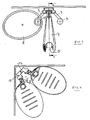
- a wall bar 1 is shown, in the vertical direction runs and attached, for example, on the wall of a shower cubicle is.
- the wall bar 1 is a profile with an open towards the front undercut groove 2 is formed.
- a slider 3 is displaceable guided.
- a boom 4 is a vertical Axis pivotally mounted.
- the boom 4 includes a cone holder 5, which is a horizontal Axis is pivotally mounted.
- the cone holder 5 serves to accommodate and attachment of the handle end of a hand shower, whose Hose is then threaded through the groove 2 and down hangs.
- the wall bar 1 In the area of the lower end, the wall bar 1 by means of a holder 6 attached.
- the holder 6 is on the one hand attached to the wall and on the other hand connected to the wall bar 1. So he serves for attachment the wall bar 1.
- the holder 6 contains two obliquely forward protruding arms 7, at the ends of each a soap dish 8 attached is. The attachment is done eccentrically to the soap dish 8.
- the wall bar 1 is in front of a flat continuous Wall attached.
- the two soap dishes 8 are outward oriented and lie with its edge just before the surface of the wall.
- FIG. 2 shows a section through the arrangement of FIG. 1.
- Am End of the arm 7 of the holder 6 is an upwardly projecting bearing pin 9 trained. This journal engages in a corresponding cylindrical Sack opening a storage 10 of the soap dish 8 a.
- Warehousing 10 is a shape of the soap dish 8 and extends in the upper Area flush with the upper edge 11 of the soap dish 8.
- the soap dish 8 has in its bottom 12 some holes for draining water on.
- Figure 3 shows the top view of the arrangement of Figure 1, wherein the better representation of one of the two soap dishes 8 is removed.
- the storage 10 of the oval soap dish 8 in plan view is in the edge region the soap dish 8 is formed, so that the soap dish 8 to the pivoted by the bearing 10 axis pivoted to near the wall can be. From this position shown, the soap dish 8, if it is located below the boom 4, from be pivoted away from the wall, so that they are then in a lateral direction has a different footprint than in the position shown.
- FIGs 4 and 5 show a second embodiment, in which a Holder 16 is provided, which is used independently of a wall bar 1 can be.
- the holder 16 has in cross-section or in the Top view of a web 17, the flat back used for this purpose be screwed to a wall, as in FIG. 5 is shown.
- From the web 17 from two arms 18 protrude obliquely in front, similar to the arms 7 of the embodiment according to FIGS. 1 to 3.
- At the front end of the arms 18 in turn is a storage for a tray arranged, which may be formed in the same way as the storage in the embodiment of Figure 1 and 3.
- the two storage trays 8 can be identical to the storage trays 8 of first embodiment.
- Figure 4 shows the position in which both soap dishes 8 are pivoted towards each other until they touch. In In this case, their outsides run so that they are exactly in one Room corner with an angle of 90 ° fit. In this position can the holder 16 is screwed directly into the wall corner with the aid of an adapter become.
- Such a holder as shown in Figures 4 and 5, can also in Situations are used where the angle between two wall areas are greater than the 90 ° shown in Figure 4.
- the Ausklapp ein the two trays 8 can be adapted to the geometry.
- such a holder can be mounted in a shower cubicle be, which has a concave curved boundary wall.
Landscapes
- Health & Medical Sciences (AREA)
- Public Health (AREA)
- Life Sciences & Earth Sciences (AREA)
- Engineering & Computer Science (AREA)
- Hydrology & Water Resources (AREA)
- Water Supply & Treatment (AREA)
- Epidemiology (AREA)
- General Health & Medical Sciences (AREA)
- Domestic Plumbing Installations (AREA)
- Bathtubs, Showers, And Their Attachments (AREA)
- Catching Or Destruction (AREA)
- Special Spraying Apparatus (AREA)
Abstract
Description
- Fig. 1
- schematisch eine Ansicht einer Wandstange mit einer Brausehalterung und zwei Zusatzelementen;
- Fig. 2
- einen Schnitt durch die Anordnung der Figur 1;
- Fig. 3
- eine Draufsicht auf eine zweite Ausführungsform;
- Fig. 4
- eine Draufsicht auf eine Anordnung in einer Raumecke;
- Fig. 5
- eine Draufsicht auf einen Halter der Figur 4 vor einer ebenen Wand.
Claims (12)
- Halterungsanordnung, mit1.1 einem insbesondere ortsfest anbringbaren Halter (6, 16),1.2 mindestens einem Zusatzelement (8), sowie mit1.3 einem Verbindungsmittel zwischen dem Halter (6, 16) und dem Zusatzelement (8), wobei1.4 das Zusatzelement (8) mindestens zwei verschiedene Positionen unterschiedlichen seitlichen Platzbedarfs gegenüber dem Halter bzw. der Stelle, an der er angebracht wird, einnehmen kann.
- Halterungsanordnung nach Anspruch 1, bei der sich die beiden Positionen durch eine unterschiedliche Winkelstellung um eine vertikale Achse unterscheiden.
- Halterungsanordnung nach Anspruch 1 oder 2, bei der das Zusatzelement (8) in den Positionen mit dem Halter, (6, 16) verbindbar ist.
- Halterungsanordnung nach einem der vorhergehenden Ansprüche, bei der das Zusatzelement (8) gegenüber dem Halter (6, 16) verschwenkbar ist.
- Halterungsanordnung nach Anspruch 4, bei der die Schwenkachse durch den Randbereich des Zusatzelements (8) verläuft.
- Halterungsanordnung nach Anspruch 4, bei der die Schwenkachse außerhalb des Zusatzelements (8) liegt.
- Halterungsanordnung nach einem der vorhergehenden Ansprüche, bei der der Halter (6, 16) an einer Wand befestigbar ist.
- Halterungsanordnung nach einem der vorhergehenden Ansprüche, bei der der Halter (6, 16) an einer Wandstange (1) befestigbar ist.
- Halterungsanordnung nach einem der vorhergehenden Ansprüche, bei der der Halter an einem Schieber befestigbar ist bzw. einen Teil eines Schiebers bildet.
- Halterungsanordnung nach einem der vorhergehenden Ansprüche, bei der die eine Position einer Anordnung vor einer durchgehenden Fläche und die andere Position einer Anordnung in einem Raumwinkel entspricht.
- Halterungsanordnung nach einem der vorhergehenden Ansprüche, mit zwei vorzugsweise symmetrisch angeordneten Zusatzelementen (8).
- Halterungsanordnung nach einem der Ansprüche 4 bis 11, bei der zur schwenkbaren Lagerung des mindestens einen Zusatzelements (8) der Halter (6, 16) eine Aufnahme für einen Ansatz (10) des Zusatzelements (8) aufweist.
Applications Claiming Priority (2)
| Application Number | Priority Date | Filing Date | Title |
|---|---|---|---|
| DE2003102348 DE10302348A1 (de) | 2003-01-16 | 2003-01-16 | Duschandordnung |
| DE10302348 | 2003-01-16 |
Publications (3)
| Publication Number | Publication Date |
|---|---|
| EP1439268A2 true EP1439268A2 (de) | 2004-07-21 |
| EP1439268A3 EP1439268A3 (de) | 2005-01-26 |
| EP1439268B1 EP1439268B1 (de) | 2012-08-22 |
Family
ID=32520062
Family Applications (1)
| Application Number | Title | Priority Date | Filing Date |
|---|---|---|---|
| EP20030029833 Expired - Lifetime EP1439268B1 (de) | 2003-01-16 | 2003-12-24 | Halterungsanordnung für den Sanitärbereich |
Country Status (3)
| Country | Link |
|---|---|
| EP (1) | EP1439268B1 (de) |
| CN (1) | CN1303292C (de) |
| DE (1) | DE10302348A1 (de) |
Families Citing this family (3)
| Publication number | Priority date | Publication date | Assignee | Title |
|---|---|---|---|---|
| DE202008011405U1 (de) * | 2008-08-27 | 2009-10-08 | Altura Leiden Holding B.V. | Duschkabine |
| DE102022202631A1 (de) * | 2022-03-17 | 2023-09-21 | Hansgrohe Se | Sanitäre Wandhalterungsvorrichtung |
| CN220001600U (zh) * | 2023-03-29 | 2023-11-14 | 福建西河卫浴科技有限公司 | 一种沐浴置物装置 |
Citations (3)
| Publication number | Priority date | Publication date | Assignee | Title |
|---|---|---|---|---|
| DE19650000A1 (de) | 1996-12-03 | 1998-06-04 | Gernot Hirse | Anordnung zur Anbringung von Hilfsgeräten oder Hilfsarmaturen in einem Dusch- oder Wannenraum |
| DE29914810U1 (de) | 1999-08-25 | 1999-12-23 | Veith, Rudolf, 42549 Velbert | Adapter für Duschkopfaufhängungen |
| DE20003623U1 (de) | 2000-02-28 | 2000-06-21 | Chen, Te-Sen, Changhua | Hängeanordnung zum Halten von Toilettenartikeln |
Family Cites Families (9)
| Publication number | Priority date | Publication date | Assignee | Title |
|---|---|---|---|---|
| US2174650A (en) * | 1938-09-17 | 1939-10-03 | George B Bentz | Combined floor and tub stand |
| FR1520721A (fr) * | 1967-03-02 | 1968-04-12 | Anciens Etablissements Queroy | Porte-serviettes |
| US3837013A (en) * | 1973-04-26 | 1974-09-24 | O Davis | Movable shower head and soap tray assembly |
| DE8130060U1 (de) * | 1981-10-14 | 1982-02-17 | PAS Patent Administration & Service GmbH, 8000 München | Vorrichtung zur Halterung von Duscharmaturen |
| GB2196840B (en) * | 1986-11-05 | 1990-05-23 | Fairform Mfg Co Ltd | Riser rail assembly for a shower fitting |
| DE4237738A1 (de) * | 1992-11-09 | 1994-05-11 | Grohe Armaturen Friedrich | Wandstange für Brausen |
| JP2724671B2 (ja) * | 1993-12-25 | 1998-03-09 | アロン化成株式会社 | 浴用備品置き棚 |
| DE19620282A1 (de) * | 1996-05-21 | 1997-11-27 | Arno Thamm | Haltestange zur Halterung einer Duschbrause |
| AT5633U1 (de) * | 2001-11-05 | 2002-09-25 | Neher Bad & Wellness Systems G | Brause |
-
2003
- 2003-01-16 DE DE2003102348 patent/DE10302348A1/de not_active Withdrawn
- 2003-12-24 EP EP20030029833 patent/EP1439268B1/de not_active Expired - Lifetime
-
2004
- 2004-01-16 CN CNB2004100074213A patent/CN1303292C/zh not_active Expired - Fee Related
Patent Citations (3)
| Publication number | Priority date | Publication date | Assignee | Title |
|---|---|---|---|---|
| DE19650000A1 (de) | 1996-12-03 | 1998-06-04 | Gernot Hirse | Anordnung zur Anbringung von Hilfsgeräten oder Hilfsarmaturen in einem Dusch- oder Wannenraum |
| DE29914810U1 (de) | 1999-08-25 | 1999-12-23 | Veith, Rudolf, 42549 Velbert | Adapter für Duschkopfaufhängungen |
| DE20003623U1 (de) | 2000-02-28 | 2000-06-21 | Chen, Te-Sen, Changhua | Hängeanordnung zum Halten von Toilettenartikeln |
Also Published As
| Publication number | Publication date |
|---|---|
| CN1303292C (zh) | 2007-03-07 |
| CN1517497A (zh) | 2004-08-04 |
| EP1439268B1 (de) | 2012-08-22 |
| DE10302348A1 (de) | 2004-07-29 |
| EP1439268A3 (de) | 2005-01-26 |
Similar Documents
| Publication | Publication Date | Title |
|---|---|---|
| EP3384568B1 (de) | Rahmenprofil für ein rahmengestell eines schaltschranks und ein entsprechendes rahmengestell | |
| EP3000655A2 (de) | Vorrichtung zum festlegen von ladungsgegenständen | |
| EP1439268B1 (de) | Halterungsanordnung für den Sanitärbereich | |
| DE102013003822B3 (de) | Armaturablage | |
| DE10260207B4 (de) | Sanitärhalterung | |
| DE202019101555U1 (de) | Duschablage | |
| AT520804B1 (de) | Doppelwandige Schubladenseitenwand | |
| DE102018130974A1 (de) | Möbelkomponente und Verfahren zur Herstellung | |
| DE2721348C2 (de) | Halterung für WC-Desodorantien | |
| EP4103015A1 (de) | Aufhängevorrichtung und primärträger | |
| EP3569777B1 (de) | Sanitäres tragsystem | |
| AT509281B1 (de) | Duschtrennwand oder -kabine | |
| EP0733321A1 (de) | Haltevorrichtung für eine unter einem Tisch oder dergleichen zu befestigende Tragwanne | |
| EP3033980B1 (de) | Verschiebbare glaswand | |
| DE9101068U1 (de) | Trennwand, insbesondere für Messe- und Ausstellungsstände | |
| DE3400153A1 (de) | Vorrichtung zur aufnahme von abfall | |
| CH633754A5 (en) | Removable folding panel for a flatbed body of a vehicle | |
| DE29919446U1 (de) | Haltevorrichtung für eine Deckenrandschalung | |
| EP1428941A2 (de) | Anordnung zur Anbringung eines Sanitärgegenstands | |
| DE1922048C3 (de) | Möbel mit einem flachen Schrankkasten | |
| DE29511165U1 (de) | Flanscheinrichtung einer Rolladenvorrichtung | |
| DE19746959B4 (de) | Vorrichtung zum Zugänglichmachen einer hinter einem Spiegel angeordneten Spendereinrichtung | |
| AT414207B (de) | Aufhängevorrichtung für einen duschvorhang | |
| DE2325571C3 (de) | I nstallatlonskasten | |
| DE29923413U1 (de) | Duschabtrennung |
Legal Events
| Date | Code | Title | Description |
|---|---|---|---|
| PUAI | Public reference made under article 153(3) epc to a published international application that has entered the european phase |
Free format text: ORIGINAL CODE: 0009012 |
|
| AK | Designated contracting states |
Kind code of ref document: A2 Designated state(s): AT BE BG CH CY CZ DE DK EE ES FI FR GB GR HU IE IT LI LU MC NL PT RO SE SI SK TR |
|
| AX | Request for extension of the european patent |
Extension state: AL LT LV MK |
|
| PUAL | Search report despatched |
Free format text: ORIGINAL CODE: 0009013 |
|
| AK | Designated contracting states |
Kind code of ref document: A3 Designated state(s): AT BE BG CH CY CZ DE DK EE ES FI FR GB GR HU IE IT LI LU MC NL PT RO SE SI SK TR |
|
| AX | Request for extension of the european patent |
Extension state: AL LT LV MK |
|
| REG | Reference to a national code |
Ref country code: HK Ref legal event code: DE Ref document number: 1066253 Country of ref document: HK |
|
| 17P | Request for examination filed |
Effective date: 20050513 |
|
| AKX | Designation fees paid |
Designated state(s): AT BE BG CH CY CZ DE DK EE ES FI FR GB GR HU IE IT LI LU MC NL PT RO SE SI SK TR |
|
| 17Q | First examination report despatched |
Effective date: 20060307 |
|
| 17Q | First examination report despatched |
Effective date: 20060307 |
|
| RTI1 | Title (correction) |
Free format text: SUPPORT MOUNTING ARRANGEMENT FOR SANITARY ENVIRONMENT |
|
| GRAP | Despatch of communication of intention to grant a patent |
Free format text: ORIGINAL CODE: EPIDOSNIGR1 |
|
| GRAS | Grant fee paid |
Free format text: ORIGINAL CODE: EPIDOSNIGR3 |
|
| GRAA | (expected) grant |
Free format text: ORIGINAL CODE: 0009210 |
|
| RAP1 | Party data changed (applicant data changed or rights of an application transferred) |
Owner name: HANSGROHE SE |
|
| AK | Designated contracting states |
Kind code of ref document: B1 Designated state(s): AT BE BG CH CY CZ DE DK EE ES FI FR GB GR HU IE IT LI LU MC NL PT RO SE SI SK TR |
|
| REG | Reference to a national code |
Ref country code: GB Ref legal event code: FG4D Free format text: NOT ENGLISH |
|
| REG | Reference to a national code |
Ref country code: CH Ref legal event code: EP |
|
| REG | Reference to a national code |
Ref country code: IE Ref legal event code: FG4D Free format text: LANGUAGE OF EP DOCUMENT: GERMAN |
|
| REG | Reference to a national code |
Ref country code: AT Ref legal event code: REF Ref document number: 572111 Country of ref document: AT Kind code of ref document: T Effective date: 20120915 |
|
| REG | Reference to a national code |
Ref country code: DE Ref legal event code: R096 Ref document number: 50314466 Country of ref document: DE Effective date: 20121018 |
|
| REG | Reference to a national code |
Ref country code: NL Ref legal event code: VDEP Effective date: 20120822 |
|
| PG25 | Lapsed in a contracting state [announced via postgrant information from national office to epo] |
Ref country code: FI Free format text: LAPSE BECAUSE OF FAILURE TO SUBMIT A TRANSLATION OF THE DESCRIPTION OR TO PAY THE FEE WITHIN THE PRESCRIBED TIME-LIMIT Effective date: 20120822 Ref country code: CY Free format text: LAPSE BECAUSE OF FAILURE TO SUBMIT A TRANSLATION OF THE DESCRIPTION OR TO PAY THE FEE WITHIN THE PRESCRIBED TIME-LIMIT Effective date: 20120822 |
|
| PG25 | Lapsed in a contracting state [announced via postgrant information from national office to epo] |
Ref country code: SE Free format text: LAPSE BECAUSE OF FAILURE TO SUBMIT A TRANSLATION OF THE DESCRIPTION OR TO PAY THE FEE WITHIN THE PRESCRIBED TIME-LIMIT Effective date: 20120822 Ref country code: GR Free format text: LAPSE BECAUSE OF FAILURE TO SUBMIT A TRANSLATION OF THE DESCRIPTION OR TO PAY THE FEE WITHIN THE PRESCRIBED TIME-LIMIT Effective date: 20121123 Ref country code: SI Free format text: LAPSE BECAUSE OF FAILURE TO SUBMIT A TRANSLATION OF THE DESCRIPTION OR TO PAY THE FEE WITHIN THE PRESCRIBED TIME-LIMIT Effective date: 20120822 Ref country code: PT Free format text: LAPSE BECAUSE OF FAILURE TO SUBMIT A TRANSLATION OF THE DESCRIPTION OR TO PAY THE FEE WITHIN THE PRESCRIBED TIME-LIMIT Effective date: 20121224 |
|
| PG25 | Lapsed in a contracting state [announced via postgrant information from national office to epo] |
Ref country code: NL Free format text: LAPSE BECAUSE OF FAILURE TO SUBMIT A TRANSLATION OF THE DESCRIPTION OR TO PAY THE FEE WITHIN THE PRESCRIBED TIME-LIMIT Effective date: 20120822 |
|
| PG25 | Lapsed in a contracting state [announced via postgrant information from national office to epo] |
Ref country code: DK Free format text: LAPSE BECAUSE OF FAILURE TO SUBMIT A TRANSLATION OF THE DESCRIPTION OR TO PAY THE FEE WITHIN THE PRESCRIBED TIME-LIMIT Effective date: 20120822 Ref country code: RO Free format text: LAPSE BECAUSE OF FAILURE TO SUBMIT A TRANSLATION OF THE DESCRIPTION OR TO PAY THE FEE WITHIN THE PRESCRIBED TIME-LIMIT Effective date: 20120822 Ref country code: CZ Free format text: LAPSE BECAUSE OF FAILURE TO SUBMIT A TRANSLATION OF THE DESCRIPTION OR TO PAY THE FEE WITHIN THE PRESCRIBED TIME-LIMIT Effective date: 20120822 Ref country code: ES Free format text: LAPSE BECAUSE OF FAILURE TO SUBMIT A TRANSLATION OF THE DESCRIPTION OR TO PAY THE FEE WITHIN THE PRESCRIBED TIME-LIMIT Effective date: 20121203 Ref country code: EE Free format text: LAPSE BECAUSE OF FAILURE TO SUBMIT A TRANSLATION OF THE DESCRIPTION OR TO PAY THE FEE WITHIN THE PRESCRIBED TIME-LIMIT Effective date: 20120822 |
|
| PG25 | Lapsed in a contracting state [announced via postgrant information from national office to epo] |
Ref country code: SK Free format text: LAPSE BECAUSE OF FAILURE TO SUBMIT A TRANSLATION OF THE DESCRIPTION OR TO PAY THE FEE WITHIN THE PRESCRIBED TIME-LIMIT Effective date: 20120822 Ref country code: IT Free format text: LAPSE BECAUSE OF FAILURE TO SUBMIT A TRANSLATION OF THE DESCRIPTION OR TO PAY THE FEE WITHIN THE PRESCRIBED TIME-LIMIT Effective date: 20120822 |
|
| PLBE | No opposition filed within time limit |
Free format text: ORIGINAL CODE: 0009261 |
|
| STAA | Information on the status of an ep patent application or granted ep patent |
Free format text: STATUS: NO OPPOSITION FILED WITHIN TIME LIMIT |
|
| BERE | Be: lapsed |
Owner name: HANSGROHE SE Effective date: 20121231 |
|
| REG | Reference to a national code |
Ref country code: HK Ref legal event code: WD Ref document number: 1066253 Country of ref document: HK |
|
| 26N | No opposition filed |
Effective date: 20130523 |
|
| PG25 | Lapsed in a contracting state [announced via postgrant information from national office to epo] |
Ref country code: MC Free format text: LAPSE BECAUSE OF NON-PAYMENT OF DUE FEES Effective date: 20121231 Ref country code: BG Free format text: LAPSE BECAUSE OF FAILURE TO SUBMIT A TRANSLATION OF THE DESCRIPTION OR TO PAY THE FEE WITHIN THE PRESCRIBED TIME-LIMIT Effective date: 20121122 |
|
| REG | Reference to a national code |
Ref country code: CH Ref legal event code: PL |
|
| GBPC | Gb: european patent ceased through non-payment of renewal fee |
Effective date: 20121224 |
|
| REG | Reference to a national code |
Ref country code: DE Ref legal event code: R097 Ref document number: 50314466 Country of ref document: DE Effective date: 20130523 |
|
| REG | Reference to a national code |
Ref country code: IE Ref legal event code: MM4A |
|
| REG | Reference to a national code |
Ref country code: FR Ref legal event code: ST Effective date: 20130830 |
|
| PG25 | Lapsed in a contracting state [announced via postgrant information from national office to epo] |
Ref country code: BE Free format text: LAPSE BECAUSE OF NON-PAYMENT OF DUE FEES Effective date: 20121231 |
|
| PG25 | Lapsed in a contracting state [announced via postgrant information from national office to epo] |
Ref country code: LI Free format text: LAPSE BECAUSE OF NON-PAYMENT OF DUE FEES Effective date: 20121231 Ref country code: CH Free format text: LAPSE BECAUSE OF NON-PAYMENT OF DUE FEES Effective date: 20121231 Ref country code: IE Free format text: LAPSE BECAUSE OF NON-PAYMENT OF DUE FEES Effective date: 20121224 |
|
| PG25 | Lapsed in a contracting state [announced via postgrant information from national office to epo] |
Ref country code: FR Free format text: LAPSE BECAUSE OF NON-PAYMENT OF DUE FEES Effective date: 20130102 Ref country code: GB Free format text: LAPSE BECAUSE OF NON-PAYMENT OF DUE FEES Effective date: 20121224 |
|
| REG | Reference to a national code |
Ref country code: AT Ref legal event code: MM01 Ref document number: 572111 Country of ref document: AT Kind code of ref document: T Effective date: 20121224 |
|
| PG25 | Lapsed in a contracting state [announced via postgrant information from national office to epo] |
Ref country code: TR Free format text: LAPSE BECAUSE OF FAILURE TO SUBMIT A TRANSLATION OF THE DESCRIPTION OR TO PAY THE FEE WITHIN THE PRESCRIBED TIME-LIMIT Effective date: 20120822 |
|
| PG25 | Lapsed in a contracting state [announced via postgrant information from national office to epo] |
Ref country code: AT Free format text: LAPSE BECAUSE OF NON-PAYMENT OF DUE FEES Effective date: 20121224 Ref country code: LU Free format text: LAPSE BECAUSE OF NON-PAYMENT OF DUE FEES Effective date: 20121224 |
|
| PG25 | Lapsed in a contracting state [announced via postgrant information from national office to epo] |
Ref country code: HU Free format text: LAPSE BECAUSE OF FAILURE TO SUBMIT A TRANSLATION OF THE DESCRIPTION OR TO PAY THE FEE WITHIN THE PRESCRIBED TIME-LIMIT Effective date: 20031224 |
|
| PGFP | Annual fee paid to national office [announced via postgrant information from national office to epo] |
Ref country code: DE Payment date: 20171222 Year of fee payment: 15 |
|
| REG | Reference to a national code |
Ref country code: DE Ref legal event code: R119 Ref document number: 50314466 Country of ref document: DE |
|
| REG | Reference to a national code |
Ref country code: DE Ref legal event code: R082 Ref document number: 50314466 Country of ref document: DE Representative=s name: PATENTANWAELTE RUFF, WILHELM, BEIER, DAUSTER &, DE |
|
| PG25 | Lapsed in a contracting state [announced via postgrant information from national office to epo] |
Ref country code: DE Free format text: LAPSE BECAUSE OF NON-PAYMENT OF DUE FEES Effective date: 20190702 |