EP1439018A1 - Procédé de fabrication d'une surface décorative plaquée au chrome d'une roue - Google Patents
Procédé de fabrication d'une surface décorative plaquée au chrome d'une roue Download PDFInfo
- Publication number
- EP1439018A1 EP1439018A1 EP04250222A EP04250222A EP1439018A1 EP 1439018 A1 EP1439018 A1 EP 1439018A1 EP 04250222 A EP04250222 A EP 04250222A EP 04250222 A EP04250222 A EP 04250222A EP 1439018 A1 EP1439018 A1 EP 1439018A1
- Authority
- EP
- European Patent Office
- Prior art keywords
- wheel
- process according
- cutting tool
- insert
- edge radius
- Prior art date
- Legal status (The legal status is an assumption and is not a legal conclusion. Google has not performed a legal analysis and makes no representation as to the accuracy of the status listed.)
- Granted
Links
Images


Classifications
-
- C—CHEMISTRY; METALLURGY
- C25—ELECTROLYTIC OR ELECTROPHORETIC PROCESSES; APPARATUS THEREFOR
- C25D—PROCESSES FOR THE ELECTROLYTIC OR ELECTROPHORETIC PRODUCTION OF COATINGS; ELECTROFORMING; APPARATUS THEREFOR
- C25D7/00—Electroplating characterised by the article coated
-
- B—PERFORMING OPERATIONS; TRANSPORTING
- B23—MACHINE TOOLS; METAL-WORKING NOT OTHERWISE PROVIDED FOR
- B23B—TURNING; BORING
- B23B27/00—Tools for turning or boring machines; Tools of a similar kind in general; Accessories therefor
- B23B27/14—Cutting tools of which the bits or tips or cutting inserts are of special material
- B23B27/141—Specially shaped plate-like cutting inserts, i.e. length greater or equal to width, width greater than or equal to thickness
- B23B27/145—Specially shaped plate-like cutting inserts, i.e. length greater or equal to width, width greater than or equal to thickness characterised by having a special shape
-
- B—PERFORMING OPERATIONS; TRANSPORTING
- B23—MACHINE TOOLS; METAL-WORKING NOT OTHERWISE PROVIDED FOR
- B23B—TURNING; BORING
- B23B5/00—Turning-machines or devices specially adapted for particular work; Accessories specially adapted therefor
- B23B5/02—Turning-machines or devices specially adapted for particular work; Accessories specially adapted therefor for turning hubs or brake drums
-
- B—PERFORMING OPERATIONS; TRANSPORTING
- B60—VEHICLES IN GENERAL
- B60B—VEHICLE WHEELS; CASTORS; AXLES FOR WHEELS OR CASTORS; INCREASING WHEEL ADHESION
- B60B3/00—Disc wheels, i.e. wheels with load-supporting disc body
- B60B3/02—Disc wheels, i.e. wheels with load-supporting disc body with a single disc body integral with rim
-
- C—CHEMISTRY; METALLURGY
- C25—ELECTROLYTIC OR ELECTROPHORETIC PROCESSES; APPARATUS THEREFOR
- C25D—PROCESSES FOR THE ELECTROLYTIC OR ELECTROPHORETIC PRODUCTION OF COATINGS; ELECTROFORMING; APPARATUS THEREFOR
- C25D11/00—Electrolytic coating by surface reaction, i.e. forming conversion layers
- C25D11/38—Chromatising
-
- C—CHEMISTRY; METALLURGY
- C25—ELECTROLYTIC OR ELECTROPHORETIC PROCESSES; APPARATUS THEREFOR
- C25D—PROCESSES FOR THE ELECTROLYTIC OR ELECTROPHORETIC PRODUCTION OF COATINGS; ELECTROFORMING; APPARATUS THEREFOR
- C25D5/00—Electroplating characterised by the process; Pretreatment or after-treatment of workpieces
- C25D5/02—Electroplating of selected surface areas
- C25D5/022—Electroplating of selected surface areas using masking means
-
- C—CHEMISTRY; METALLURGY
- C25—ELECTROLYTIC OR ELECTROPHORETIC PROCESSES; APPARATUS THEREFOR
- C25D—PROCESSES FOR THE ELECTROLYTIC OR ELECTROPHORETIC PRODUCTION OF COATINGS; ELECTROFORMING; APPARATUS THEREFOR
- C25D5/00—Electroplating characterised by the process; Pretreatment or after-treatment of workpieces
- C25D5/34—Pretreatment of metallic surfaces to be electroplated
- C25D5/42—Pretreatment of metallic surfaces to be electroplated of light metals
- C25D5/44—Aluminium
-
- B—PERFORMING OPERATIONS; TRANSPORTING
- B23—MACHINE TOOLS; METAL-WORKING NOT OTHERWISE PROVIDED FOR
- B23B—TURNING; BORING
- B23B2215/00—Details of workpieces
- B23B2215/08—Automobile wheels
-
- B—PERFORMING OPERATIONS; TRANSPORTING
- B23—MACHINE TOOLS; METAL-WORKING NOT OTHERWISE PROVIDED FOR
- B23B—TURNING; BORING
- B23B2222/00—Materials of tools or workpieces composed of metals, alloys or metal matrices
- B23B2222/04—Aluminium
-
- B—PERFORMING OPERATIONS; TRANSPORTING
- B23—MACHINE TOOLS; METAL-WORKING NOT OTHERWISE PROVIDED FOR
- B23B—TURNING; BORING
- B23B2222/00—Materials of tools or workpieces composed of metals, alloys or metal matrices
- B23B2222/88—Titanium
-
- B—PERFORMING OPERATIONS; TRANSPORTING
- B23—MACHINE TOOLS; METAL-WORKING NOT OTHERWISE PROVIDED FOR
- B23B—TURNING; BORING
- B23B2226/00—Materials of tools or workpieces not comprising a metal
- B23B2226/18—Ceramic
-
- B—PERFORMING OPERATIONS; TRANSPORTING
- B23—MACHINE TOOLS; METAL-WORKING NOT OTHERWISE PROVIDED FOR
- B23B—TURNING; BORING
- B23B2226/00—Materials of tools or workpieces not comprising a metal
- B23B2226/31—Diamond
-
- B—PERFORMING OPERATIONS; TRANSPORTING
- B23—MACHINE TOOLS; METAL-WORKING NOT OTHERWISE PROVIDED FOR
- B23B—TURNING; BORING
- B23B2226/00—Materials of tools or workpieces not comprising a metal
- B23B2226/31—Diamond
- B23B2226/315—Diamond polycrystalline [PCD]
-
- B—PERFORMING OPERATIONS; TRANSPORTING
- B23—MACHINE TOOLS; METAL-WORKING NOT OTHERWISE PROVIDED FOR
- B23B—TURNING; BORING
- B23B2270/00—Details of turning, boring or drilling machines, processes or tools not otherwise provided for
- B23B2270/26—Burnishing
Definitions
- This invention relates in general to vehicle wheels and in particular to a method and cutting tool for machining a portion of the vehicle wheel outboard face to produce a smooth surface and then chrome plating the smooth surface.
- Vehicle wheels typically include an annular wheel rim and a circular wheel disc.
- the wheel disc can be formed across the outboard end of the wheel rim or recessed within the wheel rim.
- the wheel rim is adapted to carry a pneumatically inflated tire.
- the wheel rim has inboard and outboard tire retaining flanges formed on the ends thereof which extend in an outward radial direction to retain the tire on the wheel.
- Inboard and outboard tire bead seats are formed on the outer surface of the wheel rim adjacent to the corresponding tire retaining flange to support the tire wall beads and form an air-tight seal therewith.
- the wheel rim also includes a reduced diameter deep well between the tire bead seats to facilitate mounting the tire upon the wheel.
- the wheel disc includes a central wheel hub for mounting the wheel upon a vehicle.
- the inboard face of the wheel disc hub is typically machined to form a flat surface to assure good contact between the wheel disc and the vehicle wheel hub.
- a pilot hole and a plurality of wheel stud holes extend through the wheel hub.
- the pilot hole is centered on the hub and the stud holes are spaced equally about a bolt hole circle which is concentric with the pilot hole.
- the pilot hole can receive the end of an axle while the wheel stud holes receive wheel studs for attaching the wheel to the vehicle.
- the wheel disc also typically includes a plurality of wheel spokes which extend radially from the wheel hub to the wheel rim and support the hub within the rim.
- a flow chart for a wheel manufacturing process is shown in Fig. 1.
- a wheel is cast in a single piece from a light weight metal such as aluminum, magnesium or titanium, or an alloy of a light weight metal.
- a light weight metal such as aluminum, magnesium or titanium, or an alloy of a light weight metal.
- Such wheels are becoming increasingly popular because they weigh less than conventional steel wheels and can include outboard wheel disc faces which are formed in a pleasing aesthetic shape.
- One piece wheel castings are usually formed by a gravity or low pressure casting process. The wheel castings are finished by machining to a final shape.
- a wheel lathe is a dedicated machine designed to finish wheels.
- Wheel lathes typically include a plurality of cutting tools mounted upon a lathe turret. The turret is indexed to sequentially move each of the tools to the surface of the wheel casting.
- Wheel lathes are usually operated under Computer Numerical Control (CNC) to sequentially perform a number of related machining operations.
- CNC Computer Numerical Control
- a wheel lathe turret can be equipped with a turning tool, a facing tool and a drill bit and the wheel lathe can be programmed to sequentially turn, face and bore a wheel casting.
- the wheel lathe face typically includes a chuck having a plurality of jaws which grip the outboard wheel retaining flange and tire bead seat. Consequently, the outboard wheel rim end is not finished during the first set of machining operations.
- the outside and inside surfaces of the wheel rim are turned to their final shapes and the inboard surface of the wheel hub is faced in functional block 12. Additionally, the inboard end of the wheel rim is finished.
- the partially finished wheel casting is removed from the first wheel lathe, reversed and clamped on a second wheel lathe for a second set of machining operations in functional block 13. During the second set of machining operations, the inboard wheel flange and tire bead seat are gripped in the jaws of the wheel lathe chuck, exposing the outboard surface of the wheel disc and the outboard end of the wheel rim for machining.
- the second wheel lathe turns and faces the outboard wheel face.
- the outboard tire retaining flange and the outboard tire bead seat also are turned to final shapes.
- the surface of the hubcap retention area is machined to final shape and the stud mounting holes are drilled through the hub in functional block 15.
- the wheel casting may be removed from the wheel lathe and the drilling operation completed at another work station.
- a typical finishing process involves polishing the wheel surface to smooth the grooves and provide a lustrous appearance to the surface of the wheel. The polishing is usually followed by application of a clear coating to protect the polished wheel surface.
- Polishing typically involves a first step of rough buffing with an abrasive compound as shown in functional block 20.
- the buffed wheel is degreased in functional block 21.
- One frequently used method of degreasing involves passing the wheel through a chamber which is filled with a solvent vapor. The solvent vapor condenses upon wheel, covering the entire wheel surface. Once the solvent has had a sufficient time to dissolve any surface grease, the solvent is washed from the wheel to complete the degreasing. As shown in functional block 22, the wheel is then wet polished with a liquid lubricant for the polishing abrasive.
- the wheel is usually rotated and rotating polishing wheels are applied to the surface while a slurry of polishing abrasive and a carrier fluid is applied to the wheel surface.
- a slurry of polishing abrasive and a carrier fluid is applied to the wheel surface.
- the wheel is rinsed in functional block 23. Typically, deionized water is used for the rinse.
- the substances utilized during wheel polishing are generally toxic in nature. Accordingly, it is common practice to ship the wheels to a polishing contractor who employs safety procedures to protect personnel. The contractor is also equipped to dispose of the toxic wastes generated by the polishing operations.
- the polished wheel surface is buffed in functional block 24.
- the buffing step utilizes a rag and buffing compound to create a surface smooth and shiny enough to achieve the generally accepted smoothness and clarity required for chrome plating an aluminum wheel.
- a layer of chrome plating is applied to the wheel in functional block 25.
- the chrome plating may be provided at the polishing facility, or the wheel may be shipped to a chrome platter.
- This invention relates to a method and improved cutting tool for machining the finished a portion of an outboard wheel face to produce a smooth surface and then chrome plating the smooth surface.
- polishing and buffing an aluminum wheel surface prior to chrome platting.
- Such processes require abrasives and solvents.
- the polishing and buffing can create slight waves or subtle uniform variations in the polished surface due to harmonic oscillations of the power equipment used and differing amounts of work pressure exerted on the surface due to different elevations of the geometric designs of the wheel surface.
- polishing and buffing is done by hand, the variations are more random due to fatigue of the human muscles and the inability to make exact dimensional repeated motions.
- conventional polishing and buffing methods are known to produce a slightly distorted reflection that is similar to looking through an antique glass pane that has experienced some flow of its molecular structure. Such flow can cause a certain amount of refraction or deflection of the light rays passing through the glass. Therefore, it would be desirable to provide a process for smoothing a wheel surface that does not require conventional polishing and buffing.
- typical solvents include trichloroethylene, trichloroethane, sulfuric acid and perchloroethylene, which are toxic.
- the lubricants for the abrasives can include animal lubricants such as grease and lard.
- the polishing wheels can produce air-borne lint during the polishing and buffing operation. Accordingly, it is necessary to protect the workers from these materials and collect and dispose of the residues. Because of the complexity of the polishing operations and the need to appropriately control the environmental impact of the materials utilized, wheels are often shipped to an outside contractor for polishing. This involves additional time and expense. Thus, it would be desirable to smooth the wheel face without polishing the wheel.
- the present invention contemplates a vehicle wheel comprising an annular wheel rim portion and a wheel disc formed across the wheel rim.
- the wheel disc has an outboard face which includes a smoothed portion to provide a pleasing cosmetic appearance. It is further contemplated that the smoothed portion of the wheel disc face can extend over the entire surface of the wheel disc outboard face. An optional protective coating can be formed over the smoothed portion of the wheel disc face.
- the present invention further includes a process for forming a decorative surface upon a vehicle wheel face which comprises providing a machined vehicle wheel including a wheel rim and having a wheel disc extending radially across the wheel rim.
- the machined wheel is mounted in a lathe.
- the wheel is rotated while an improved cutting tool having a hardened tip is urged with a uniform cutting pressure against the outboard surface of the wheel disc to smooth at least a portion of the wheel disc surface.
- the hardened tip is formed upon an insert of poly or mono crystalline material that is mounted on one end of the cutting tool.
- the invention also contemplates smoothing the entire outboard face of the wheel disc. Subsequent to smoothing the wheel face, the smoothed portion of wheel face is chrome plated.
- Fig. 1 is is a flow chart for a known process for manufacturing a one piece vehicle wheel.
- Fig. 2 is a flow chart for a known process for polishing and chrome plating a one piece vehicle wheel.
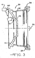
- Fig. 3 is a sectional view of a vehicle wheel and illustrates a process for finishing the vehicle wheel face in accordance with the invention.
- Fig. 4 is a plan view of a wheel surface finishing tool in accordance with the invention that is used in the finishing process illustrated in Fig. 3.
- Fig. 5 is a side elevation of the surface finishing tool shown in Fig. 4.
- Fig. 6 is an enlarged partial side elevation of the tool shown in Fig. 5.
- Fig. 7 is a flow chart for manufacturing a one piece vehicle wheel which utilizes the surface finishing process illustrated in Fig. 3.
- Fig. 8 is a flow chart for an alternate embodiment of the manufacturing process shown in Fig. 7.
- Fig. 9 is a flow chart for another alternate embodiment of the manufacturing process shown in Fig. 7.
- Fig. 10 is an alternate embodiment of the wheel surface finishing tool shown in Fig. 4.
- Fig. 11 is a side elevation of the surface finishing tool shown in Fig. 10.
- Fig. 3 a sectional view of a one piece wheel 30 having an outboard surface 31 and a process for finishing the wheel 30 in accordance with the present invention.
- the finishing involves cutting the wheel surface 31 with an improved cutting tool having a unique geometry that will be described below.
- An increased brightness or shine of the wheel surface is expected from the cutting process.
- the present invention is directed to smoothing the visible portions of a wheel face to cosmetically improve the appearance of the wheel face.
- the wheel 30 includes an annular wheel rim 32.
- a wheel disc 33 which includes the outboard surface 31 extends radially across the outboard end of the wheel rim 32.
- the invention contemplates mounting an inboard end of the wheel rim 32 in the jaws 34 of a lathe or a spinner chuck of a wheel lathe (not shown).
- the wheel 30 is rotated about an axis 35, as shown by the arrow in Fig. 3, by the wheel lathe.
- An improved cutting tool 40 is mounted upon a tool holder 41 that is secured to a wheel lathe turret (not shown).
- the wheel lathe urges the cutting tool 40 against the outboard wheel face 31 with uniform or equalized cutting pressure to simultaneously remove material from the wheel face 31 and smooth the cut surface.
- programmable machine tools are utilized to assure that the cutting pressure is equalized for all elevations of the geometric shape of the wheel being finished.
- the tool 40 is traversed in a radial direction from the outboard end of the wheel rim 32 across the wheel face 31.
- the tool 40 moves alternately toward and away from the center of the wheel disc 33, as shown by the small arrows in Fig. 3. As the tool 40 moves across the wheel face 31, the tool 40 also is moved axially to follow the contour of the wheel face 31.
- the invention further contemplates that the improved cutting tool 40 can be inclined to smooth all possible inclinations of the wheel face 31, such as horizontal, vertical or inclined, as illustrated in phantom in Fig. 3. Additionally, the tool 40 can be advanced in an axial, or radial, direction to increase the amount of material removed from the wheel face 31. Liquid coolant is applied to the working surface by a conventional supply means (not shown). As will be described below, a portion of the surface of the wheel face 31 is melted and then resolidified as the tool 40 passes thereover to form a smoothed portion of the wheel face 31.
- the improved cutting tool 40 is a specially modified face cutting tool.
- the tool 40 has a rhombic shaped body 42 having a bore 43 formed therethrough which receives a fastener (not shown) for securing the tool to the tool holder 41.
- the tool 40 is formed from a sintered carbide steel and includes an insert 44 insert attached to one end.
- the insert 44 is formed from a poly crystalline material which may be either naturally occurring or synthetically produced. In the preferred embodiment, the insert 44 is formed from a Poly Crystalline Diamond (PCD) material.
- the insert 44 includes an improved cutting tip 45 on one end that contacts the wheel face 31 and works the metal.
- the arrow in the upper left portion of Fig. 4 indicates the direction of movement of the worked metal relative to the cutting tool 40.
- the insert 44 has a length L of about six mm.
- the invention also contemplates applying a polycrystalline coating to a substrate to form the tool insert (not shown).
- a polycrystalline coating to form the tool insert (not shown).
- the inventors believe that either a diamond or ceramic coating may be utilized. The coating would be applied either before or after the geometry of the cutting tip is formed.
- the present invention contemplates a special geometry for the cutting tip 45.
- a standard cutting tip is outlined by the dashed line labeled 46 in Fig. 4. While the standard cutting tip 46 is symmetrical about the centerline of the tool, the cutting tip 45 of the improved tool 40 is non-symmetrical, having two different radii.
- the leading edge of the tip 45 has a larger radius R 1 while the trailing edge of the tip 45 has a smaller radius R 2 . Both radii R 1 and R 2 are perpendicular to the centerline of the tool 40. In the preferred embodiment, the leading edge radius R 1 is twice the trailing edge radius R 2 .
- leading edge radius R 1 is selected to be greater that the rate of feed per revolution programmed into the wheel lathe to cause multiple cutting of the wheel surface prior to the tangent point of the tip 45.
- leading edge radius R 1 is 3.01 mm while the trailing edge radius R 2 is 1.5 mm. These radii compare to a typical standard cutting tip radius of 1.0 mm. The direction of movement of the wheel being worked is indicated by the arrow in Fig. 4.
- the insert 44 is canted at an angle ⁇ relative to the top surface of the tool body 42.
- the angle ⁇ is seven degrees.
- a flat land 48 is formed around the upper edge of the insert 44.
- the land 48 is perpendicular, or has zero rake, to the top surface of the tool body 42. Because the insert 44 is canted relative to the tool body 42, the cutting edge of the insert 44 also forms an angle of ⁇ with the tool body top surface. Thus, the cutting edge of the insert 44 is maintained tangent to the surface of the face of the vehicle wheel.
- the land 48 has a width W that is in the range of between 0.076 and 0.254 mm with the preferred embodiment having a width in the range of 0.076 to 0.127 mm.
- the lower portion 49 of the insert 44 and the tool body 42 are undercut at an angle ⁇ to allow removal of the cut material.
- the angle ⁇ is in the range of five to 15 degrees and is five degrees in the preferred embodiment.
- the tool holder 41 is of conventional design but is formed of an anti-vibration material, such as, for example, machinable carbide to minimize vibration by avoiding resonance. Also, the tool holder 41 is designed for a minimum extension from the wheel lathe turret to increase the rigidity of the smear cutting tool 40. Additionally, it is contemplated that the associated wheel lathe includes a balanced chuck, centering, locating and clamping mechanisms.
- the zero rake land of the insert tip 44 rubs the wheel surface causing "work hardening" of the wheel metal.
- the present invention contemplates advancing the tool 40 in a "forward" direction.
- the unique geometry of the improved cutting tool tip 45 simultaneously removes material from the wheel face and smoothes the wheel face.
- the depth of material removed by the tool 40 is within the range of 0.05 mm to 0.1 mm. The friction between the tool tip 45 and the wheel surface generates sufficient heat to cause microscopic melting of the surface metal.
- the melted surface metal then resolidifies.
- the melting and resolidification of the metal can leave a bright surface that appears to have been polished.
- a layer of oxidized metal is formed upon the surface of the wheel.
- the oxidized layer is melted and quickly resolidifed during the cutting process with the improved cutting tool 40.
- an oxidized layer does not have a chance to be formed.
- a similar process is utilized to provide a lustrous surface finish to gold ingots.
- As a gold ingot solidifies the exterior surface becomes dull due to slight oxidation of the gold on the surface and impurities rising to the surface.
- a torch is used to heat and remelt the surface of the ingot to a semi-liquid state. The torch is quickly removed as soon as the ingot surface becomes shiny. This process for gold ingots is typically referred to as tinning.
- the inventors have found that if the feedrate for the improved tool 40 is one tenth or less than the leading edge radius R 1 , the surface appears to have been polished.
- the finishing process also seals any pores that could allow air to escape from a pneumatic tire mounted upon the wheel. Accordingly, the inventors expect that the number of "leakers" will be reduced.
- the invention further contemplates applying a layer of chrome plating 50 to the wheel disc face following the work hardening process.
- the layer of chrome plating 50 covers the smoothed portion of the wheel and provides an esthetically pleasing appearance.
- the inventors have found that the smoothing of the wheel surface described above eliminates the harmonically distorted pressures experienced with conventional polishing and buffing processes. Additionally, there is minimal wave effect in the wheel surface and the geometric edges of the wheel face are not rounded or softened by the abrasive effects of conventional polishing and buffing operations.
- use of the present invention results an a clarity of the surface of the aluminum chrome plated wheel that is at a level comparable to a surgical reflective mirror or a cosmetic mirror such as used in a compact or powder room.
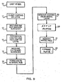
- the invention further contemplates a process for smoothing the wheel face that is illustrated by the flow chart shown in Fig. 7.
- Steps shown in Fig. 7 which are similar to steps shown in the flow charts in Figs. 1 and 2 and have the same numerical designators.
- a vehicle wheel is cast by a conventional casting process, such as, for example, gravity or low pressure casting, in functional block 10.
- functional blocks 11 through 15 the wheel casting is machined to a final shape as described above; however, a small amount of material is left for a final finishing cut with the special tool 40 described above.
- the outboard wheel face is smoothed on a wheel lathe or other conventional wheel finishing machine with a final finishing cut.
- the wheel is rotated upon the wheel lathe while a cutting tool having the unique geometry described above is urged against the outboard wheel face with a uniform cutting pressure while also being moved radially across the outboard wheel face.
- the depth of material removed by the tool 40 is within the range of 0.05 mm to 0.1 mm.
- the wheel surface is then finished with one or more chrome plated layers deposited by a conventional chrome plating process in functional block 25.
- the present invention contemplates that smoothing is included as one of the steps in the prior art process for machining a wheel casting.
- a cutting tool mounted upon a tool holder formed from an anti-vibration material can be added to the turret of the wheel lathe used to machine the wheel casting and the smoothing operation included as one of the programmed machining steps for finishing the wheel casting.
- a smoothing station which is dedicated to smoothing the wheel faces, can be established at the wheel manufacturing facility.
- the wheel is removed from the wheel lathe in functional block 52.
- An electrically non-conductive coating is applied to the non-smoothed portions of the wheel in functional block 54.
- the portions of the wheel surface that were smoothed in functional block 51 are masked before the coating is applied.
- the portions of the wheel surface adjacent to the windows formed between the wheel spokes may be coated while the remainder of the wheel face is chrome plated.
- the coating is a paint that includes pigment to add color to the coated area.
- the wheel surface can be covered with a clear coating or the coating may include both a layer of paint and a layer of clear coat that covers the paint.
- the coating may include an inert ingredient to further enhance the appearance of the wheel.
- the coating is sprayed onto the wheel surface and then cured. Once the coating has cured, the masking material is removed. Alternately, a spraying mask may be used to in place of masking material to control the application of the coating to the wheel surface.
- the wheel is chrome plated by a conventional process, such as by electrolysis with immersion in a tank. Upon immersion, the electrically non-conductive coating prevents adhesion of the chrome plating chemicals. Instead, the chrome plating chemicals only adhere to the bare metal portions of the wheel surface.
- FIG. 9 Another alternate manufacturing process is illustrated in Fig. 9, where, as before, blocks that are similar to blocks shown in preceding figures have the same numerical designators.
- the coating is applied to the wheel in functional block 54 before the portions of the wheel face are smoothed with the special tool 40 in functional block 54.
- the entire wheel face is coated in functional block 54.
- the tool 40 removes the coating from the portions of the face of the wheel to be chrome plated as it smoothes them.
- an electrically non-conductive material is sprayed onto the wheel face in functional block 54 and then cured.
- the coating material can be a paint that includes pigment, a clear coat or multiple layers of paint and clear coat. Additionally , an inert ingredient may be added to the coating material to further enhance the appearance of the wheel. Alternately, as described above, masking material or a spray mask can be used to restrict the coating material to only the portions of the wheel surface that are not to be chrome plated.
- masking material or a spray mask can be used to restrict the coating material to only the portions of the wheel surface that are not to be chrome plated.
- the invention also contemplates that the entire surface of wheel can be smoothed to provide an improvement in the cosmetic appearance to the wheel.
- the preferred embodiment has been described as being applied to cast wheels, it will be appreciated that the cosmetic appearance of wheels formed by other conventional processes also can be improved by application of the present invention.
- the present invention also contemplates smoothing the outboard surface of forged or stamped wheel discs.
- the preferred embodiment has been illustrated and described for aluminum or aluminum alloy wheels, it will be appreciated that the invention also may be practiced on wheels formed from other metals and alloys of other metals.
- a layer of clear coat may be optionally applied to the chrome plated surface (not shown).
- the inventors expect that using the improved cutting tool to cut and smooth the wheel face to enhance the cosmetic appearance thereof will cost less than buffing or polishing of the wheel face. Also, because the wheel can be smoothed on existing wheel lathes, no capital cost for polishing machines is required. The smoothing process eliminates both the exposure of personnel to toxic substances utilized during polishing and the expense of disposing of the toxic wastes generated thereby. Production time and cost will also be reduced since the need to ship the wheel to a polishing contractor will be eliminated.
- the improved cutting tool can extend into the wheel rim to reach the surface of a recessed wheel disc, which can be difficult to reach with polishing wheels. The cutting and smoothing preserves crisp edge surfaces which may be aesthetically desirable.
- the present invention results in a significantly improved surface appearance and a greatly enhanced appearance of any chrome plating applied over the smoothed surface.
- the invention also contemplates an alternate embodiment of the special smoothing tool 40 that is illustrated generally at 60 in Figs. 10 and 11.
- the tool 60 has a rhombic shaped body 42 having a bore 43 formed therethrough which receives a fastener (not shown) for securing the tool to the tool holder 41.
- the tool 40 is formed from a sintered carbide steel and includes an insert 64 attached to one end.
- the insert 64 is formed from a mono crystalline material which may be either naturally occurring or synthetically produced. In the preferred embodiment, the insert 64 is formed from a Single Crystalline Diamond (SCD) material.
- SCD Single Crystalline Diamond
- the insert 64 includes an improved cutting tip 65 on one end that contacts the wheel face 31 and works the metal.
- the arrow in the upper left portion of Fig. 10 indicates the direction of movement of the worked metal, or the wheel, relative to the smoothing tool 40.
- the insert 64 has a length L of about six mm.
- a mono crystalline insert 64 in place of the poly crystalline insert 44 described above significantly reduces the cost or the insert. Additionally, the use of a mono crystalline material allows a cutting tip 65 that is symmetrical about the centerline of the tool. In the preferred embodiment, the radius of the cutting tip, R, is formed in a ratio to the length of the tool 60 of about 1 to 16.
- the insert 64 is canted at an angle ⁇ relative to the top surface 66 of the tool body 42.
- the angle ⁇ is seven degrees.
- a flat land 68 is formed around the upper edge of the insert 64.
- the land 68 is perpendicular, or has zero rake, to the tool body top surface 66. Because the insert 64 is canted relative to the tool body 42, the cutting edge of the insert 64 also forms an angle of ⁇ with the tool body top surface. Thus, the cutting tip 65 of the insert 64 is maintained tangent to the surface of the face of the vehicle wheel.
- the land 68 has a width W that is in the range of between 0.076 and 0.254 mm with the preferred embodiment having a width in the range of 0.076 to 0.127 mm.
- the lower portion 69 of the insert 64 and the tool body 42 are undercut at an angle ⁇ to allow removal of the cut material.
- the angle ⁇ is in the range of five to 15 degrees and is five degrees in the preferred embodiment.
- the present invention contemplates that, in the preferred embodiment, the feed rate per revolution for a wheel lathe utilizing the tool 60 having the mono crystalline insert 64 is less that the cutting tip radius R.
- the invention also contemplates applying a poly or mono crystalline coating to a substrate to form the tool insert (not shown).
- a poly or mono crystalline coating may be utilized. The coating would be applied either before or after the geometry of the cutting tip is formed.
- the invention further contemplates applying a layer of clear coating over the entire outboard surface of the wheel to include the chrome plated portion (not shown); however, this step is optional.
Applications Claiming Priority (4)
| Application Number | Priority Date | Filing Date | Title |
|---|---|---|---|
| US44091403P | 2003-01-17 | 2003-01-17 | |
| US440914P | 2003-01-17 | ||
| US45001303P | 2003-02-26 | 2003-02-26 | |
| US450013P | 2003-02-26 |
Publications (2)
| Publication Number | Publication Date |
|---|---|
| EP1439018A1 true EP1439018A1 (fr) | 2004-07-21 |
| EP1439018B1 EP1439018B1 (fr) | 2015-06-03 |
Family
ID=32600296
Family Applications (1)
| Application Number | Title | Priority Date | Filing Date |
|---|---|---|---|
| EP04250222.9A Expired - Fee Related EP1439018B1 (fr) | 2003-01-17 | 2004-01-16 | Procédé de fabrication d'une surface décorative plaquée au chrome d'une roue |
Country Status (2)
| Country | Link |
|---|---|
| EP (1) | EP1439018B1 (fr) |
| JP (1) | JP4498754B2 (fr) |
Cited By (7)
| Publication number | Priority date | Publication date | Assignee | Title |
|---|---|---|---|---|
| EP2145708A3 (fr) * | 2008-07-16 | 2010-08-25 | Elatio Design Development GmbH | Procédé de fabrication d'une jante |
| CN102151843A (zh) * | 2011-02-22 | 2011-08-17 | 智奇铁路设备有限公司 | 一种高速动车组轮对的除漆工艺 |
| FR2983120A1 (fr) * | 2011-11-25 | 2013-05-31 | Peugeot Citroen Automobiles Sa | Procede de fabrication d'une roue comportant au moins une cuvette peinte |
| CN108759927A (zh) * | 2018-07-11 | 2018-11-06 | 江西新瑞泰零部件有限公司 | 一种具有提高镀铬表面检测效率的装置 |
| CN110835777A (zh) * | 2019-11-22 | 2020-02-25 | 王茜茜 | 一种金刚石齿轮加工用上砂装置 |
| CN111570827A (zh) * | 2020-05-09 | 2020-08-25 | 佛山镁利好自行车配件有限公司 | 一种自行车车轮中心轴孔加工专用刀具及加工方法 |
| US20230017058A1 (en) * | 2021-07-14 | 2023-01-19 | Howmet Aerospace Inc. | Vehicle wheels and methods of use |
Families Citing this family (2)
| Publication number | Priority date | Publication date | Assignee | Title |
|---|---|---|---|---|
| US6997787B2 (en) * | 2000-11-08 | 2006-02-14 | Hayes Lemmerz International, Inc. | Process for copper free chrome plating of a vehicle wheel surface |
| JP4523068B1 (ja) * | 2009-06-24 | 2010-08-11 | 有限会社村松研磨工業 | 2輪車用3ピース型アルミホイールのディスク |
Citations (12)
| Publication number | Priority date | Publication date | Assignee | Title |
|---|---|---|---|---|
| DE3118266A1 (de) * | 1981-05-08 | 1982-11-25 | Günter 7022 Leinfelden-Echterdingen Schwarz | "verfahren zum herstellen einer felge fuer fahrzeugraeder, insbesondere kraftfahrzeugraeder und nach dem verfahren hergestellte felge" |
| US4929315A (en) * | 1986-10-31 | 1990-05-29 | Audi Ag | Method for electroplating a conducting surface |
| US5099558A (en) * | 1988-04-25 | 1992-03-31 | The B. F. Goodrich Company | Burnishing tool holder |
| JPH08118104A (ja) * | 1994-10-24 | 1996-05-14 | Enkei Automot Kk | バイト |
| US5728426A (en) * | 1995-04-18 | 1998-03-17 | Hayes Wheels International, Inc. | Method of manufacturing a plated vehicle wheel having non-plated tire bead seats |
| US5803553A (en) * | 1995-12-08 | 1998-09-08 | Hayes Lemmerz International, Inc. | Two piece vehicle wheel with mechanically locked sections |
| WO1998041360A1 (fr) * | 1997-03-19 | 1998-09-24 | Hayes Wheels International, Inc. | Roue de vehicule polie |
| GB2339713A (en) * | 1998-07-23 | 2000-02-09 | Valenite Inc | A cutting insert |
| JP2000127702A (ja) * | 1998-10-30 | 2000-05-09 | Topy Ind Ltd | 大中型メッキホイールおよびその製造方法 |
| DE10034228A1 (de) * | 1999-07-16 | 2001-02-15 | Aisin Aw Co | Schneidspitze, Schneidverfahren und durch Schneiden bearbeitetes Element |
| WO2001032339A1 (fr) * | 1999-11-01 | 2001-05-10 | Kosei Aluminum Co., Ltd. | Finissage de surface miroir |
| EP1211025A2 (fr) * | 2000-11-29 | 2002-06-05 | Hayes Lemmerz International, Inc. | Outil et procédé de finissage de la surface des roues de véhicule |
Family Cites Families (6)
| Publication number | Priority date | Publication date | Assignee | Title |
|---|---|---|---|---|
| JPS63105999A (ja) * | 1986-10-21 | 1988-05-11 | Nippon Light Metal Co Ltd | アルミニウムホイ−ルの部分的光輝処理方法 |
| JPH06293974A (ja) * | 1993-04-06 | 1994-10-21 | Hitachi Metals Ltd | アルミホイールの表面処理方法 |
| JPH07329502A (ja) * | 1994-06-13 | 1995-12-19 | Nissan Motor Co Ltd | 光輝アルミロードホイールの製造方法 |
| JPH10130822A (ja) * | 1996-10-28 | 1998-05-19 | Totsuka Sogyo:Kk | 金属表面処理方法 |
| JP4785225B2 (ja) * | 2000-04-11 | 2011-10-05 | トピー工業株式会社 | 自動車用アルミ合金ホイール塗装の前処理方法 |
| JP2002088492A (ja) * | 2000-06-30 | 2002-03-27 | Topy Ind Ltd | アルミホイールの塗装方法 |
-
2004
- 2004-01-16 EP EP04250222.9A patent/EP1439018B1/fr not_active Expired - Fee Related
- 2004-01-19 JP JP2004010492A patent/JP4498754B2/ja not_active Expired - Fee Related
Patent Citations (12)
| Publication number | Priority date | Publication date | Assignee | Title |
|---|---|---|---|---|
| DE3118266A1 (de) * | 1981-05-08 | 1982-11-25 | Günter 7022 Leinfelden-Echterdingen Schwarz | "verfahren zum herstellen einer felge fuer fahrzeugraeder, insbesondere kraftfahrzeugraeder und nach dem verfahren hergestellte felge" |
| US4929315A (en) * | 1986-10-31 | 1990-05-29 | Audi Ag | Method for electroplating a conducting surface |
| US5099558A (en) * | 1988-04-25 | 1992-03-31 | The B. F. Goodrich Company | Burnishing tool holder |
| JPH08118104A (ja) * | 1994-10-24 | 1996-05-14 | Enkei Automot Kk | バイト |
| US5728426A (en) * | 1995-04-18 | 1998-03-17 | Hayes Wheels International, Inc. | Method of manufacturing a plated vehicle wheel having non-plated tire bead seats |
| US5803553A (en) * | 1995-12-08 | 1998-09-08 | Hayes Lemmerz International, Inc. | Two piece vehicle wheel with mechanically locked sections |
| WO1998041360A1 (fr) * | 1997-03-19 | 1998-09-24 | Hayes Wheels International, Inc. | Roue de vehicule polie |
| GB2339713A (en) * | 1998-07-23 | 2000-02-09 | Valenite Inc | A cutting insert |
| JP2000127702A (ja) * | 1998-10-30 | 2000-05-09 | Topy Ind Ltd | 大中型メッキホイールおよびその製造方法 |
| DE10034228A1 (de) * | 1999-07-16 | 2001-02-15 | Aisin Aw Co | Schneidspitze, Schneidverfahren und durch Schneiden bearbeitetes Element |
| WO2001032339A1 (fr) * | 1999-11-01 | 2001-05-10 | Kosei Aluminum Co., Ltd. | Finissage de surface miroir |
| EP1211025A2 (fr) * | 2000-11-29 | 2002-06-05 | Hayes Lemmerz International, Inc. | Outil et procédé de finissage de la surface des roues de véhicule |
Non-Patent Citations (2)
| Title |
|---|
| PATENT ABSTRACTS OF JAPAN vol. 1996, no. 09 30 September 1996 (1996-09-30) * |
| PATENT ABSTRACTS OF JAPAN vol. 2000, no. 08 6 October 2000 (2000-10-06) * |
Cited By (9)
| Publication number | Priority date | Publication date | Assignee | Title |
|---|---|---|---|---|
| EP2145708A3 (fr) * | 2008-07-16 | 2010-08-25 | Elatio Design Development GmbH | Procédé de fabrication d'une jante |
| CN102151843A (zh) * | 2011-02-22 | 2011-08-17 | 智奇铁路设备有限公司 | 一种高速动车组轮对的除漆工艺 |
| CN102151843B (zh) * | 2011-02-22 | 2012-11-07 | 智奇铁路设备有限公司 | 一种高速动车组轮对的除漆工艺 |
| FR2983120A1 (fr) * | 2011-11-25 | 2013-05-31 | Peugeot Citroen Automobiles Sa | Procede de fabrication d'une roue comportant au moins une cuvette peinte |
| CN108759927A (zh) * | 2018-07-11 | 2018-11-06 | 江西新瑞泰零部件有限公司 | 一种具有提高镀铬表面检测效率的装置 |
| CN108759927B (zh) * | 2018-07-11 | 2024-01-30 | 江西新瑞泰零部件有限公司 | 一种具有提高镀铬表面检测效率的装置 |
| CN110835777A (zh) * | 2019-11-22 | 2020-02-25 | 王茜茜 | 一种金刚石齿轮加工用上砂装置 |
| CN111570827A (zh) * | 2020-05-09 | 2020-08-25 | 佛山镁利好自行车配件有限公司 | 一种自行车车轮中心轴孔加工专用刀具及加工方法 |
| US20230017058A1 (en) * | 2021-07-14 | 2023-01-19 | Howmet Aerospace Inc. | Vehicle wheels and methods of use |
Also Published As
| Publication number | Publication date |
|---|---|
| EP1439018B1 (fr) | 2015-06-03 |
| JP4498754B2 (ja) | 2010-07-07 |
| JP2004224338A (ja) | 2004-08-12 |
Similar Documents
| Publication | Publication Date | Title |
|---|---|---|
| US7140949B2 (en) | Tool and process for chrome plating a vehicle wheel surface | |
| US6540450B2 (en) | Tool and process for finishing a vehicle wheel surface | |
| JP2006143205A (ja) | 車両ホイール表面へ銅フリークロムめっきを施す方法 | |
| EP1627706B1 (fr) | Outil abrasif, méthode de sa production / restauration et procédé de meulage par point | |
| US7896728B2 (en) | Machining methods using superabrasive tool | |
| JP4516509B2 (ja) | 車両ホイールの製造方法 | |
| EP1439018B1 (fr) | Procédé de fabrication d'une surface décorative plaquée au chrome d'une roue | |
| US6926593B1 (en) | Vehicle wheel hole deburring device and method | |
| JPH07223126A (ja) | アルミホイールの表面処理方法 | |
| EP1118430B1 (fr) | Machine de rectification et procédé d'usinage | |
| WO1998003281A1 (fr) | Procede de formation par torsion d'une roue de vehicule | |
| WO1998041360A9 (fr) | Roue de vehicule polie | |
| WO1998041360A1 (fr) | Roue de vehicule polie | |
| JP7040804B2 (ja) | 車両用ホイールの製造方法及び車両用ホイール | |
| KR20070018609A (ko) | 단조 또는 스피닝법으로 제조된 알루미늄휠의 장식방법과이에 의해 제조되는 자동차용 알루미늄 휠 | |
| US20030096142A1 (en) | Dual coated cubic boron nitride cutting tool and method of employing same | |
| JPH04223820A (ja) | 砥粒リーマ | |
| JPH06231B2 (ja) | 軽合金製ホイールの塗装方法 | |
| JP3233284B2 (ja) | アルミニウム合金製車両用ホイールの製造方法 | |
| US20190076911A1 (en) | Method for coating and forging vehicle wheel | |
| Fischer | Hard coatings on contaminated surfaces--a case study |
Legal Events
| Date | Code | Title | Description |
|---|---|---|---|
| PUAI | Public reference made under article 153(3) epc to a published international application that has entered the european phase |
Free format text: ORIGINAL CODE: 0009012 |
|
| AK | Designated contracting states |
Kind code of ref document: A1 Designated state(s): AT BE BG CH CY CZ DE DK EE ES FI FR GB GR HU IE IT LI LU MC NL PT RO SE SI SK TR |
|
| AX | Request for extension of the european patent |
Extension state: AL LT LV MK |
|
| 17P | Request for examination filed |
Effective date: 20050119 |
|
| AKX | Designation fees paid |
Designated state(s): DE GB |
|
| 17Q | First examination report despatched |
Effective date: 20080229 |
|
| REG | Reference to a national code |
Ref country code: DE Ref legal event code: R079 Ref document number: 602004047288 Country of ref document: DE Free format text: PREVIOUS MAIN CLASS: B23B0027140000 Ipc: B23B0005020000 |
|
| GRAP | Despatch of communication of intention to grant a patent |
Free format text: ORIGINAL CODE: EPIDOSNIGR1 |
|
| RAP1 | Party data changed (applicant data changed or rights of an application transferred) |
Owner name: HAYES LEMMERZ INTERNATIONAL, INC. |
|
| RIC1 | Information provided on ipc code assigned before grant |
Ipc: B23B 5/02 20060101AFI20150217BHEP Ipc: C25D 5/44 20060101ALI20150217BHEP Ipc: B23B 27/14 20060101ALI20150217BHEP Ipc: C25D 7/00 20060101ALI20150217BHEP Ipc: C25D 11/38 20060101ALI20150217BHEP Ipc: B60B 3/02 20060101ALI20150217BHEP Ipc: C25D 5/02 20060101ALI20150217BHEP |
|
| INTG | Intention to grant announced |
Effective date: 20150303 |
|
| GRAS | Grant fee paid |
Free format text: ORIGINAL CODE: EPIDOSNIGR3 |
|
| GRAA | (expected) grant |
Free format text: ORIGINAL CODE: 0009210 |
|
| AK | Designated contracting states |
Kind code of ref document: B1 Designated state(s): DE GB |
|
| REG | Reference to a national code |
Ref country code: GB Ref legal event code: FG4D |
|
| REG | Reference to a national code |
Ref country code: DE Ref legal event code: R096 Ref document number: 602004047288 Country of ref document: DE |
|
| REG | Reference to a national code |
Ref country code: DE Ref legal event code: R097 Ref document number: 602004047288 Country of ref document: DE |
|
| PLBE | No opposition filed within time limit |
Free format text: ORIGINAL CODE: 0009261 |
|
| STAA | Information on the status of an ep patent application or granted ep patent |
Free format text: STATUS: NO OPPOSITION FILED WITHIN TIME LIMIT |
|
| 26N | No opposition filed |
Effective date: 20160304 |
|
| REG | Reference to a national code |
Ref country code: DE Ref legal event code: R119 Ref document number: 602004047288 Country of ref document: DE |
|
| GBPC | Gb: european patent ceased through non-payment of renewal fee |
Effective date: 20160116 |
|
| PG25 | Lapsed in a contracting state [announced via postgrant information from national office to epo] |
Ref country code: DE Free format text: LAPSE BECAUSE OF NON-PAYMENT OF DUE FEES Effective date: 20160802 Ref country code: GB Free format text: LAPSE BECAUSE OF NON-PAYMENT OF DUE FEES Effective date: 20160116 |