EP1439016A1 - Tube de coulée, dispositif de clamage d'un tube de coulée et installation de coulée - Google Patents
Tube de coulée, dispositif de clamage d'un tube de coulée et installation de coulée Download PDFInfo
- Publication number
- EP1439016A1 EP1439016A1 EP03447014A EP03447014A EP1439016A1 EP 1439016 A1 EP1439016 A1 EP 1439016A1 EP 03447014 A EP03447014 A EP 03447014A EP 03447014 A EP03447014 A EP 03447014A EP 1439016 A1 EP1439016 A1 EP 1439016A1
- Authority
- EP
- European Patent Office
- Prior art keywords
- tube
- pouring
- plate
- angle
- casting
- Prior art date
- Legal status (The legal status is an assumption and is not a legal conclusion. Google has not performed a legal analysis and makes no representation as to the accuracy of the status listed.)
- Withdrawn
Links
- 238000005266 casting Methods 0.000 title claims description 24
- 238000011144 upstream manufacturing Methods 0.000 claims description 12
- 238000009434 installation Methods 0.000 claims description 3
- 230000007246 mechanism Effects 0.000 claims description 3
- 230000008859 change Effects 0.000 claims description 2
- 230000035882 stress Effects 0.000 description 11
- 238000005336 cracking Methods 0.000 description 7
- 239000000463 material Substances 0.000 description 5
- 239000002184 metal Substances 0.000 description 5
- 239000011819 refractory material Substances 0.000 description 5
- 238000005452 bending Methods 0.000 description 4
- 230000015572 biosynthetic process Effects 0.000 description 4
- QVGXLLKOCUKJST-UHFFFAOYSA-N atomic oxygen Chemical compound [O] QVGXLLKOCUKJST-UHFFFAOYSA-N 0.000 description 3
- 229910001338 liquidmetal Inorganic materials 0.000 description 3
- 239000001301 oxygen Substances 0.000 description 3
- 229910052760 oxygen Inorganic materials 0.000 description 3
- IJGRMHOSHXDMSA-UHFFFAOYSA-N Atomic nitrogen Chemical compound N#N IJGRMHOSHXDMSA-UHFFFAOYSA-N 0.000 description 2
- 229910000831 Steel Inorganic materials 0.000 description 2
- 230000006866 deterioration Effects 0.000 description 2
- 230000003628 erosive effect Effects 0.000 description 2
- 230000002349 favourable effect Effects 0.000 description 2
- 239000007788 liquid Substances 0.000 description 2
- 238000000034 method Methods 0.000 description 2
- 238000007789 sealing Methods 0.000 description 2
- 239000010959 steel Substances 0.000 description 2
- 230000000930 thermomechanical effect Effects 0.000 description 2
- 230000009471 action Effects 0.000 description 1
- 239000012080 ambient air Substances 0.000 description 1
- 230000006835 compression Effects 0.000 description 1
- 238000007906 compression Methods 0.000 description 1
- 238000011109 contamination Methods 0.000 description 1
- 230000007797 corrosion Effects 0.000 description 1
- 238000005260 corrosion Methods 0.000 description 1
- 238000013016 damping Methods 0.000 description 1
- 230000002950 deficient Effects 0.000 description 1
- 238000007865 diluting Methods 0.000 description 1
- 230000006872 improvement Effects 0.000 description 1
- 238000004519 manufacturing process Methods 0.000 description 1
- 230000005499 meniscus Effects 0.000 description 1
- 229910052757 nitrogen Inorganic materials 0.000 description 1
- 230000009467 reduction Effects 0.000 description 1
- 230000001105 regulatory effect Effects 0.000 description 1
- 239000007787 solid Substances 0.000 description 1
- 239000000126 substance Substances 0.000 description 1
- 230000008646 thermal stress Effects 0.000 description 1
Images

Classifications
-
- B—PERFORMING OPERATIONS; TRANSPORTING
- B22—CASTING; POWDER METALLURGY
- B22D—CASTING OF METALS; CASTING OF OTHER SUBSTANCES BY THE SAME PROCESSES OR DEVICES
- B22D41/00—Casting melt-holding vessels, e.g. ladles, tundishes, cups or the like
- B22D41/14—Closures
- B22D41/22—Closures sliding-gate type, i.e. having a fixed plate and a movable plate in sliding contact with each other for selective registry of their openings
- B22D41/28—Plates therefor
-
- B—PERFORMING OPERATIONS; TRANSPORTING
- B22—CASTING; POWDER METALLURGY
- B22D—CASTING OF METALS; CASTING OF OTHER SUBSTANCES BY THE SAME PROCESSES OR DEVICES
- B22D41/00—Casting melt-holding vessels, e.g. ladles, tundishes, cups or the like
- B22D41/50—Pouring-nozzles
-
- B—PERFORMING OPERATIONS; TRANSPORTING
- B22—CASTING; POWDER METALLURGY
- B22D—CASTING OF METALS; CASTING OF OTHER SUBSTANCES BY THE SAME PROCESSES OR DEVICES
- B22D41/00—Casting melt-holding vessels, e.g. ladles, tundishes, cups or the like
- B22D41/50—Pouring-nozzles
- B22D41/56—Means for supporting, manipulating or changing a pouring-nozzle
Definitions
- the present invention relates to a pouring tube for the conduct of a liquid metal from an upper metallurgical vessel to a lower metallurgical vessel.
- it concerns a pouring tube of refractory material for the transfer of liquid steel from a distributor to an ingot mold or, alternatively, from a ladle to a distributor.
- one generally uses a pouring tube made up of a part tubular delimiting a pouring channel and, at its upper end, a plate provided with a orifice delimiting a pouring channel, said plate comprising an upper face ensuring the contact with the upstream part of the casting channel and a lower face forming the interface with the lower part of the tube, said lower face comprising two flat bearing faces located on either side of the sprue.
- the tube is intended to slide in guides against the flat underside of either pouring orifice such as an internal nozzle, or of a fixed bottom plate attached to such an orifice of casting, either of a fixed plate attached to a mechanism for regulating the inserted casting jet between the pouring hole (internal nozzle for example) and the pouring tube. It is quite clear that in the context of the present invention, when referring to a pouring tube, it is indeed this tube intended to slide in a device and not of a fixed tube like an internal nozzle.
- Known devices and in particular that described in document EP 192,019 provide that the pouring tube is slidably mounted on guides capable of transmitting a thrust force to the top.
- This thrust force is obtained by springs mounted at a respectable distance of the pouring orifice and acting on levers or rockers. These transmit force thrust on the flat bearing faces of the plate of the pouring tube. This push up relatively tightly applies the plate of the pouring tube against the refractory piece upstream including an internal nozzle or a refractory plate.
- the pouring tubes can be made in one piece or can be constituted by a assembly of several refractory parts.
- Document EP 1,133,373 for its part, describes a tube comprising an interface zone damping between the metal casing and the refractory tube.
- This area has a material whose thermal properties are such that it remains solid at ambient temperatures but undergoes deformations at high temperatures.
- This buffer zone reduces the risk of formation cracks or microcracks generated by thermo-mechanical stresses appearing during start of casting.
- the plate undergoes always, perpendicular to its surface, significant bending stresses which can be responsible for the formation of cracks at the upper end of the tubular part.
- the upper plate can be deformed by bending around an axis parallel to the direction of the guides in which said plate slides.
- the present invention relates to a pouring tube whose shape is adapted in order to better resist the constraints imposed during its use and in particular the constraints linked maintaining the tube in the device.
- the tube also has a shape adapted to receive a clamping system which generates a favorable stress profile.
- the subject of the present invention is a pouring tube for a supply device. and for exchanging a tube consisting of a tubular part delimiting a pouring channel and, at its upper end, of a plate, provided with an orifice delimiting a pouring channel, said plate comprising an upper face ensuring contact with the upstream part of the pouring channel and a lower face forming the interface with the tubular part of the tube; said plate comprising two flat support faces located on the side opposite to the upper face of the plate and located on either side across the runner.
- This tube is characterized in that said two faces form with the axis of the runner an angle ⁇ from 20 ° to 80 °.
- the tubular part can be of general shape cylindrical, oval or conical.
- the plate is preferably of square or rectangular shape.
- the shape of the plate according to the invention makes it possible to improve the resistance to cracking and without increasing the amount of material in the crack-sensitive area.
- the dimensions dimensions remain in fact substantially identical to those of the tubes of the prior art.
- the plate of the tube is asymmetrical by relative to the plane perpendicular to the bearing faces of the tube plate and comprising the axis of the pouring channel. Consequently, the useful surface of the plate on either side of this plane is different.
- This allows a tube to be brought into two positions, a pouring position in which the orifice the plate corresponds to the upstream casting channel and an intermediate position where the orifice of the plate does not communicate with the upstream pouring channel in order to obstruct it.
- This turns out useful when the upstream closing system provided for example by the stopper rod is defective. It also makes it possible to no longer use a safety plate since the closure can be ensured by the tube plate itself.
- the shape of the tube according to the invention also allows the use of a clamping device different from those used in the prior art.
- the present invention therefore also relates to a device for clamping a tube of casting for a device for supplying and exchanging a tube.
- the clamping device according to the invention is characterized in that the resulting pushing force is applied in a direction forming an angle ⁇ of 10 ° to 70 ° with the axis of the pouring channel.
- the clamping device exerts on the bearing faces of the plate of the pouring tube a pushing force, not directed upwards parallel to the casting axis as in existing devices, but oblique to it and directed towards the pouring channel.
- the bending stresses in the pouring tube generated by such a device claims are lower than those of the prior art devices.
- the resulting force of thrust has a vertical component which ensures contact and sealing with the part upstream and a horizontal component.
- This horizontal component is favorable since it puts the refractory material in compression which makes it possible to reduce the appearance of cracks and / or limit their spread.
- the resulting pushing force of the clamping device according to the invention must be applied with an angle ⁇ from 10 ° to 70 °. Indeed, an angle less than 10 ° amounts to applying a quasi-vertical force as in the known devices and has no significant positive influence on the phenomenon of cracking. When the force is applied at an angle greater than 70 °, the vertical component of the force is no longer sufficient to ensure good contact and good sealing between the pouring tube plate and the upstream part.
- a thrust angle ⁇ from 30 ° to 60 °, and in particular a close angle of 45 ° gives good results with regard to the resistance to cracking and the profile of constraints.
- the tensile stresses measured in a pouring tube at the level of the area critical for a 45 ° thrust angle are 40 to 50% lower than those measured for a thrust angle of 90 ° corresponding to the state of the art.
- a 45 ° angle is a good compromise between the vertical component of the thrust force which seals between the tube and the upstream part and the horizontal component of the force. Indeed a vertical component minimum is necessary to allow tight contact between the tube and the upstream part. More the angle ⁇ increases and greater must be the pushing force to ensure the same vertical component. Too high a push force causes mechanical problems non-negligible, in particular increased stress on the springs and a reduction in their duration of life.
- An angle of 45 ° also allows easy production of the pouring tube and the device of clamor.
- the pushing force can be applied directly to the bearing face of the plate of the pouring tube, for example by means of springs or by means of an element such as rocker.
- Another aspect of the invention is a casting installation comprising a mechanism tube supply and exchange, comprising a pouring tube according to the invention and a device for clamage according to the invention.
- the pouring tube is kept in tight contact with the upstream casting part at the by means of the clamping device.
- the pushing force of the clamping device being applied to the two flat bearing faces of the plate of the pouring tube.
- the casting installation includes also a guide rail system adapted to receive the two bearing faces of the tube pouring and allowing to bring a new pouring tube in the pouring position and to drive out the used pouring tube outside the pouring position.
- the slide system has a bearing surface whose angle forms with the axis of casting an angle substantially equal to the angle ⁇ formed by the bearing faces of the tube plate casting with said casting axis.
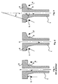
- FIG. 1 a pouring tube according to the state of the art and the resulting force of vertical thrust applied to the flat bearing faces.
- FIG. 2 represents a pouring tube according to the invention and the resulting pushing force applied to the flat bearing faces.
- FIG. 3 represents a pouring tube according to the invention, the angles ⁇ and ⁇ respectively represent the angle formed by the resulting pushing force with the axis of the pouring channel and the angle formed by the planar bearing face with the axis of the sprue.
- FIG. 4 represents a clamping device according to the state of the art.
- FIG. 5 represents an embodiment of a clamping device according to the invention.
- FIG. 1 represents a pouring tube (1) of the state of the art comprising a plate (2) and a tubular part (3).
- the flat bearing faces (5) form an angle ⁇ of 90 ° with the axis of the pouring channel (7).
- the pushing force (4) is vertical, parallel to the axis of the casting (7).
- the stresses generated in the pouring tube (4) of the prior art can be responsible for the formation of cracks at the upper end of the tubular part (3).
- FIGS 2 and 3 show a pouring tube (1) according to the invention.
- the plate (2) of pouring tube (1) is somewhat truncated.
- the flat bearing faces (5) form a angle ⁇ from 20 ° to 80 ° and this, without requiring an increase in the amount of material of the plate (2).
- Figure 3 shows the angles ⁇ and ⁇ .
- the resulting pushing force and the axis of the channel of casting form an angle ⁇ of 21 °.
- the flat bearing faces and the axis of the pouring channel form an angle ⁇ of 69 °.
- Figure 4 shows a clamping device (8) of the prior art. Strength resulting from thrust (4) is applied vertically, parallel to the casting axis (7), by through a rocker arm (10).
- FIG. 5 represents a clamping device (8) according to the invention.
- the resulting force of thrust (4) is applied via a rocker arm (10).
- Figure 6 shows a clamping device (8) according to the invention.
- the resulting force of thrust (4) is applied directly to the bearing faces thanks to the springs (11).
Landscapes
- Engineering & Computer Science (AREA)
- Mechanical Engineering (AREA)
- Casting Support Devices, Ladles, And Melt Control Thereby (AREA)
- Continuous Casting (AREA)
- Reciprocating Pumps (AREA)
- Re-Forming, After-Treatment, Cutting And Transporting Of Glass Products (AREA)
- Casting Or Compression Moulding Of Plastics Or The Like (AREA)
Priority Applications (27)
| Application Number | Priority Date | Filing Date | Title |
|---|---|---|---|
| EP03447014A EP1439016A1 (fr) | 2003-01-20 | 2003-01-20 | Tube de coulée, dispositif de clamage d'un tube de coulée et installation de coulée |
| ARP040100100A AR042883A1 (es) | 2003-01-20 | 2004-01-15 | Tubo de colada, dispositivo de empuje de un tubo de colada e instalacion de colada |
| TW093101167A TWI307645B (en) | 2003-01-20 | 2004-01-16 | Casting nozzle, clamping device for a casting nozzle and casting installation |
| CL200400059A CL43158B (es) | 2003-01-20 | 2004-01-16 | Tubo de colada para conduccion de metal liquido constituido por una parte tubular que delimita un canal, una placa provista de un orificio, conteniendo dos caras una superior y una inferior dichas caras de apoyo forman con el eje del canal de colada |
| KR1020057013319A KR101061405B1 (ko) | 2003-01-20 | 2004-01-19 | 주입 노즐과, 이 주입 노즐의 압박 장치와, 주조 설비 |
| CA2513116A CA2513116C (en) | 2003-01-20 | 2004-01-19 | Pouring nozzle, pushing device for a pouring nozzle and casting installation |
| ES04703122T ES2262112T5 (es) | 2003-01-20 | 2004-01-19 | Tubo de colada, dispositivo de empuje de un tubo de colada e instalación de colada. |
| MXPA05007688A MXPA05007688A (es) | 2003-01-20 | 2004-01-19 | Tubo de colada, dispositivo de empuje en un tubo de colada e instalacion de colada. |
| UAA200508057A UA79533C2 (en) | 2003-01-20 | 2004-01-19 | Pouring nozzle, pushing device for pouring nozzle and casting installation |
| ZA200505390A ZA200505390B (en) | 2003-01-20 | 2004-01-19 | Pouring nozzle, pushing device for a pouring nozzle and casting installation |
| SI200430025T SI1590114T2 (sl) | 2003-01-20 | 2004-01-19 | Vlivni nastavek za vlivanje, pritisna naprava za vlivni nastavek za vlivanje in napeljava za vlivanje |
| EP04703122A EP1590114B2 (en) | 2003-01-20 | 2004-01-19 | Pouring nozzle, pushing device for a pouring nozzle and casting installation |
| AT04703122T ATE320873T1 (de) | 2003-01-20 | 2004-01-19 | Giessdüse, drückvorrichtung für eine giessdüse und giessanlage |
| JP2006500421A JP2006515803A (ja) | 2003-01-20 | 2004-01-19 | 注入ノズル、注入ノズルの押し付け装置及び鋳造装置 |
| PCT/BE2004/000010 WO2004065041A1 (en) | 2003-01-20 | 2004-01-19 | Pouring nozzle, pushing device for a pouring nozzle and casting installation |
| PT04703122T PT1590114E (pt) | 2003-01-20 | 2004-01-19 | Bocal de vazamento, dispositivo de impulsao para um bocal de vazamento e instalacao de fundicao |
| EA200501021A EA006691B1 (ru) | 2003-01-20 | 2004-01-19 | Разливочный стакан, устройство для его введения и/или удаления и установка для разливки металла |
| US10/542,698 US8127972B2 (en) | 2003-01-20 | 2004-01-19 | Pouring nozzle, pushing device for a pouring nozzle and casting installation |
| DE602004000532T DE602004000532T3 (de) | 2003-01-20 | 2004-01-19 | Giessdüse, drückvorrichtung für eine giessdüse und giessanlage |
| AU2004205428A AU2004205428B2 (en) | 2003-01-20 | 2004-01-19 | Pouring nozzle, pushing device for a pouring nozzle and casting installation |
| PL378020A PL207935B1 (pl) | 2003-01-20 | 2004-01-19 | Urządzenie odlewnicze, wylew kadziowy oraz urządzenie do wprowadzania i/lub wyjmowania wylewu kadziowego |
| CNB2004800000449A CN1325208C (zh) | 2003-01-20 | 2004-01-19 | 浇注嘴、适用于该浇注嘴的推压装置、和铸造设备 |
| BRPI0406798-3A BRPI0406798B1 (pt) | 2003-01-20 | 2004-01-19 | Bocal de vazamento, dispositivo de inserção e/ou remoção para um bocal de vazamento e instalação de lingotamento |
| EGNA2005000401 EG23879A (en) | 2003-01-20 | 2005-07-20 | Pouring nozzle, pushing device for a pouring nozzle and casting installation |
| MA28437A MA27620A1 (fr) | 2003-01-20 | 2005-08-12 | Buse de coulee, dispositif de poussee pour la buse de coulee, et installation de coulee |
| JP2011058475A JP2011115859A (ja) | 2003-01-20 | 2011-03-16 | 注入ノズル、注入ノズルの押し付け装置及び鋳造装置 |
| JP2013233449A JP5926230B2 (ja) | 2003-01-20 | 2013-11-11 | 注入ノズル、注入ノズルの押し付け装置及び鋳造装置 |
Applications Claiming Priority (1)
| Application Number | Priority Date | Filing Date | Title |
|---|---|---|---|
| EP03447014A EP1439016A1 (fr) | 2003-01-20 | 2003-01-20 | Tube de coulée, dispositif de clamage d'un tube de coulée et installation de coulée |
Publications (1)
| Publication Number | Publication Date |
|---|---|
| EP1439016A1 true EP1439016A1 (fr) | 2004-07-21 |
Family
ID=32524313
Family Applications (2)
| Application Number | Title | Priority Date | Filing Date |
|---|---|---|---|
| EP03447014A Withdrawn EP1439016A1 (fr) | 2003-01-20 | 2003-01-20 | Tube de coulée, dispositif de clamage d'un tube de coulée et installation de coulée |
| EP04703122A Expired - Lifetime EP1590114B2 (en) | 2003-01-20 | 2004-01-19 | Pouring nozzle, pushing device for a pouring nozzle and casting installation |
Family Applications After (1)
| Application Number | Title | Priority Date | Filing Date |
|---|---|---|---|
| EP04703122A Expired - Lifetime EP1590114B2 (en) | 2003-01-20 | 2004-01-19 | Pouring nozzle, pushing device for a pouring nozzle and casting installation |
Country Status (24)
| Country | Link |
|---|---|
| US (1) | US8127972B2 (https=) |
| EP (2) | EP1439016A1 (https=) |
| JP (3) | JP2006515803A (https=) |
| KR (1) | KR101061405B1 (https=) |
| CN (1) | CN1325208C (https=) |
| AR (1) | AR042883A1 (https=) |
| AT (1) | ATE320873T1 (https=) |
| AU (1) | AU2004205428B2 (https=) |
| BR (1) | BRPI0406798B1 (https=) |
| CA (1) | CA2513116C (https=) |
| CL (1) | CL43158B (https=) |
| DE (1) | DE602004000532T3 (https=) |
| EA (1) | EA006691B1 (https=) |
| EG (1) | EG23879A (https=) |
| ES (1) | ES2262112T5 (https=) |
| MA (1) | MA27620A1 (https=) |
| MX (1) | MXPA05007688A (https=) |
| PL (1) | PL207935B1 (https=) |
| PT (1) | PT1590114E (https=) |
| SI (1) | SI1590114T2 (https=) |
| TW (1) | TWI307645B (https=) |
| UA (1) | UA79533C2 (https=) |
| WO (1) | WO2004065041A1 (https=) |
| ZA (1) | ZA200505390B (https=) |
Cited By (6)
| Publication number | Priority date | Publication date | Assignee | Title |
|---|---|---|---|---|
| WO2011113596A1 (en) * | 2010-03-19 | 2011-09-22 | Vesuvius Group S.A. | Device for holding and replacing a casting plate in a casting installation, metallic casing of casting plate and casting plate, provided with means interacting with a device detector |
| EP2368654A1 (fr) * | 2010-03-19 | 2011-09-28 | Vesuvius Group S.A | Dispositif de maintien et de changement d'une plaque de coulée dans une installation de coulée, enveloppe métallique de plaque de coulée et plaque de coulée, munies de moyens coopérant avec un détecteur du dispositif. |
| EP2386368A1 (fr) * | 2010-03-19 | 2011-11-16 | Vesuvius Group S.A | Busette interne pour le transfert de métal liquide contenu dans un récipient, système de clamage de cette busette et dispositif de coulée |
| CN103180068A (zh) * | 2010-10-20 | 2013-06-26 | 维苏维尤斯集团有限公司 | 浇注液态金属的管、管与金属框架的组件以及金属框架 |
| CN104540619A (zh) * | 2012-09-11 | 2015-04-22 | 里弗雷克特里知识产权两合公司 | 耐火浇铸装置 |
| RU2562870C2 (ru) * | 2010-03-19 | 2015-09-10 | Везувиус Груп С.А. | Внутреннее сопло для разливки расплавленного металла из металлургического резервуара и способ его изготовления |
Families Citing this family (17)
| Publication number | Priority date | Publication date | Assignee | Title |
|---|---|---|---|---|
| JP4604092B2 (ja) * | 2008-01-07 | 2010-12-22 | 品川リフラクトリーズ株式会社 | 浸漬ノズル支持交換機構及び下ノズル/浸漬ノズルのシール方法 |
| JP2010188398A (ja) * | 2009-02-19 | 2010-09-02 | Kurosaki Harima Corp | スライディングノズル装置 |
| ATE510641T1 (de) * | 2009-07-01 | 2011-06-15 | Refractory Intellectual Prop | AUSGIEßDÜSE |
| EP2368655A1 (fr) * | 2010-03-19 | 2011-09-28 | Vesuvius Group S.A | Plaque pour le transfert de métal liquide contenu dans un récipient métallurgique, bâti et dispositif de changement d'une telle plaque |
| RU2466825C2 (ru) * | 2010-03-30 | 2012-11-20 | Акети Керамикс Ко., Лтд. | Разливочный стакан для непрерывного литья |
| EP2407262B1 (en) | 2010-03-30 | 2018-08-22 | Akechi Ceramics Co., Ltd. | Cast nozzle |
| CN101966582B (zh) * | 2010-10-28 | 2012-07-04 | 黄石市火炬科技实业有限责任公司 | 一种具有通氩功能的连铸中间包快换水口装置 |
| CN101966581A (zh) * | 2010-10-29 | 2011-02-09 | 维苏威高级陶瓷(苏州)有限公司 | 连铸用中间包机构 |
| CH704928B1 (de) * | 2011-05-06 | 2023-10-13 | Stopinc Ag | Vorrichtung zum Befestigen eines Lochsteins sowie Lochstein. |
| KR102250764B1 (ko) * | 2013-10-14 | 2021-05-11 | 베수비우스 그룹, 에스. 에이. | 레이들 슈라우드를 콜렉터 노즐에 가역적으로 결합하기 위한 결합 장치, 자가-지지형 레이들 슈라우드, 그것의 키트, 및 레이들 슈라우드를 콜렉터 노즐에 결합하기 위한 방법 |
| WO2015179680A2 (en) * | 2014-05-21 | 2015-11-26 | Novelis Inc. | Mixing eductor nozzle and flow control device |
| TWI659786B (zh) * | 2015-02-16 | 2019-05-21 | 比利時商維蘇威集團股份有限公司 | 用於將澆斗護罩可逆地聯結至收集器噴嘴的聯結裝置、自支撐澆斗護罩、其套組及用於將澆斗護罩聯結至收集器噴嘴的方法 |
| CA3030693C (en) * | 2016-08-09 | 2021-08-24 | Ak Steel Properties, Inc. | Tundish funnel |
| CN107470570A (zh) * | 2017-07-19 | 2017-12-15 | 重庆市翔聪机械制造有限公司 | 一种飞轮浇铸用模具 |
| EP3587002B1 (de) * | 2018-06-26 | 2020-12-16 | Refractory Intellectual Property GmbH & Co. KG | Schiebeverschluss für ein metallurgisches gefäss |
| CN115041675A (zh) * | 2022-08-11 | 2022-09-13 | 北京科技大学 | 一种复合水口及其制备工艺 |
| JP7461442B1 (ja) | 2022-11-14 | 2024-04-03 | 黒崎播磨株式会社 | 連続鋳造用ノズル |
Citations (3)
| Publication number | Priority date | Publication date | Assignee | Title |
|---|---|---|---|---|
| GB1593372A (en) * | 1977-09-23 | 1981-07-15 | Didier Werke Ag | Refractory structures |
| US4995535A (en) * | 1989-04-21 | 1991-02-26 | Toshiba Ceramics Co., Ltd. | Nozzle device for discharging molten metal |
| WO2001081028A1 (en) * | 2000-04-21 | 2001-11-01 | Vesuvius Crucible Company | One-piece inner nozzle and clamping device for holding such a nozzle |
Family Cites Families (31)
| Publication number | Priority date | Publication date | Assignee | Title |
|---|---|---|---|---|
| JPS4944008Y2 (https=) * | 1971-11-22 | 1974-12-03 | ||
| GB1593371A (en) * | 1976-06-25 | 1981-07-15 | Didier Werke Ag | Refractory structures |
| US4543981A (en) | 1981-11-26 | 1985-10-01 | Uss Engineers & Consultants, Inc. | Sliding gate valves |
| DE3318994C1 (de) | 1983-05-25 | 1984-11-08 | Multivac Sepp Haggenmüller KG, 8941 Wolfertschwenden | Abrolleinrichtung |
| BE901564A (fr) * | 1985-01-24 | 1985-07-24 | Szadkowski Stanislav | Dispositif d'amenee et d'echange d'un tube de coulee. |
| CN1008150B (zh) | 1985-10-10 | 1990-05-30 | 美国钢铁工程及顾问公司 | 可更换的滑门阀磨损零件 |
| US4951851A (en) * | 1986-11-17 | 1990-08-28 | Flo-Con Systems, Inc. | Tube holder and method |
| US5188743A (en) * | 1989-03-03 | 1993-02-23 | Flo-Con Systems, Inc. | Plate, changer, plate and method |
| US5044533A (en) * | 1990-10-01 | 1991-09-03 | Flo-Con Systems, Inc. | Clamp for bandless refractory and method |
| BE1004402A6 (fr) * | 1989-08-30 | 1992-11-17 | Internat Ind Engineering S A | Dispositif de coulee obturable pour un conteneur siderurgique ou metallurgique. |
| JP2522706B2 (ja) * | 1989-10-03 | 1996-08-07 | 富士写真フイルム株式会社 | ラインセンサの接続偏差検出方法 |
| JPH0718458Y2 (ja) * | 1990-03-26 | 1995-05-01 | ハリマセラミック株式会社 | 上下分割型ノズルの溶融金属容器への取付構造 |
| JPH0433771A (ja) * | 1990-05-29 | 1992-02-05 | Kurosaki Refract Co Ltd | 溶湯流出口閉鎖装置 |
| WO1992000821A1 (fr) * | 1990-07-04 | 1992-01-23 | International Industrial Engineering S.A. | Dispositif ameliore d'amenee et d'echange d'un tube de coulee |
| DE4023077A1 (de) * | 1990-07-20 | 1992-01-23 | Didier Werke Ag | Verfahren zur einfuehrung eines eintauchausgusses in eine kokille einer stranggiessanlage sowie vorrichtung zur durchfuehrung eines solchen verfahrens |
| JP2678251B2 (ja) * | 1991-08-16 | 1997-11-17 | 住友金属工業株式会社 | 浸漬ノズル保持装置 |
| CA2166703A1 (en) * | 1994-05-06 | 1995-11-16 | Kenji Yamamoto | Replacing device for immersion nozzles |
| CN2242745Y (zh) | 1995-07-07 | 1996-12-18 | 杨玉富 | 一种改良的钢水浇包的闸门 |
| JP3523965B2 (ja) * | 1996-09-12 | 2004-04-26 | 品川白煉瓦株式会社 | 浸漬ノズル交換装置 |
| JPH10211570A (ja) * | 1997-01-28 | 1998-08-11 | Toshiba Ceramics Co Ltd | 鋳造用容器における注湯ノズルの支持装置 |
| JP3031541B2 (ja) * | 1997-04-14 | 2000-04-10 | 住友重機械鋳鍛株式会社 | 連続鋳造機のタンディッシュノズル交換装置 |
| JP4099257B2 (ja) * | 1998-02-18 | 2008-06-11 | 黒崎播磨株式会社 | 溶融金属排出用下ノズル |
| CN1120448C (zh) | 1998-09-09 | 2003-09-03 | 英业达股份有限公司 | 爆炸视觉效果的处理方法及使用该方法的电脑系统 |
| GB9825986D0 (en) | 1998-11-27 | 1999-01-20 | Didier Werke Ag | Improvements in or relating to refractory products |
| BE1013024A3 (fr) * | 1998-12-15 | 2001-08-07 | Internat Ind Engineering S A | Tube de coulee. |
| EP1132163A1 (fr) † | 2000-03-07 | 2001-09-12 | Vesuvius Crucible Company | Plèce réfractaire rainurée pour coulée métallurgique, assemblage de pièces réfractaires, installation de coulée et procédé de restauration de la surface d'une pièce réfractaire |
| JP3506655B2 (ja) * | 2000-04-28 | 2004-03-15 | 明智セラミックス株式会社 | 連続鋳造ノズル |
| CN2437435Y (zh) * | 2000-08-11 | 2001-07-04 | 莱芜钢铁股份有限公司炼钢厂 | 连铸中间包浇注定径水口快速更换装置 |
| JP4312948B2 (ja) * | 2000-11-22 | 2009-08-12 | 明智セラミックス株式会社 | 連続鋳造用浸漬ノズル |
| JP2002283046A (ja) * | 2001-03-27 | 2002-10-02 | Kurosaki Harima Corp | ノズルホルダーとそれによるノズルの装着方法 |
| CN2487471Y (zh) | 2001-08-03 | 2002-04-24 | 马鞍山市双益机械制造有限公司 | 连铸水口快装机 |
-
2003
- 2003-01-20 EP EP03447014A patent/EP1439016A1/fr not_active Withdrawn
-
2004
- 2004-01-15 AR ARP040100100A patent/AR042883A1/es active IP Right Grant
- 2004-01-16 TW TW093101167A patent/TWI307645B/zh not_active IP Right Cessation
- 2004-01-16 CL CL200400059A patent/CL43158B/es active
- 2004-01-19 PL PL378020A patent/PL207935B1/pl unknown
- 2004-01-19 KR KR1020057013319A patent/KR101061405B1/ko not_active Expired - Lifetime
- 2004-01-19 CA CA2513116A patent/CA2513116C/en not_active Expired - Fee Related
- 2004-01-19 EA EA200501021A patent/EA006691B1/ru not_active IP Right Cessation
- 2004-01-19 DE DE602004000532T patent/DE602004000532T3/de not_active Expired - Lifetime
- 2004-01-19 SI SI200430025T patent/SI1590114T2/sl unknown
- 2004-01-19 WO PCT/BE2004/000010 patent/WO2004065041A1/en not_active Ceased
- 2004-01-19 ZA ZA200505390A patent/ZA200505390B/xx unknown
- 2004-01-19 ES ES04703122T patent/ES2262112T5/es not_active Expired - Lifetime
- 2004-01-19 MX MXPA05007688A patent/MXPA05007688A/es active IP Right Grant
- 2004-01-19 JP JP2006500421A patent/JP2006515803A/ja not_active Withdrawn
- 2004-01-19 BR BRPI0406798-3A patent/BRPI0406798B1/pt active IP Right Grant
- 2004-01-19 UA UAA200508057A patent/UA79533C2/uk unknown
- 2004-01-19 CN CNB2004800000449A patent/CN1325208C/zh not_active Ceased
- 2004-01-19 AU AU2004205428A patent/AU2004205428B2/en not_active Ceased
- 2004-01-19 AT AT04703122T patent/ATE320873T1/de active
- 2004-01-19 US US10/542,698 patent/US8127972B2/en not_active Expired - Lifetime
- 2004-01-19 PT PT04703122T patent/PT1590114E/pt unknown
- 2004-01-19 EP EP04703122A patent/EP1590114B2/en not_active Expired - Lifetime
-
2005
- 2005-07-20 EG EGNA2005000401 patent/EG23879A/xx active
- 2005-08-12 MA MA28437A patent/MA27620A1/fr unknown
-
2011
- 2011-03-16 JP JP2011058475A patent/JP2011115859A/ja not_active Withdrawn
-
2013
- 2013-11-11 JP JP2013233449A patent/JP5926230B2/ja not_active Expired - Fee Related
Patent Citations (3)
| Publication number | Priority date | Publication date | Assignee | Title |
|---|---|---|---|---|
| GB1593372A (en) * | 1977-09-23 | 1981-07-15 | Didier Werke Ag | Refractory structures |
| US4995535A (en) * | 1989-04-21 | 1991-02-26 | Toshiba Ceramics Co., Ltd. | Nozzle device for discharging molten metal |
| WO2001081028A1 (en) * | 2000-04-21 | 2001-11-01 | Vesuvius Crucible Company | One-piece inner nozzle and clamping device for holding such a nozzle |
Cited By (11)
| Publication number | Priority date | Publication date | Assignee | Title |
|---|---|---|---|---|
| WO2011113596A1 (en) * | 2010-03-19 | 2011-09-22 | Vesuvius Group S.A. | Device for holding and replacing a casting plate in a casting installation, metallic casing of casting plate and casting plate, provided with means interacting with a device detector |
| EP2368654A1 (fr) * | 2010-03-19 | 2011-09-28 | Vesuvius Group S.A | Dispositif de maintien et de changement d'une plaque de coulée dans une installation de coulée, enveloppe métallique de plaque de coulée et plaque de coulée, munies de moyens coopérant avec un détecteur du dispositif. |
| EP2386368A1 (fr) * | 2010-03-19 | 2011-11-16 | Vesuvius Group S.A | Busette interne pour le transfert de métal liquide contenu dans un récipient, système de clamage de cette busette et dispositif de coulée |
| US8602085B2 (en) | 2010-03-19 | 2013-12-10 | Vesuvius Group S.A. | Device with detector for holding and replacing a casting plate |
| AU2011229486B2 (en) * | 2010-03-19 | 2014-02-20 | Vesuvius Group S.A. | Device for holding and replacing a casting plate in a casting installation, metallic casing of casting plate and casting plate, provided with means interacting with a device detector |
| RU2562870C2 (ru) * | 2010-03-19 | 2015-09-10 | Везувиус Груп С.А. | Внутреннее сопло для разливки расплавленного металла из металлургического резервуара и способ его изготовления |
| RU2566134C2 (ru) * | 2010-03-19 | 2015-10-20 | Везувиус Груп С.А. | Устройство для удержания и замены разливочных плит в установке для разливки, металлическая оболочка разливочной плиты и разливочная плита |
| US9770755B2 (en) | 2010-03-19 | 2017-09-26 | Vesuvius Group S.A. | Casting plate and casting plate casing with detector-engaging protrusion |
| CN103180068A (zh) * | 2010-10-20 | 2013-06-26 | 维苏维尤斯集团有限公司 | 浇注液态金属的管、管与金属框架的组件以及金属框架 |
| CN103180068B (zh) * | 2010-10-20 | 2015-04-22 | 维苏维尤斯集团有限公司 | 浇注液态金属的管、管与金属框架的组件以及金属框架 |
| CN104540619A (zh) * | 2012-09-11 | 2015-04-22 | 里弗雷克特里知识产权两合公司 | 耐火浇铸装置 |
Also Published As
Similar Documents
| Publication | Publication Date | Title |
|---|---|---|
| EP1439016A1 (fr) | Tube de coulée, dispositif de clamage d'un tube de coulée et installation de coulée | |
| EP2319640A1 (fr) | Busette de coulée et assemblage d'une telle busette de coulée avec une busette interne | |
| EP0508246B1 (fr) | Quenouille comportant une manchette résistant à l'érosion | |
| FR2486429A1 (fr) | Procede permettant de reparer ou de remettre en etat des pieces d'usure refractaires de dispositifs d'obturation coulissants | |
| CA2742862C (fr) | Tube de poche pour installation de coulee de metal liquide | |
| BE1000948A3 (fr) | Tube de coulee pour dispositif de fermeture coulissante. | |
| FR2697183A1 (fr) | Busette coulissante pour récipient récepteur d'acier fondu. | |
| FR2695847A1 (fr) | Appareil pour ouvrir et fermer une ouverture de coulée. | |
| CA2872977C (fr) | Dispositif de coulee de verre fondu | |
| EP0346258B1 (fr) | Obturateur de coulée à déplacement linéaire et symétrie axiale | |
| EP1142660A1 (fr) | Pièce réfractaire rainurée pour coulée métallurgique, assemblage de pièces réfractaires et installation de coulée comportant un tel assemblage | |
| EP1132163A1 (fr) | Plèce réfractaire rainurée pour coulée métallurgique, assemblage de pièces réfractaires, installation de coulée et procédé de restauration de la surface d'une pièce réfractaire | |
| FR2655282A1 (fr) | Dispositif de raccordement d'un tube de coulee a la busette de coulee d'un recipient contenant du metal en fusion. | |
| FR2540759A1 (fr) | Glissiere perfectionnee equipant une poche de coulee ou conteneur analogue | |
| BE1008567A6 (fr) | Structure de joint d'etancheite pour un recipient metallurgique. | |
| FR2747062A1 (fr) | Lingotiere de coulee continue pour la coulee continue en charge verticale des metaux | |
| LU83061A1 (fr) | Perfectionnement aux dispositifs de coulee d'acier liquide | |
| EP1007247B1 (fr) | Procede et dispositif pour la coulee continue en charge des metaux | |
| EP0683706B1 (fr) | Tube de coulee | |
| BE1012302A3 (fr) | Quenouille | |
| EP0370934A1 (fr) | Procédé et ensemble d'alimentation en métal fondu de la lingotière d'une installation de coulée continue d'ébauches minces | |
| EP0582496B1 (fr) | Busette interne en matériau réfractaire pour récipients métallurgiques | |
| FR2692505A1 (fr) | Tube de coulée de métal fondu pour une machine de coulée sous pression. | |
| BE1012282A3 (fr) | Quenouille. | |
| LU85196A1 (fr) | Perfectionnements aux recipients metallurgiques,en particulier aux poches de maintien a temperature |
Legal Events
| Date | Code | Title | Description |
|---|---|---|---|
| PUAI | Public reference made under article 153(3) epc to a published international application that has entered the european phase |
Free format text: ORIGINAL CODE: 0009012 |
|
| AK | Designated contracting states |
Kind code of ref document: A1 Designated state(s): AT BE BG CH CY CZ DE DK EE ES FI FR GB GR HU IE IT LI LU MC NL PT SE SI SK TR |
|
| AX | Request for extension of the european patent |
Extension state: AL LT LV MK RO |
|
| STAA | Information on the status of an ep patent application or granted ep patent |
Free format text: STATUS: THE APPLICATION HAS BEEN WITHDRAWN |
|
| 18W | Application withdrawn |
Effective date: 20040823 |