EP1439016A1 - Casting tube, clamping device for a casting tube and casting machine - Google Patents
Casting tube, clamping device for a casting tube and casting machine Download PDFInfo
- Publication number
- EP1439016A1 EP1439016A1 EP03447014A EP03447014A EP1439016A1 EP 1439016 A1 EP1439016 A1 EP 1439016A1 EP 03447014 A EP03447014 A EP 03447014A EP 03447014 A EP03447014 A EP 03447014A EP 1439016 A1 EP1439016 A1 EP 1439016A1
- Authority
- EP
- European Patent Office
- Prior art keywords
- tube
- pouring
- plate
- angle
- casting
- Prior art date
- Legal status (The legal status is an assumption and is not a legal conclusion. Google has not performed a legal analysis and makes no representation as to the accuracy of the status listed.)
- Withdrawn
Links
Images

Classifications
-
- B—PERFORMING OPERATIONS; TRANSPORTING
- B22—CASTING; POWDER METALLURGY
- B22D—CASTING OF METALS; CASTING OF OTHER SUBSTANCES BY THE SAME PROCESSES OR DEVICES
- B22D41/00—Casting melt-holding vessels, e.g. ladles, tundishes, cups or the like
- B22D41/14—Closures
- B22D41/22—Closures sliding-gate type, i.e. having a fixed plate and a movable plate in sliding contact with each other for selective registry of their openings
- B22D41/28—Plates therefor
-
- B—PERFORMING OPERATIONS; TRANSPORTING
- B22—CASTING; POWDER METALLURGY
- B22D—CASTING OF METALS; CASTING OF OTHER SUBSTANCES BY THE SAME PROCESSES OR DEVICES
- B22D41/00—Casting melt-holding vessels, e.g. ladles, tundishes, cups or the like
- B22D41/50—Pouring-nozzles
-
- B—PERFORMING OPERATIONS; TRANSPORTING
- B22—CASTING; POWDER METALLURGY
- B22D—CASTING OF METALS; CASTING OF OTHER SUBSTANCES BY THE SAME PROCESSES OR DEVICES
- B22D41/00—Casting melt-holding vessels, e.g. ladles, tundishes, cups or the like
- B22D41/50—Pouring-nozzles
- B22D41/56—Means for supporting, manipulating or changing a pouring-nozzle
Definitions
- the present invention relates to a pouring tube for the conduct of a liquid metal from an upper metallurgical vessel to a lower metallurgical vessel.
- it concerns a pouring tube of refractory material for the transfer of liquid steel from a distributor to an ingot mold or, alternatively, from a ladle to a distributor.
- one generally uses a pouring tube made up of a part tubular delimiting a pouring channel and, at its upper end, a plate provided with a orifice delimiting a pouring channel, said plate comprising an upper face ensuring the contact with the upstream part of the casting channel and a lower face forming the interface with the lower part of the tube, said lower face comprising two flat bearing faces located on either side of the sprue.
- the tube is intended to slide in guides against the flat underside of either pouring orifice such as an internal nozzle, or of a fixed bottom plate attached to such an orifice of casting, either of a fixed plate attached to a mechanism for regulating the inserted casting jet between the pouring hole (internal nozzle for example) and the pouring tube. It is quite clear that in the context of the present invention, when referring to a pouring tube, it is indeed this tube intended to slide in a device and not of a fixed tube like an internal nozzle.
- Known devices and in particular that described in document EP 192,019 provide that the pouring tube is slidably mounted on guides capable of transmitting a thrust force to the top.
- This thrust force is obtained by springs mounted at a respectable distance of the pouring orifice and acting on levers or rockers. These transmit force thrust on the flat bearing faces of the plate of the pouring tube. This push up relatively tightly applies the plate of the pouring tube against the refractory piece upstream including an internal nozzle or a refractory plate.
- the pouring tubes can be made in one piece or can be constituted by a assembly of several refractory parts.
- Document EP 1,133,373 for its part, describes a tube comprising an interface zone damping between the metal casing and the refractory tube.
- This area has a material whose thermal properties are such that it remains solid at ambient temperatures but undergoes deformations at high temperatures.
- This buffer zone reduces the risk of formation cracks or microcracks generated by thermo-mechanical stresses appearing during start of casting.
- the plate undergoes always, perpendicular to its surface, significant bending stresses which can be responsible for the formation of cracks at the upper end of the tubular part.
- the upper plate can be deformed by bending around an axis parallel to the direction of the guides in which said plate slides.
- the present invention relates to a pouring tube whose shape is adapted in order to better resist the constraints imposed during its use and in particular the constraints linked maintaining the tube in the device.
- the tube also has a shape adapted to receive a clamping system which generates a favorable stress profile.
- the subject of the present invention is a pouring tube for a supply device. and for exchanging a tube consisting of a tubular part delimiting a pouring channel and, at its upper end, of a plate, provided with an orifice delimiting a pouring channel, said plate comprising an upper face ensuring contact with the upstream part of the pouring channel and a lower face forming the interface with the tubular part of the tube; said plate comprising two flat support faces located on the side opposite to the upper face of the plate and located on either side across the runner.
- This tube is characterized in that said two faces form with the axis of the runner an angle ⁇ from 20 ° to 80 °.
- the tubular part can be of general shape cylindrical, oval or conical.
- the plate is preferably of square or rectangular shape.
- the shape of the plate according to the invention makes it possible to improve the resistance to cracking and without increasing the amount of material in the crack-sensitive area.
- the dimensions dimensions remain in fact substantially identical to those of the tubes of the prior art.
- the plate of the tube is asymmetrical by relative to the plane perpendicular to the bearing faces of the tube plate and comprising the axis of the pouring channel. Consequently, the useful surface of the plate on either side of this plane is different.
- This allows a tube to be brought into two positions, a pouring position in which the orifice the plate corresponds to the upstream casting channel and an intermediate position where the orifice of the plate does not communicate with the upstream pouring channel in order to obstruct it.
- This turns out useful when the upstream closing system provided for example by the stopper rod is defective. It also makes it possible to no longer use a safety plate since the closure can be ensured by the tube plate itself.
- the shape of the tube according to the invention also allows the use of a clamping device different from those used in the prior art.
- the present invention therefore also relates to a device for clamping a tube of casting for a device for supplying and exchanging a tube.
- the clamping device according to the invention is characterized in that the resulting pushing force is applied in a direction forming an angle ⁇ of 10 ° to 70 ° with the axis of the pouring channel.
- the clamping device exerts on the bearing faces of the plate of the pouring tube a pushing force, not directed upwards parallel to the casting axis as in existing devices, but oblique to it and directed towards the pouring channel.
- the bending stresses in the pouring tube generated by such a device claims are lower than those of the prior art devices.
- the resulting force of thrust has a vertical component which ensures contact and sealing with the part upstream and a horizontal component.
- This horizontal component is favorable since it puts the refractory material in compression which makes it possible to reduce the appearance of cracks and / or limit their spread.
- the resulting pushing force of the clamping device according to the invention must be applied with an angle ⁇ from 10 ° to 70 °. Indeed, an angle less than 10 ° amounts to applying a quasi-vertical force as in the known devices and has no significant positive influence on the phenomenon of cracking. When the force is applied at an angle greater than 70 °, the vertical component of the force is no longer sufficient to ensure good contact and good sealing between the pouring tube plate and the upstream part.
- a thrust angle ⁇ from 30 ° to 60 °, and in particular a close angle of 45 ° gives good results with regard to the resistance to cracking and the profile of constraints.
- the tensile stresses measured in a pouring tube at the level of the area critical for a 45 ° thrust angle are 40 to 50% lower than those measured for a thrust angle of 90 ° corresponding to the state of the art.
- a 45 ° angle is a good compromise between the vertical component of the thrust force which seals between the tube and the upstream part and the horizontal component of the force. Indeed a vertical component minimum is necessary to allow tight contact between the tube and the upstream part. More the angle ⁇ increases and greater must be the pushing force to ensure the same vertical component. Too high a push force causes mechanical problems non-negligible, in particular increased stress on the springs and a reduction in their duration of life.
- An angle of 45 ° also allows easy production of the pouring tube and the device of clamor.
- the pushing force can be applied directly to the bearing face of the plate of the pouring tube, for example by means of springs or by means of an element such as rocker.
- Another aspect of the invention is a casting installation comprising a mechanism tube supply and exchange, comprising a pouring tube according to the invention and a device for clamage according to the invention.
- the pouring tube is kept in tight contact with the upstream casting part at the by means of the clamping device.
- the pushing force of the clamping device being applied to the two flat bearing faces of the plate of the pouring tube.
- the casting installation includes also a guide rail system adapted to receive the two bearing faces of the tube pouring and allowing to bring a new pouring tube in the pouring position and to drive out the used pouring tube outside the pouring position.
- the slide system has a bearing surface whose angle forms with the axis of casting an angle substantially equal to the angle ⁇ formed by the bearing faces of the tube plate casting with said casting axis.
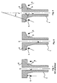
- FIG. 1 a pouring tube according to the state of the art and the resulting force of vertical thrust applied to the flat bearing faces.
- FIG. 2 represents a pouring tube according to the invention and the resulting pushing force applied to the flat bearing faces.
- FIG. 3 represents a pouring tube according to the invention, the angles ⁇ and ⁇ respectively represent the angle formed by the resulting pushing force with the axis of the pouring channel and the angle formed by the planar bearing face with the axis of the sprue.
- FIG. 4 represents a clamping device according to the state of the art.
- FIG. 5 represents an embodiment of a clamping device according to the invention.
- FIG. 1 represents a pouring tube (1) of the state of the art comprising a plate (2) and a tubular part (3).
- the flat bearing faces (5) form an angle ⁇ of 90 ° with the axis of the pouring channel (7).
- the pushing force (4) is vertical, parallel to the axis of the casting (7).
- the stresses generated in the pouring tube (4) of the prior art can be responsible for the formation of cracks at the upper end of the tubular part (3).
- FIGS 2 and 3 show a pouring tube (1) according to the invention.
- the plate (2) of pouring tube (1) is somewhat truncated.
- the flat bearing faces (5) form a angle ⁇ from 20 ° to 80 ° and this, without requiring an increase in the amount of material of the plate (2).
- Figure 3 shows the angles ⁇ and ⁇ .
- the resulting pushing force and the axis of the channel of casting form an angle ⁇ of 21 °.
- the flat bearing faces and the axis of the pouring channel form an angle ⁇ of 69 °.
- Figure 4 shows a clamping device (8) of the prior art. Strength resulting from thrust (4) is applied vertically, parallel to the casting axis (7), by through a rocker arm (10).
- FIG. 5 represents a clamping device (8) according to the invention.
- the resulting force of thrust (4) is applied via a rocker arm (10).
- Figure 6 shows a clamping device (8) according to the invention.
- the resulting force of thrust (4) is applied directly to the bearing faces thanks to the springs (11).
Abstract
Description
La présente invention se rapporte à un tube de coulée pour la conduite d'un métal liquide d'un récipient métallurgique supérieur vers un récipient métallurgique inférieur. En particulier, elle concerne un tube de coulée en matériau réfractaire pour le transfert d'acier liquide d'un répartiteur vers une lingotière ou, alternativement, d'une poche de coulée vers un répartiteur.The present invention relates to a pouring tube for the conduct of a liquid metal from an upper metallurgical vessel to a lower metallurgical vessel. In particular, it concerns a pouring tube of refractory material for the transfer of liquid steel from a distributor to an ingot mold or, alternatively, from a ladle to a distributor.
Les tubes de coulée destinés à conduire le métal en fusion d'un récipient métallurgique vers un autre en le protégeant des attaques chimiques et en l'isolant thermiquement de l'atmosphère environnante sont des pièces d'usure fortement sollicitées au point que leur durée de service peut limiter le temps de coulée. Des dispositifs d'amenée et d'échange de tube décrits récemment dans l'état de la technique ont permis de résoudre ce problème (voir par exemple les brevets européens 192,019 et 441,927). Dès que par exemple l'érosion de la paroi externe du tube au voisinage du ménisque, ou la formation d'un dépôt à l'intérieur du tube de coulée, atteint un certain niveau, le tube usé est remplacé par un nouveau tube en un laps de temps suffisamment court pour ne pas devoir interrompre la coulée.Pouring tubes intended to conduct the molten metal of a metallurgical vessel towards another by protecting it from chemical attacks and by thermally insulating it from the surrounding atmosphere are wear parts that are under heavy stress to the point that their service may limit the casting time. Tube supply and exchange devices described recently in the state of the art have made it possible to solve this problem (see for example the European patents 192,019 and 441,927). As soon as for example the erosion of the external wall of the tube near the meniscus, or the formation of a deposit inside the pouring tube, reaches a certain level, the worn tube is replaced by a new tube in a sufficiently short period of time short so as not to have to interrupt the casting.
Dans ces dispositifs, on utilise généralement un tube de coulée constitué d'une partie tubulaire délimitant un canal de coulée et, à son extrémité supérieure, d'une plaque pourvue d'un orifice délimitant un canal de coulée, ladite plaque comprenant une face supérieure assurant le contact avec la pièce amont du canal de coulée et une face inférieure formant l'interface avec la partie inférieure du tube, ladite face inférieure comprenant deux faces planes d'appui situées de part et d'autre du canal de coulée.In these devices, one generally uses a pouring tube made up of a part tubular delimiting a pouring channel and, at its upper end, a plate provided with a orifice delimiting a pouring channel, said plate comprising an upper face ensuring the contact with the upstream part of the casting channel and a lower face forming the interface with the lower part of the tube, said lower face comprising two flat bearing faces located on either side of the sprue.
Le tube est destiné à coulisser dans des guides contre la face inférieure plane soit d'un orifice de coulée telle qu'une busette interne, soit d'une plaque de fond fixe accolée à un tel orifice de coulée, soit d'une plaque fixe accolée à un mécanisme de régulation du jet de coulée insérée entre l'orifice de coulée (busette interne par exemple) et le tube de coulée. Il est bien clair que dans le contexte de la présente invention, lorsque l'on se réfère à un tube de coulée, il s'agit bien de ce tube destiné à coulisser dans un dispositif et non pas d'un tube fixe comme une busette interne.The tube is intended to slide in guides against the flat underside of either pouring orifice such as an internal nozzle, or of a fixed bottom plate attached to such an orifice of casting, either of a fixed plate attached to a mechanism for regulating the inserted casting jet between the pouring hole (internal nozzle for example) and the pouring tube. It is quite clear that in the context of the present invention, when referring to a pouring tube, it is indeed this tube intended to slide in a device and not of a fixed tube like an internal nozzle.
Les dispositifs connus et notamment celui décrit dans le document EP 192,019 prévoient que le tube de coulée est monté coulissant sur des guides aptes à transmettre un effort de poussée vers le haut. Cet effort de poussée est obtenu par des ressorts montés à une distance respectable de l'orifice de coulée et agissant sur des leviers ou culbuteurs. Ces derniers transmettent la force de poussée aux faces planes d'appui de la plaque du tube de coulée. Cette poussée vers le haut applique de manière relativement étanche la plaque du tube de coulée contre la pièce réfractaire amont notamment une busette interne ou une plaque réfractaire.Known devices and in particular that described in document EP 192,019 provide that the pouring tube is slidably mounted on guides capable of transmitting a thrust force to the top. This thrust force is obtained by springs mounted at a respectable distance of the pouring orifice and acting on levers or rockers. These transmit force thrust on the flat bearing faces of the plate of the pouring tube. This push up relatively tightly applies the plate of the pouring tube against the refractory piece upstream including an internal nozzle or a refractory plate.
Les tubes de coulée peuvent être faits d'une seule pièce ou peuvent être constitué par un assemblage de plusieurs pièces réfractaires.The pouring tubes can be made in one piece or can be constituted by a assembly of several refractory parts.
Dans la plupart des cas, les faces latérales de la plaque, la face inférieure de la plaque et l'extrémité supérieure de la partie tubulaire du tube sont protégées par un boítier métallique.In most cases, the side faces of the plate, the underside of the plate and the upper end of the tubular part of the tube are protected by a metal case.
On a cependant souvent constaté l'apparition de fissures ou microfissures du tube de coulée au niveau de la jonction entre l'élément tubulaire et la plaque, localisées à l'extrémité supérieure de l'élément tubulaire. Ces fissures surviennent lors de la mise en service du tube ou pendant son utilisation. La fissuration peut avoir pour origine un excès de contraintes thermiques, de contraintes mécaniques ou de contraintes thermo-mécaniques. Ces contraintes sont générées par les forces de maintien du tube dans le dispositif, par des vibrations et par l'écoulement du métal liquide.However, it has often been observed the appearance of cracks or microcracks in the tube of poured at the junction between the tubular element and the plate, located at the end upper part of the tubular element. These cracks occur during the commissioning of the tube or during use. Cracking can originate from an excess of thermal stresses, mechanical constraints or thermo-mechanical constraints. These constraints are generated by the holding forces of the tube in the device, by vibrations and by the flow of metal liquid.
Dans certains cas, ces fissures entraínent la rupture de la pièce. Dans d'autres cas, et même si ces fissures possèdent une taille infime, il est nécessaire d'en tenir compte. L'étranglement constitué par le passage du métal liquide dans le tube crée en effet une dépression et, par voie de conséquence, provoque une aspiration importante de l'air ambiant. L'oxygène ou même l'azote atmosphérique sont des sources de contaminations importantes du métal liquide, en particulier de l'acier. En outre, sous l'action combinée de l'oxygène et des températures très élevées, le matériau réfractaire peut se dégrader considérablement au niveau de l'arrivée d'oxygène, c'est-à-dire de la fissure. Cette dégradation accentue encore la détérioration locale du matériau réfractaire et élargit la fissure au point qu'il peut s'avérer nécessaire d'arrêter la coulée.In some cases, these cracks cause the part to rupture. In other cases, and even if these cracks have a tiny size, it is necessary to take them into account. The throttle formed by the passage of liquid metal in the tube creates a depression indeed and, consequently, causes a significant suction of the ambient air. Oxygen or even atmospheric nitrogen are sources of significant contamination of the liquid metal, in especially steel. In addition, under the combined action of oxygen and very high temperatures high refractory material can degrade considerably at the inlet oxygen, that is, from the crack. This deterioration further accentuates the local deterioration of the refractory material and widens the crack to the point where it may be necessary to stop the casting.
Il existe dans l'état de la technique différents moyens pour améliorer la résistance à la fissuration des tubes.There are various means in the state of the art for improving resistance to cracking of the tubes.
On connaít, par exemple, l'emploi de matériaux réfractaires résistant mieux à la fissuration. Toutefois ces matériaux sont généralement sensibles à d'autres phénomènes tels que l'érosion ou la corrosion.We know, for example, the use of refractory materials better resistant to cracking. However, these materials are generally sensitive to other phenomena such as erosion or corrosion.
Un autre moyen décrit dans le document WO 00/35614 est l'emploi d'un boítier métallique renforcé en sa partie inférieure par des moyens mécaniques qui augmentent sa rigidité.Another means described in document WO 00/35614 is the use of a metal case reinforced in its lower part by mechanical means which increase its rigidity.
Le document EP 1,133,373, quant à lui, décrit un tube comprenant une zone d'interface amortissante entre l'enveloppe métallique et le tube réfractaire. Cette zone est dotée d'un matériau dont les propriétés thermiques sont telles qu'il reste solide aux températures ambiantes mais subit des déformations à des températures élevées. Cette zone tampon diminue le risque de formation de fissures ou microfissures générées par les contraintes thermo-mécaniques apparaissant lors du démarrage de la coulée.Document EP 1,133,373, for its part, describes a tube comprising an interface zone damping between the metal casing and the refractory tube. This area has a material whose thermal properties are such that it remains solid at ambient temperatures but undergoes deformations at high temperatures. This buffer zone reduces the risk of formation cracks or microcracks generated by thermo-mechanical stresses appearing during start of casting.
Malgré les avantages apportés à la technique par les solutions décrites ci-dessus et l'amélioration continue dont elles ont fait l'objet ces dernières années, il subsiste encore certains problèmes.Despite the advantages brought to the technique by the solutions described above and the continuous improvement they have undergone in recent years, there are still some problems.
En effet, dans les dispositifs connus d'amenée et d'échange de tube, la plaque subit toujours, perpendiculairement à sa surface, des contraintes de flexion importantes qui peuvent être responsables de la formation de fissures à l'extrémité supérieure de la partie tubulaire. On observe en effet que la plaque supérieure peut se déformer par flexion autour d'un axe parallèle à la direction des guides dans lesquels coulisse ladite plaque.In fact, in the known devices for supplying and exchanging tubes, the plate undergoes always, perpendicular to its surface, significant bending stresses which can be responsible for the formation of cracks at the upper end of the tubular part. We observe in fact that the upper plate can be deformed by bending around an axis parallel to the direction of the guides in which said plate slides.
Les solutions décrites ci-dessus permettent d'atténuer ces contraintes de flexion en les arrêtant ou en les diluant et ce en agissant sur le matériau lui-même ou sur les techniques d'assemblage des tubes. Ces solutions sont coûteuses et ne sont pas entièrement satisfaisantes. The solutions described above make it possible to attenuate these bending stresses by stopping or diluting them by acting on the material itself or on the techniques tube assembly. These solutions are expensive and are not entirely satisfactory.
La présente invention a pour objet un tube de coulée dont la forme est adaptée afin de mieux résister aux contraintes imposées lors de son utilisation et notamment aux contraintes liées au maintien du tube dans le dispositif.The present invention relates to a pouring tube whose shape is adapted in order to better resist the constraints imposed during its use and in particular the constraints linked maintaining the tube in the device.
Le tube a aussi une forme adaptée à recevoir un système de clamage qui engendre un profil de contraintes favorables.The tube also has a shape adapted to receive a clamping system which generates a favorable stress profile.
En particulier, la présente invention a pour objet un tube de coulée pour dispositif d'amenée et d'échange d'un tube constitué d'une partie tubulaire délimitant un canal de coulée et, à son extrémité supérieure, d'une plaque, pourvue d'un orifice délimitant un canal de coulée, ladite plaque comprenant une face supérieure assurant le contact avec la pièce amont du canal de coulée et une face inférieure formant l'interface avec la partie tubulaire du tube; ladite plaque comprenant deux faces planes d'appui situées du côté opposé à la face supérieure de la plaque et situées de part et d'autre du canal de coulée. Ce tube est caractérisé en ce que lesdites deux faces forment avec l'axe du canal de coulée un angle β de 20° à 80°. La partie tubulaire peut être de forme générale cylindrique, ovale ou conique. La plaque est préférentiellement de forme carrée ou rectangulaire.In particular, the subject of the present invention is a pouring tube for a supply device. and for exchanging a tube consisting of a tubular part delimiting a pouring channel and, at its upper end, of a plate, provided with an orifice delimiting a pouring channel, said plate comprising an upper face ensuring contact with the upstream part of the pouring channel and a lower face forming the interface with the tubular part of the tube; said plate comprising two flat support faces located on the side opposite to the upper face of the plate and located on either side across the runner. This tube is characterized in that said two faces form with the axis of the runner an angle β from 20 ° to 80 °. The tubular part can be of general shape cylindrical, oval or conical. The plate is preferably of square or rectangular shape.
La forme de la plaque selon l'invention permet d'améliorer la résistance à la fissuration et ce sans augmenter la quantité de matière dans la zone sensible à la fissuration. Les dimensions d'encombrement restent en fait sensiblement identiques à celles des tubes de l'état de la technique.The shape of the plate according to the invention makes it possible to improve the resistance to cracking and without increasing the amount of material in the crack-sensitive area. The dimensions dimensions remain in fact substantially identical to those of the tubes of the prior art.
Lorsque le tube selon l'invention est introduit dans un dispositif d'amenée et d'échange, lesdites deux faces d'appui sont parallèles à l'axe du changement de tube.When the tube according to the invention is introduced into a supply and exchange device, said two bearing faces are parallel to the axis of the tube change.
Il a été remarqué qu'un angle β de 30° à 60°, et en particulier un angle proche de 45° donne de bons résultats en ce qui concerne la résistance à la fissuration et le profil de contraintes. Les contraintes de traction mesurées dans un tube de coulée au niveau de la zone critique pour un angle de 45° sont de 40 à 50 % inférieures à celle mesurées pour un angle de 90° correspondant à l'état de la technique.It has been noted that an angle β from 30 ° to 60 °, and in particular an angle close to 45 ° gives good results as regards the resistance to cracking and the stress profile. The tensile stresses measured in a pouring tube at the level of the critical zone for a 45 ° angle are 40 to 50% less than that measured for a 90 ° angle corresponding to the state of the art.
Selon une réalisation particulière de l'invention, la plaque du tube est asymétrique par rapport au plan perpendiculaire aux faces d'appui de la plaque du tube et comprenant l'axe du canal de coulée. Dès lors, la surface utile de la plaque de part et d'autre de ce plan est différente. Ceci permet d'amener un tube dans deux positions, une position de coulée dans laquelle l'orifice de la plaque correspond au canal de coulée amont et une position intermédiaire où l'orifice de la plaque ne communique pas avec le canal de coulée amont afin d'obstruer celui-ci. Ceci s'avère utile lorsque le système de fermeture amont assuré par exemple par la quenouille est défectueux. Il permet aussi de ne plus utiliser de plaque de sécurité puisque la fermeture peut être assurée par la plaque du tube elle-même.According to a particular embodiment of the invention, the plate of the tube is asymmetrical by relative to the plane perpendicular to the bearing faces of the tube plate and comprising the axis of the pouring channel. Consequently, the useful surface of the plate on either side of this plane is different. This allows a tube to be brought into two positions, a pouring position in which the orifice the plate corresponds to the upstream casting channel and an intermediate position where the orifice of the plate does not communicate with the upstream pouring channel in order to obstruct it. This turns out useful when the upstream closing system provided for example by the stopper rod is defective. It also makes it possible to no longer use a safety plate since the closure can be ensured by the tube plate itself.
La forme du tube selon l'invention permet également l'utilisation d'un dispositif de clamage différent de ceux utilisés dans l'état de la technique.The shape of the tube according to the invention also allows the use of a clamping device different from those used in the prior art.
La présente invention a donc également pour objet un dispositif de clamage d'un tube de coulée pour dispositif d'amenée et d'échange d'un tube. Le dispositif de clamage selon l'invention est caractérisé en ce que la force résultante de poussée est appliquée selon une direction formant un angle α de 10° à 70° avec l'axe du canal de coulée. The present invention therefore also relates to a device for clamping a tube of casting for a device for supplying and exchanging a tube. The clamping device according to the invention is characterized in that the resulting pushing force is applied in a direction forming an angle α of 10 ° to 70 ° with the axis of the pouring channel.
Le dispositif de clamage exerce sur les faces d'appui de la plaque du tube de coulée une force de poussée, non pas dirigée vers le haut parallèlement à l'axe de coulée comme dans les dispositifs existants, mais oblique par rapport à celui-ci et dirigée vers le canal de coulée.The clamping device exerts on the bearing faces of the plate of the pouring tube a pushing force, not directed upwards parallel to the casting axis as in existing devices, but oblique to it and directed towards the pouring channel.
Les contraintes de flexion dans le tube de coulée engendrées par un tel dispositif de clamage sont inférieures à celles des dispositifs de l'état de la technique. La force résultante de poussée comporte une composante verticale qui assure le contact et l'étanchéité avec la pièce amont et une composante horizontale. Cette composante horizontale est favorable puisqu'elle met le matériau réfractaire en compression ce qui permet de réduire l'apparition de fissures et/ou de limiter leur propagation.The bending stresses in the pouring tube generated by such a device claims are lower than those of the prior art devices. The resulting force of thrust has a vertical component which ensures contact and sealing with the part upstream and a horizontal component. This horizontal component is favorable since it puts the refractory material in compression which makes it possible to reduce the appearance of cracks and / or limit their spread.
La force résultante de poussée du dispositif de clamage selon l'invention doit être appliquée avec un angle α de 10° à 70°. En effet, un angle inférieur à 10° revient à appliquer une force quasi verticale comme dans les dispositifs connus et n'a pas d'influence positive significative sur le phénomène de fissuration. Lorsque la force est appliquée avec un angle supérieur à 70°, la composante verticale de la force n'est plus suffisante pour assurer un bon contact et une bonne étanchéité entre la plaque du tube de coulée et la pièce amont.The resulting pushing force of the clamping device according to the invention must be applied with an angle α from 10 ° to 70 °. Indeed, an angle less than 10 ° amounts to applying a quasi-vertical force as in the known devices and has no significant positive influence on the phenomenon of cracking. When the force is applied at an angle greater than 70 °, the vertical component of the force is no longer sufficient to ensure good contact and good sealing between the pouring tube plate and the upstream part.
Il a été remarqué qu'un angle de poussée α de 30° à 60°, et en particulier un angle proche de 45° donne de bons résultats en ce qui concerne la résistance à la fissuration et le profil de contraintes. Les contraintes de traction mesurées dans un tube de coulée au niveau de la zone critique pour un angle de poussée de 45° sont de 40 à 50 % inférieures à celles mesurées pour un angle de poussée de 90° correspondant à l'état de la technique. Un angle de 45° est un bon compromis entre la composante verticale de la force de poussée qui assure l'étanchéité entre le tube et la pièce amont et la composante horizontale de la force. En effet une composante verticale minimum est nécessaire afin de permettre un contact étanche entre le tube et le pièce amont. Plus l'angle α augmente et plus grande doit être la force de poussée pour assurer une même composante verticale. Une force de poussée trop élevée engendre des problèmes mécaniques non négligeables, notamment une sollicitation accrue des ressorts et une diminution de leur durée de vie.It has been observed that a thrust angle α from 30 ° to 60 °, and in particular a close angle of 45 ° gives good results with regard to the resistance to cracking and the profile of constraints. The tensile stresses measured in a pouring tube at the level of the area critical for a 45 ° thrust angle are 40 to 50% lower than those measured for a thrust angle of 90 ° corresponding to the state of the art. A 45 ° angle is a good compromise between the vertical component of the thrust force which seals between the tube and the upstream part and the horizontal component of the force. Indeed a vertical component minimum is necessary to allow tight contact between the tube and the upstream part. More the angle α increases and greater must be the pushing force to ensure the same vertical component. Too high a push force causes mechanical problems non-negligible, in particular increased stress on the springs and a reduction in their duration of life.
Un angle de 45° permet également une réalisation aisée du tube de coulée et du dispositif de clamage.An angle of 45 ° also allows easy production of the pouring tube and the device of clamor.
La force de poussée peut être appliquée directement sur la face d'appui de la plaque du tube de coulée, par exemple au moyen de ressorts ou par l'intermédiaire d'un élément tel qu'un culbuteur.The pushing force can be applied directly to the bearing face of the plate of the pouring tube, for example by means of springs or by means of an element such as rocker.
Un autre aspect de l'invention est une installation de coulée comprenant un mécanisme d'amenée et d'échange de tube, comprenant un tube de coulée selon l'invention et un dispositif de clamage selon l'invention.Another aspect of the invention is a casting installation comprising a mechanism tube supply and exchange, comprising a pouring tube according to the invention and a device for clamage according to the invention.
Le tube de coulée est maintenu en contact étanche avec la pièce de coulée amont au moyen du dispositif de clamage. La force de poussée du dispositif de clamage étant appliquée sur les deux faces planes d'appui de la plaque du tube de coulée. L'installation de coulée comprend également un système de glissière-guide adapté à recevoir les deux faces d'appui du tube de coulée et permettant d'amener un nouveau tube de coulée en position de coulée et de chasser le tube de coulée usagé en dehors de la position de coulée.The pouring tube is kept in tight contact with the upstream casting part at the by means of the clamping device. The pushing force of the clamping device being applied to the two flat bearing faces of the plate of the pouring tube. The casting installation includes also a guide rail system adapted to receive the two bearing faces of the tube pouring and allowing to bring a new pouring tube in the pouring position and to drive out the used pouring tube outside the pouring position.
Le système de glissière présente une surface d'appui dont l'angle forme avec l'axe de coulée un angle sensiblement égal à l'angle β que forment les faces d'appui de la plaque du tube de coulée avec ledit axe de coulée.The slide system has a bearing surface whose angle forms with the axis of casting an angle substantially equal to the angle β formed by the bearing faces of the tube plate casting with said casting axis.
Afin de permettre une meilleure compréhension de l'invention, celle-ci va maintenant être décrite sur base des figures illustrant des formes particulières de réalisation de l'invention, sans qu'il ne faille toutefois y voir une quelconque limitation de celle-ci.In order to allow a better understanding of the invention, it will now be described on the basis of the figures illustrating particular embodiments of the invention, without however, it should not be seen as any limitation whatsoever.
Sur ces figures, on a représenté à la figure 1 un tube de coulée selon l'état de la technique
et la force résultante de poussée verticale appliquée aux faces plane d'appui.
La figure 2 représente un tube de coulée selon l'invention et la force résultante de poussée
appliquée aux faces planes d'appui.
La figure 3 représente un tube de coulée selon l'invention, les angles α et β représentent
respectivement l'angle que forme la force résultante de poussée avec l'axe du canal de coulée et
l'angle que forme la face plane d'appui avec l'axe du canal de coulée.
La figure 4 représente un dispositif de clamage selon l'état de la technique.
La figure 5 représente un mode de réalisation d'un dispositif de clamage selon l'invention.In these figures, there is shown in Figure 1 a pouring tube according to the state of the art and the resulting force of vertical thrust applied to the flat bearing faces.
FIG. 2 represents a pouring tube according to the invention and the resulting pushing force applied to the flat bearing faces.
FIG. 3 represents a pouring tube according to the invention, the angles α and β respectively represent the angle formed by the resulting pushing force with the axis of the pouring channel and the angle formed by the planar bearing face with the axis of the sprue.
FIG. 4 represents a clamping device according to the state of the art.
FIG. 5 represents an embodiment of a clamping device according to the invention.
La figure 1 représente un tube de coulée (1) de l'état de la technique comprenant une plaque (2) et une partie tubulaire (3). Les faces plane d'appui (5) forment un angle β de 90° avec l'axe du canal de coulée (7). La force de poussée (4) est verticale, parallèle à l'axe du canal de coulée (7). Les contraintes générées dans le tube de coulée (4) de l'état de la technique peuvent être responsables de la formation de fissures à l'extrémité supérieure de la partie tubulaire (3).FIG. 1 represents a pouring tube (1) of the state of the art comprising a plate (2) and a tubular part (3). The flat bearing faces (5) form an angle β of 90 ° with the axis of the pouring channel (7). The pushing force (4) is vertical, parallel to the axis of the casting (7). The stresses generated in the pouring tube (4) of the prior art can be responsible for the formation of cracks at the upper end of the tubular part (3).
Les figures 2 et 3 représentent un tube de coulée (1) selon l'invention. La plaque (2) du tube de coulée (1) est d'une certaine manière tronquée. Les faces planes d'appui (5) forment un angle β de 20° à 80° et ce, sans nécessiter une augmentation de la quantité de matière de la plaque (2).Figures 2 and 3 show a pouring tube (1) according to the invention. The plate (2) of pouring tube (1) is somewhat truncated. The flat bearing faces (5) form a angle β from 20 ° to 80 ° and this, without requiring an increase in the amount of material of the plate (2).
La figure 3 représente les angles α et β. La force résultante de poussée et l'axe du canal de coulée forment un angle α de 21°. Les faces planes d'appui et l'axe du canal de coulée forment un angle β de 69°.Figure 3 shows the angles α and β. The resulting pushing force and the axis of the channel of casting form an angle α of 21 °. The flat bearing faces and the axis of the pouring channel form an angle β of 69 °.
La figure 4 représente un dispositif de clamage (8) de l'état de la technique. La force résultante de poussée (4) est appliquée verticalement, parallèlement à l'axe de coulée (7), par l'intermédiaire d'un culbuteur (10).Figure 4 shows a clamping device (8) of the prior art. Strength resulting from thrust (4) is applied vertically, parallel to the casting axis (7), by through a rocker arm (10).
La figure 5 représente un dispositif de clamage (8) selon l'invention. La force résultante de poussée (4) est appliquée par l'intermédiaire d'un culbuteur (10).FIG. 5 represents a clamping device (8) according to the invention. The resulting force of thrust (4) is applied via a rocker arm (10).
La figure 6 représente un dispositif de clamage (8) selon l'invention. La force résultante de poussée (4) est appliquée directement aux faces d'appui grâce aux ressorts (11). Figure 6 shows a clamping device (8) according to the invention. The resulting force of thrust (4) is applied directly to the bearing faces thanks to the springs (11).
- 1.1.
- Tube de couléePouring tube
- 2.2.
- PlaquePlate
- 3.3.
- Partie tubulaireTubular part
- 4.4.
- Force résultante de pousséeResulting thrust force
- 5.5.
- Face plane d'appuiFlat support face
- 6.6.
- Canal de couléePouring channel
- 7.7.
- Axe de couléeCasting axis
- 8.8.
- Dispositif de clamageClamming device
- 9.9.
- Busette interneInternal nozzle
- 10.10.
- Culbuteurtumbler
- 11.11.
- RessortSpring
Claims (8)
Priority Applications (27)
| Application Number | Priority Date | Filing Date | Title |
|---|---|---|---|
| EP03447014A EP1439016A1 (en) | 2003-01-20 | 2003-01-20 | Casting tube, clamping device for a casting tube and casting machine |
| ARP040100100A AR042883A1 (en) | 2003-01-20 | 2004-01-15 | COLADA TUBE, PUSHING DEVICE FOR A COLADA TUBE AND COLADA INSTALLATION |
| CL200400059A CL43158B (en) | 2003-01-20 | 2004-01-16 | COLADA TUBE FOR LIQUID METAL DRIVING CONSTITUTED BY A TUBULAR PART DELIVERING A CHANNEL, A PLATE PROVIDED WITH A HOLE, CONTAINING TWO SIDES A SUPERIOR AND A LOWER SUCH SUPPORT FACES FORM WITH THE AXIS OF THE COLADA CHANNEL |
| TW093101167A TWI307645B (en) | 2003-01-20 | 2004-01-16 | Casting nozzle, clamping device for a casting nozzle and casting installation |
| PT04703122T PT1590114E (en) | 2003-01-20 | 2004-01-19 | LEAK NOZZLE, IMPULSE DEVICE FOR A LEAK NOZZLE AND FOUNDATION INSTALLATION |
| PCT/BE2004/000010 WO2004065041A1 (en) | 2003-01-20 | 2004-01-19 | Pouring nozzle, pushing device for a pouring nozzle and casting installation |
| KR1020057013319A KR101061405B1 (en) | 2003-01-20 | 2004-01-19 | Injection nozzle, press device of this injection nozzle, casting equipment |
| AT04703122T ATE320873T1 (en) | 2003-01-20 | 2004-01-19 | CASTING NOZZLE, PRESSURE DEVICE FOR A CASTING NOZZLE AND CASTING SYSTEM |
| PL378020A PL207935B1 (en) | 2003-01-20 | 2004-01-19 | Pouring nozzle, pushing device for a pouring nozzle and casting installation |
| SI200430025T SI1590114T2 (en) | 2003-01-20 | 2004-01-19 | Pouring nozzle, pushing device for a pouring nozzle and casting installation |
| CNB2004800000449A CN1325208C (en) | 2003-01-20 | 2004-01-19 | Casting tube, clamping device for a casting tube and casting machine |
| DE602004000532T DE602004000532T3 (en) | 2003-01-20 | 2004-01-19 | GIESS NOZZLE, PRESSURE DEVICE FOR A GIESS NOZZLE AND CASTING SYSTEM |
| JP2006500421A JP2006515803A (en) | 2003-01-20 | 2004-01-19 | Injection nozzle, injection nozzle pressing device and casting device |
| EP04703122A EP1590114B2 (en) | 2003-01-20 | 2004-01-19 | Pouring nozzle, pushing device for a pouring nozzle and casting installation |
| UAA200508057A UA79533C2 (en) | 2003-01-20 | 2004-01-19 | Pouring nozzle, pushing device for pouring nozzle and casting installation |
| ES04703122T ES2262112T5 (en) | 2003-01-20 | 2004-01-19 | COLADA TUBE, PUSHING DEVICE FOR A COLADA TUBE AND COLADA INSTALLATION. |
| MXPA05007688A MXPA05007688A (en) | 2003-01-20 | 2004-01-19 | Pouring nozzle, pushing device for a pouring nozzle and casting installation. |
| EA200501021A EA006691B1 (en) | 2003-01-20 | 2004-01-19 | Pouring nozzle, device for nozzle insertion and/or removal and casting installation |
| ZA200505390A ZA200505390B (en) | 2003-01-20 | 2004-01-19 | Pouring nozzle, pushing device for a pouring nozzle and casting installation |
| AU2004205428A AU2004205428B2 (en) | 2003-01-20 | 2004-01-19 | Pouring nozzle, pushing device for a pouring nozzle and casting installation |
| BRPI0406798-3A BRPI0406798B1 (en) | 2003-01-20 | 2004-01-19 | LEAK NOZZLE, INSERT AND / OR REMOVAL FOR A LEAKING AND LANGUAGE INSTALLATION |
| US10/542,698 US8127972B2 (en) | 2003-01-20 | 2004-01-19 | Pouring nozzle, pushing device for a pouring nozzle and casting installation |
| CA2513116A CA2513116C (en) | 2003-01-20 | 2004-01-19 | Pouring nozzle, pushing device for a pouring nozzle and casting installation |
| EGNA2005000401 EG23879A (en) | 2003-01-20 | 2005-07-20 | Pouring nozzle, pushing device for a pouring nozzle and casting installation |
| MA28437A MA27620A1 (en) | 2003-01-20 | 2005-08-12 | CASTING NOZZLE, PUSHING DEVICE FOR CASTING NOZZLE, AND CASTING INSTALLATION |
| JP2011058475A JP2011115859A (en) | 2003-01-20 | 2011-03-16 | Pouring nozzle, pushing device for the same, and casting installation |
| JP2013233449A JP5926230B2 (en) | 2003-01-20 | 2013-11-11 | Injection nozzle, injection nozzle pressing device and casting device |
Applications Claiming Priority (1)
| Application Number | Priority Date | Filing Date | Title |
|---|---|---|---|
| EP03447014A EP1439016A1 (en) | 2003-01-20 | 2003-01-20 | Casting tube, clamping device for a casting tube and casting machine |
Publications (1)
| Publication Number | Publication Date |
|---|---|
| EP1439016A1 true EP1439016A1 (en) | 2004-07-21 |
Family
ID=32524313
Family Applications (2)
| Application Number | Title | Priority Date | Filing Date |
|---|---|---|---|
| EP03447014A Withdrawn EP1439016A1 (en) | 2003-01-20 | 2003-01-20 | Casting tube, clamping device for a casting tube and casting machine |
| EP04703122A Expired - Lifetime EP1590114B2 (en) | 2003-01-20 | 2004-01-19 | Pouring nozzle, pushing device for a pouring nozzle and casting installation |
Family Applications After (1)
| Application Number | Title | Priority Date | Filing Date |
|---|---|---|---|
| EP04703122A Expired - Lifetime EP1590114B2 (en) | 2003-01-20 | 2004-01-19 | Pouring nozzle, pushing device for a pouring nozzle and casting installation |
Country Status (24)
| Country | Link |
|---|---|
| US (1) | US8127972B2 (en) |
| EP (2) | EP1439016A1 (en) |
| JP (3) | JP2006515803A (en) |
| KR (1) | KR101061405B1 (en) |
| CN (1) | CN1325208C (en) |
| AR (1) | AR042883A1 (en) |
| AT (1) | ATE320873T1 (en) |
| AU (1) | AU2004205428B2 (en) |
| BR (1) | BRPI0406798B1 (en) |
| CA (1) | CA2513116C (en) |
| CL (1) | CL43158B (en) |
| DE (1) | DE602004000532T3 (en) |
| EA (1) | EA006691B1 (en) |
| EG (1) | EG23879A (en) |
| ES (1) | ES2262112T5 (en) |
| MA (1) | MA27620A1 (en) |
| MX (1) | MXPA05007688A (en) |
| PL (1) | PL207935B1 (en) |
| PT (1) | PT1590114E (en) |
| SI (1) | SI1590114T2 (en) |
| TW (1) | TWI307645B (en) |
| UA (1) | UA79533C2 (en) |
| WO (1) | WO2004065041A1 (en) |
| ZA (1) | ZA200505390B (en) |
Cited By (6)
| Publication number | Priority date | Publication date | Assignee | Title |
|---|---|---|---|---|
| WO2011113596A1 (en) * | 2010-03-19 | 2011-09-22 | Vesuvius Group S.A. | Device for holding and replacing a casting plate in a casting installation, metallic casing of casting plate and casting plate, provided with means interacting with a device detector |
| EP2368654A1 (en) * | 2010-03-19 | 2011-09-28 | Vesuvius Group S.A | Device for holding and changing a pouring plate in a pouring facility, metal enclosure of the pouring plate and pouring plate provided with means engaging with a detector of the device. |
| EP2386368A1 (en) * | 2010-03-19 | 2011-11-16 | Vesuvius Group S.A | Internal nozzle for transferring liquid metal contained in a container, system for clamping said nozzle and pouring device |
| CN103180068A (en) * | 2010-10-20 | 2013-06-26 | 维苏维尤斯集团有限公司 | Tube for pouring liquid metal, assembly of a tube and a metal frame and metal frame |
| CN104540619A (en) * | 2012-09-11 | 2015-04-22 | 里弗雷克特里知识产权两合公司 | Refractory pouring device |
| RU2562870C2 (en) * | 2010-03-19 | 2015-09-10 | Везувиус Груп С.А. | Inner nozzle for teeming of fused metal from metal vessel and method of its fabrication |
Families Citing this family (16)
| Publication number | Priority date | Publication date | Assignee | Title |
|---|---|---|---|---|
| JP4604092B2 (en) * | 2008-01-07 | 2010-12-22 | 品川リフラクトリーズ株式会社 | Immersion nozzle support exchange mechanism and lower nozzle / immersion nozzle sealing method |
| JP2010188398A (en) * | 2009-02-19 | 2010-09-02 | Kurosaki Harima Corp | Sliding nozzle apparatus |
| ATE510641T1 (en) * | 2009-07-01 | 2011-06-15 | Refractory Intellectual Prop | POURING NOZZLE |
| EP2368655A1 (en) * | 2010-03-19 | 2011-09-28 | Vesuvius Group S.A | Plate for transferring liquid metal contained in a metalworking container, frame and device for changing such a plate |
| RU2466825C2 (en) * | 2010-03-30 | 2012-11-20 | Акети Керамикс Ко., Лтд. | Teeming nozzle for continuous casting |
| TR201815687T4 (en) | 2010-03-30 | 2018-11-21 | Akechi Ceram Co Ltd | Casting nozzle. |
| CN101966582B (en) * | 2010-10-28 | 2012-07-04 | 黄石市火炬科技实业有限责任公司 | Quick-change water port device with argon introducing function for continuous casting tundish |
| CN101966581A (en) * | 2010-10-29 | 2011-02-09 | 维苏威高级陶瓷(苏州)有限公司 | Tundish mechanism for continuous casting |
| CH704928B1 (en) * | 2011-05-06 | 2023-10-13 | Stopinc Ag | Device for attaching a perforated brick and perforated brick. |
| AU2014336310B2 (en) | 2013-10-14 | 2018-05-17 | Vesuvius Group (Sa) | Coupling device for reversibly coupling a ladle shroud to a collector nozzle, self-supported ladle shroud, kit thereof and method for coupling a ladle shroud to a collector nozzle |
| CN112570696B (en) * | 2014-05-21 | 2022-07-19 | 诺维尔里斯公司 | Mixing injector nozzle and flow control device |
| TWI659786B (en) * | 2015-02-16 | 2019-05-21 | 比利時商維蘇威集團股份有限公司 | Coupling device for reversibly coupling a ladle shroud to a collector nozzle, self-supported ladle shroud, kit thereof and method for coupling a ladle shroud to a collector nozzle |
| TWI633956B (en) * | 2016-08-09 | 2018-09-01 | Ak鋼鐵資產公司 | Tundish funnel,collector and casting machine |
| CN107470570A (en) * | 2017-07-19 | 2017-12-15 | 重庆市翔聪机械制造有限公司 | A kind of flywheel casting mould |
| EP3587002B1 (en) * | 2018-06-26 | 2020-12-16 | Refractory Intellectual Property GmbH & Co. KG | Sliding closure for a metallurgical vessel |
| CN115041675A (en) * | 2022-08-11 | 2022-09-13 | 北京科技大学 | Composite water gap and preparation process thereof |
Citations (3)
| Publication number | Priority date | Publication date | Assignee | Title |
|---|---|---|---|---|
| GB1593372A (en) * | 1977-09-23 | 1981-07-15 | Didier Werke Ag | Refractory structures |
| US4995535A (en) * | 1989-04-21 | 1991-02-26 | Toshiba Ceramics Co., Ltd. | Nozzle device for discharging molten metal |
| WO2001081028A1 (en) * | 2000-04-21 | 2001-11-01 | Vesuvius Crucible Company | One-piece inner nozzle and clamping device for holding such a nozzle |
Family Cites Families (31)
| Publication number | Priority date | Publication date | Assignee | Title |
|---|---|---|---|---|
| JPS4944008Y2 (en) * | 1971-11-22 | 1974-12-03 | ||
| GB1593371A (en) * | 1976-06-25 | 1981-07-15 | Didier Werke Ag | Refractory structures |
| US4543981A (en) † | 1981-11-26 | 1985-10-01 | Uss Engineers & Consultants, Inc. | Sliding gate valves |
| DE3318994C1 (en) | 1983-05-25 | 1984-11-08 | Multivac Sepp Haggenmüller KG, 8941 Wolfertschwenden | Unwinding device |
| BE901564A (en) * | 1985-01-24 | 1985-07-24 | Szadkowski Stanislav | DEVICE FOR FEEDING AND EXCHANGING A CASTING TUBE. |
| CN1008150B (en) * | 1985-10-10 | 1990-05-30 | 美国钢铁工程及顾问公司 | Replaceable wear parts for sliding-gate valve |
| US4951851A (en) * | 1986-11-17 | 1990-08-28 | Flo-Con Systems, Inc. | Tube holder and method |
| US5188743A (en) * | 1989-03-03 | 1993-02-23 | Flo-Con Systems, Inc. | Plate, changer, plate and method |
| US5044533A (en) † | 1990-10-01 | 1991-09-03 | Flo-Con Systems, Inc. | Clamp for bandless refractory and method |
| BE1004402A6 (en) * | 1989-08-30 | 1992-11-17 | Internat Ind Engineering S A | CASTING FOR A CONTAINER closable OR STEEL METALLURGICAL. |
| JP2522706B2 (en) * | 1989-10-03 | 1996-08-07 | 富士写真フイルム株式会社 | Line sensor connection deviation detection method |
| JPH0718458Y2 (en) * | 1990-03-26 | 1995-05-01 | ハリマセラミック株式会社 | Mounting structure for upper and lower split nozzles to molten metal container |
| JPH0433771A (en) * | 1990-05-29 | 1992-02-05 | Kurosaki Refract Co Ltd | Device for closing nozzle for molten metal |
| WO1992000821A1 (en) * | 1990-07-04 | 1992-01-23 | International Industrial Engineering S.A. | Improved pouring tube insertion and replacement device |
| DE4023077A1 (en) * | 1990-07-20 | 1992-01-23 | Didier Werke Ag | Replacement of nozzle into continuous casting mould - moves nozzle into place from waiting position which pushes used nozzle aside |
| JP2678251B2 (en) * | 1991-08-16 | 1997-11-17 | 住友金属工業株式会社 | Immersion nozzle holding device |
| US5688425A (en) * | 1994-05-06 | 1997-11-18 | Shinagawa Shirorenga Kabushiki Kaisha | Submerged nozzle changing apparatus |
| CN2242745Y (en) * | 1995-07-07 | 1996-12-18 | 杨玉富 | Improved liquid-steel ladle gate |
| JP3523965B2 (en) * | 1996-09-12 | 2004-04-26 | 品川白煉瓦株式会社 | Immersion nozzle changer |
| JPH10211570A (en) * | 1997-01-28 | 1998-08-11 | Toshiba Ceramics Co Ltd | Device for supporting pouring nozzle in vessel for casting |
| JP3031541B2 (en) * | 1997-04-14 | 2000-04-10 | 住友重機械鋳鍛株式会社 | Tundish nozzle changer for continuous casting machine |
| JP4099257B2 (en) * | 1998-02-18 | 2008-06-11 | 黒崎播磨株式会社 | Lower nozzle for discharging molten metal |
| CN1120448C (en) | 1998-09-09 | 2003-09-03 | 英业达股份有限公司 | Processing metho for implementing visual effect of explosion on display and computer system using it |
| GB9825986D0 (en) † | 1998-11-27 | 1999-01-20 | Didier Werke Ag | Improvements in or relating to refractory products |
| BE1013024A3 (en) * | 1998-12-15 | 2001-08-07 | Internat Ind Engineering S A | Casting tube |
| EP1132163A1 (en) * | 2000-03-07 | 2001-09-12 | Vesuvius Crucible Company | Grooved refractory part used for metallurgical casting, assembly of refractory parts, casting installation and process for restoring a surface of a metallurgical part |
| JP3506655B2 (en) * | 2000-04-28 | 2004-03-15 | 明智セラミックス株式会社 | Continuous casting nozzle |
| CN2437435Y (en) * | 2000-08-11 | 2001-07-04 | 莱芜钢铁股份有限公司炼钢厂 | Device for fast replacing casting sizing gate of tundish for continuous casting |
| JP4312948B2 (en) * | 2000-11-22 | 2009-08-12 | 明智セラミックス株式会社 | Immersion nozzle for continuous casting |
| JP2002283046A (en) * | 2001-03-27 | 2002-10-02 | Kurosaki Harima Corp | Nozzle holder, and nozzle fitting method thereby |
| CN2487471Y (en) | 2001-08-03 | 2002-04-24 | 马鞍山市双益机械制造有限公司 | Continuous casting nozzle ready-packaging machine |
-
2003
- 2003-01-20 EP EP03447014A patent/EP1439016A1/en not_active Withdrawn
-
2004
- 2004-01-15 AR ARP040100100A patent/AR042883A1/en active IP Right Grant
- 2004-01-16 CL CL200400059A patent/CL43158B/en active
- 2004-01-16 TW TW093101167A patent/TWI307645B/en not_active IP Right Cessation
- 2004-01-19 BR BRPI0406798-3A patent/BRPI0406798B1/en active IP Right Grant
- 2004-01-19 PL PL378020A patent/PL207935B1/en unknown
- 2004-01-19 KR KR1020057013319A patent/KR101061405B1/en active IP Right Grant
- 2004-01-19 CN CNB2004800000449A patent/CN1325208C/en not_active Ceased
- 2004-01-19 EA EA200501021A patent/EA006691B1/en not_active IP Right Cessation
- 2004-01-19 MX MXPA05007688A patent/MXPA05007688A/en active IP Right Grant
- 2004-01-19 UA UAA200508057A patent/UA79533C2/en unknown
- 2004-01-19 ZA ZA200505390A patent/ZA200505390B/en unknown
- 2004-01-19 US US10/542,698 patent/US8127972B2/en active Active
- 2004-01-19 DE DE602004000532T patent/DE602004000532T3/en not_active Expired - Lifetime
- 2004-01-19 JP JP2006500421A patent/JP2006515803A/en not_active Withdrawn
- 2004-01-19 ES ES04703122T patent/ES2262112T5/en not_active Expired - Lifetime
- 2004-01-19 WO PCT/BE2004/000010 patent/WO2004065041A1/en active IP Right Grant
- 2004-01-19 AT AT04703122T patent/ATE320873T1/en active
- 2004-01-19 PT PT04703122T patent/PT1590114E/en unknown
- 2004-01-19 EP EP04703122A patent/EP1590114B2/en not_active Expired - Lifetime
- 2004-01-19 CA CA2513116A patent/CA2513116C/en not_active Expired - Fee Related
- 2004-01-19 AU AU2004205428A patent/AU2004205428B2/en not_active Ceased
- 2004-01-19 SI SI200430025T patent/SI1590114T2/en unknown
-
2005
- 2005-07-20 EG EGNA2005000401 patent/EG23879A/en active
- 2005-08-12 MA MA28437A patent/MA27620A1/en unknown
-
2011
- 2011-03-16 JP JP2011058475A patent/JP2011115859A/en not_active Withdrawn
-
2013
- 2013-11-11 JP JP2013233449A patent/JP5926230B2/en not_active Expired - Fee Related
Patent Citations (3)
| Publication number | Priority date | Publication date | Assignee | Title |
|---|---|---|---|---|
| GB1593372A (en) * | 1977-09-23 | 1981-07-15 | Didier Werke Ag | Refractory structures |
| US4995535A (en) * | 1989-04-21 | 1991-02-26 | Toshiba Ceramics Co., Ltd. | Nozzle device for discharging molten metal |
| WO2001081028A1 (en) * | 2000-04-21 | 2001-11-01 | Vesuvius Crucible Company | One-piece inner nozzle and clamping device for holding such a nozzle |
Cited By (11)
| Publication number | Priority date | Publication date | Assignee | Title |
|---|---|---|---|---|
| WO2011113596A1 (en) * | 2010-03-19 | 2011-09-22 | Vesuvius Group S.A. | Device for holding and replacing a casting plate in a casting installation, metallic casing of casting plate and casting plate, provided with means interacting with a device detector |
| EP2368654A1 (en) * | 2010-03-19 | 2011-09-28 | Vesuvius Group S.A | Device for holding and changing a pouring plate in a pouring facility, metal enclosure of the pouring plate and pouring plate provided with means engaging with a detector of the device. |
| EP2386368A1 (en) * | 2010-03-19 | 2011-11-16 | Vesuvius Group S.A | Internal nozzle for transferring liquid metal contained in a container, system for clamping said nozzle and pouring device |
| US8602085B2 (en) | 2010-03-19 | 2013-12-10 | Vesuvius Group S.A. | Device with detector for holding and replacing a casting plate |
| AU2011229486B2 (en) * | 2010-03-19 | 2014-02-20 | Vesuvius Group S.A. | Device for holding and replacing a casting plate in a casting installation, metallic casing of casting plate and casting plate, provided with means interacting with a device detector |
| RU2562870C2 (en) * | 2010-03-19 | 2015-09-10 | Везувиус Груп С.А. | Inner nozzle for teeming of fused metal from metal vessel and method of its fabrication |
| RU2566134C2 (en) * | 2010-03-19 | 2015-10-20 | Везувиус Груп С.А. | Device for retaining and replacing of teeming plates in teeming unit, metal shell of teeming plate and teeming plate |
| US9770755B2 (en) | 2010-03-19 | 2017-09-26 | Vesuvius Group S.A. | Casting plate and casting plate casing with detector-engaging protrusion |
| CN103180068A (en) * | 2010-10-20 | 2013-06-26 | 维苏维尤斯集团有限公司 | Tube for pouring liquid metal, assembly of a tube and a metal frame and metal frame |
| CN103180068B (en) * | 2010-10-20 | 2015-04-22 | 维苏维尤斯集团有限公司 | Tube for pouring liquid metal, assembly of a tube and a metal frame and metal frame |
| CN104540619A (en) * | 2012-09-11 | 2015-04-22 | 里弗雷克特里知识产权两合公司 | Refractory pouring device |
Also Published As
Similar Documents
| Publication | Publication Date | Title |
|---|---|---|
| EP1439016A1 (en) | Casting tube, clamping device for a casting tube and casting machine | |
| EP2319640A1 (en) | Casting nozzle and assembly of such a nozzle with an inner nozzle | |
| FR2486429A1 (en) | METHOD FOR REPAIRING OR REPLACING REFRACTORY WEAR PARTS OF SLIDING SHUTTER DEVICES | |
| EP0508246B1 (en) | Stopper rod having an erosion-resistant sleeve | |
| FR2745211A1 (en) | DISTRIBUTOR HAVING A TUBE CHANGER AND PLATE FOR THE TUBE CHANGER | |
| CA2742862C (en) | Ladle pipe for liquid metal casting plant | |
| BE1013024A3 (en) | Casting tube | |
| BE1000948A3 (en) | Tube casting for closure device sliding. | |
| EP0346258B1 (en) | Casting gate for linear and symmetrie axial displacement | |
| CA2872977C (en) | Device for pouring molten glass | |
| FR2521462A1 (en) | Metal feed equipment for continuous casting - includes stopper extension creating back pressure in immersion nozzle | |
| EP0370934B1 (en) | Method of and device for alimentation of an ingot mold with molten metal in a continuous casting installation for thin blooms | |
| BE1008567A6 (en) | Seal joint structure for a metallurgical receptacle | |
| CA1153864A (en) | Dipping nozzles for electrorotating continuous pouring of liquid metals | |
| EP1132163A1 (en) | Grooved refractory part used for metallurgical casting, assembly of refractory parts, casting installation and process for restoring a surface of a metallurgical part | |
| FR2747062A1 (en) | CONTINUOUS CASTING LINGOTIERE FOR CONTINUOUS CASTING WITH VERTICAL METAL LOAD | |
| BE1012302A3 (en) | Stopper rod assembly | |
| EP0582496B1 (en) | Internal pouring tube made from refractory material for metallurgical vessels | |
| FR2745209A1 (en) | DRAWER DEVICE FOR TANK CONTAINING FUSED METAL | |
| FR2692505A1 (en) | Molten metal casting tube for pressure casting - consists of two sections connected by threaded joint having conical surfaces | |
| BE1008119A3 (en) | Device with a slide sealing system for regulating the flow rate of ametallurgical container | |
| FR2670145A1 (en) | Method for pouring a fluid into a mould, device and component for the method and the device | |
| WO1999004918A1 (en) | Method and device for continuous metal charge casting | |
| LU83061A1 (en) | IMPROVEMENT IN LIQUID STEEL CASTING DEVICES | |
| BE1012282A3 (en) | Stopper rod assembly |
Legal Events
| Date | Code | Title | Description |
|---|---|---|---|
| PUAI | Public reference made under article 153(3) epc to a published international application that has entered the european phase |
Free format text: ORIGINAL CODE: 0009012 |
|
| AK | Designated contracting states |
Kind code of ref document: A1 Designated state(s): AT BE BG CH CY CZ DE DK EE ES FI FR GB GR HU IE IT LI LU MC NL PT SE SI SK TR |
|
| AX | Request for extension of the european patent |
Extension state: AL LT LV MK RO |
|
| STAA | Information on the status of an ep patent application or granted ep patent |
Free format text: STATUS: THE APPLICATION HAS BEEN WITHDRAWN |
|
| 18W | Application withdrawn |
Effective date: 20040823 |