EP2386368A1 - Internal nozzle for transferring liquid metal contained in a container, system for clamping said nozzle and pouring device - Google Patents
Internal nozzle for transferring liquid metal contained in a container, system for clamping said nozzle and pouring device Download PDFInfo
- Publication number
- EP2386368A1 EP2386368A1 EP10157126A EP10157126A EP2386368A1 EP 2386368 A1 EP2386368 A1 EP 2386368A1 EP 10157126 A EP10157126 A EP 10157126A EP 10157126 A EP10157126 A EP 10157126A EP 2386368 A1 EP2386368 A1 EP 2386368A1
- Authority
- EP
- European Patent Office
- Prior art keywords
- nozzle
- clamping
- inner nozzle
- casting
- plate
- Prior art date
- Legal status (The legal status is an assumption and is not a legal conclusion. Google has not performed a legal analysis and makes no representation as to the accuracy of the status listed.)
- Withdrawn
Links
Images


Classifications
-
- B—PERFORMING OPERATIONS; TRANSPORTING
- B22—CASTING; POWDER METALLURGY
- B22D—CASTING OF METALS; CASTING OF OTHER SUBSTANCES BY THE SAME PROCESSES OR DEVICES
- B22D41/00—Casting melt-holding vessels, e.g. ladles, tundishes, cups or the like
- B22D41/50—Pouring-nozzles
- B22D41/56—Means for supporting, manipulating or changing a pouring-nozzle
-
- B—PERFORMING OPERATIONS; TRANSPORTING
- B22—CASTING; POWDER METALLURGY
- B22D—CASTING OF METALS; CASTING OF OTHER SUBSTANCES BY THE SAME PROCESSES OR DEVICES
- B22D41/00—Casting melt-holding vessels, e.g. ladles, tundishes, cups or the like
- B22D41/14—Closures
- B22D41/22—Closures sliding-gate type, i.e. having a fixed plate and a movable plate in sliding contact with each other for selective registry of their openings
- B22D41/28—Plates therefor
- B22D41/34—Supporting, fixing or centering means therefor
-
- B—PERFORMING OPERATIONS; TRANSPORTING
- B22—CASTING; POWDER METALLURGY
- B22D—CASTING OF METALS; CASTING OF OTHER SUBSTANCES BY THE SAME PROCESSES OR DEVICES
- B22D41/00—Casting melt-holding vessels, e.g. ladles, tundishes, cups or the like
- B22D41/14—Closures
- B22D41/22—Closures sliding-gate type, i.e. having a fixed plate and a movable plate in sliding contact with each other for selective registry of their openings
- B22D41/40—Means for pressing the plates together
-
- B—PERFORMING OPERATIONS; TRANSPORTING
- B22—CASTING; POWDER METALLURGY
- B22D—CASTING OF METALS; CASTING OF OTHER SUBSTANCES BY THE SAME PROCESSES OR DEVICES
- B22D41/00—Casting melt-holding vessels, e.g. ladles, tundishes, cups or the like
- B22D41/50—Pouring-nozzles
-
- Y—GENERAL TAGGING OF NEW TECHNOLOGICAL DEVELOPMENTS; GENERAL TAGGING OF CROSS-SECTIONAL TECHNOLOGIES SPANNING OVER SEVERAL SECTIONS OF THE IPC; TECHNICAL SUBJECTS COVERED BY FORMER USPC CROSS-REFERENCE ART COLLECTIONS [XRACs] AND DIGESTS
- Y10—TECHNICAL SUBJECTS COVERED BY FORMER USPC
- Y10T—TECHNICAL SUBJECTS COVERED BY FORMER US CLASSIFICATION
- Y10T29/00—Metal working
- Y10T29/53—Means to assemble or disassemble
Definitions
- the present invention relates to the technical field of continuous casting of liquid metal. It relates more specifically to the clamming of an internal nozzle in a continuous casting installation.
- the liquid metal is generally contained in a metallurgical vessel, for example a distributor, before being transferred to another container, for example in a casting mold.
- the metal is transferred from the container to the container by means of a nozzle formed on the bottom of the metallurgical vessel, called the inner nozzle ("inner nozzle” in English), coming into sealing contact with a sliding transfer plate (or casting plate) brought in the extension of the internal nozzle through a holding device and plate change, reported under the metallurgical vessel.
- This sliding plate may be a calibrated plate, a pouring tube or a cassette comprising two or more plates.
- the plate makes it possible to transfer the liquid metal, either in the form of a free jet or by guiding the jet when the plate is an external nozzle ("pouring nozzle” or pouring submerged nozzle in English), comprising a pouring tube.
- the plate holding and changing device comprises, on the one hand, clamping means intended to press against the internal nozzle, in particular downwards, and pushing means, intended to press the sliding plate, in particular upwards, so as to press the inner nozzle and the plate against each other.
- clamping and thrusting means are arranged along the longitudinal edges of the inner nozzle and the sliding plate, the longitudinal direction corresponding to the direction of plate change.
- the invention particularly aims to increase the contact between the plate of the inner nozzle and the sliding plate.
- the invention also aims to optimize the distribution of stresses in the refractory elements.
- the inventors have found that it is more advantageous to exert forces in this way than when the thrust force and the clamping force are applied opposite each other, as is practiced in the state of the art, because the strong pressure on the longitudinal edges of the inner nozzle and the sliding plate can generate a spacing of the respective transverse edges.
- the clamping means thus positioned in the transverse direction can further ensure a referencing of the inner nozzle relative to the holding device and plate change along the transverse direction, which is particularly interesting.
- the internal nozzle undergoes a certain number of tensions in the longitudinal direction during the plate changes, so that the clamping forces distributed in the transverse direction can wedge the inner nozzle in the longitudinal direction, and thus the immobilize in the longitudinal direction despite the movements due to plate changes.
- clamping means means clamping means of the inner nozzle, for exerting pressure on the inner nozzle to immobilize it relative to the frame on which are mounted the means of clamping.
- the force exerted by the clamping means on the inner nozzle is a force directed in particular downwards, applied on an upper surface of the inner nozzle, and the force exerted by the thrust means on the sliding plate is a directed force. especially upwards, applied to a lower surface of the plate.
- the vertical direction is defined as the direction of flow of the liquid metal at the outlet of the metallurgical vessel.
- the transverse direction is defined as the direction perpendicular to the other two vertical and longitudinal directions, so that the longitudinal, transverse and vertical directions define an orthogonal reference.
- the forward direction is defined with reference to the direction of change of plate in the plate changing device, the plate being moved from the rear to the front to take the following successive positions: waiting position (when another plate is already in the casting position), casting position (when a casting orifice on the plate extends the inner nozzle casting channel), shutter position (when a sealing surface formed on the plate closes the casting channel) and ejection position (when the sliding face of the plate is clear of the container).
- the inner nozzle and / or the sliding plate are generally each composed of a metal casing surrounding a refractory element.
- the sliding plate may optionally comprise a tubular extension. This tubular extension may extend sufficiently so that the end thereof is immersed in the metallurgical vessel downstream, for example the casting mold. We will speak, in this case of external nozzle.
- the pouring tube intended to be immersed is made of refractory element.
- the device may further include one or more of the following features, taken alone or in combination.
- the device comprises a vertical central longitudinal plane having a front portion and a rear portion, a plate slidable from the rear to the front of the device, and the clamming means comprise three Y-shaped clamper elements at the periphery of the device.
- the internal nozzle namely a first clamping element at the base of the Y, disposed on the rear part of the central longitudinal plane and a second and a third clamping element, at the ends of the two branches of the Y, arranged on the side and other of the front part of this plane.
- This Y-shaped arrangement of the clamping elements makes it possible to ensure, in a particularly satisfactory manner, the clamping of the nozzle, while limiting the bulk of the clamping system and by requiring a particularly simple clamping method.
- the clamping means comprise three and only three clamping elements.
- the plane corresponds to a central vertical longitudinal plane, that is to say that it extends in the longitudinal and vertical directions of the device and that it passes through the center of the device, this center being able to be defined by the center of the casting orifice of the inner nozzle.
- the second and third clamming elements exert a clamping force on surfaces of the inner nozzle called second and third clamming surfaces, each of these second and third surfaces being disposed on either side of the longitudinal plane and having a center positioned at an angle between 30 and 45 ° relative to the longitudinal plane, with reference to the center of the inner nozzle.
- the said second and third clamming surfaces are arranged symmetrically with respect to the longitudinal plane.
- the center of the inner nozzle corresponds to the center of the casting orifice of the inner nozzle.
- the center of the inner nozzle corresponds to the center of the sliding surface of the nozzle, for example the center (or point of intersection of the medians) of the rectangle circumscribed to the nozzle, defined without the three clamming surfaces.
- Each of the second and third clamming surfaces is included in an angular sector of between 10 and 20 ° with reference to the center of the inner nozzle.
- the first clamping element exerts a clamping force on a surface of the inner nozzle called said first clamping surface, this surface passing through the longitudinal plane and extending substantially symmetrically with respect to this plane, in a surface included in a angular sector between 14 and 52 ° with reference to the center of the inner nozzle.
- the clamping means comprise at least one first clamping element, bearing against a clamping surface of the inner nozzle, the clamping member being movably mounted between a rest position and a clamping position, being actuated by means forming crank-handle.
- the use of a crank-crank system makes it possible to simplify the clamping process, to limit the size of the clamping system and to increase the clamping force. This system allows the displacement of the nozzle until it comes into abutment with a reference surface of the frame. The nozzle is thus immobilized and is not driven during the replacement of the movable plate.
- the device comprises at least one gas injection channel in the casting channel of the inner nozzle, this channel being disposed between the second and the third clamping element.
- the invention also relates to a set of an internal nozzle and a holding device and plate change as described above, and a set of an internal nozzle and a clamping system comprising the first, second and third clamming elements of the device described above.
- the invention furthermore relates to an internal nozzle for a metallurgical container for the transfer of liquid metal contained in the container, the casting direction defining a vertical direction, the internal nozzle comprising an internal nozzle plate comprising a so-called contact surface.
- the internal nozzle plate extending in a substantially horizontal plane, called sliding plane, intended to be in sealing contact with a sliding plate slidably brought opposite the internal nozzle by a holding and plate changing device, characterized in that the Inner nozzle plate has three separate internal nozzle clamping flanges against a frame on the plate holding and changing device, the three flanges protruding from a peripheral surface of the nozzle plate.
- Peripheral surface means the surface extending from the sliding surface of the plate, preferably in a substantially vertical direction.
- the inner nozzle may further include one or more of the following features, taken alone or in combination. Advantages of these features have been developed previously.
- Each wedging flange has a so-called bearing surface intended to be in contact with the frame, extending in a substantially horizontal plane, called the support plane, and a so-called clamming surface on which a clamming system is intended to apply a clamming force.
- the so-called clamming surface is arranged facing the bearing surface so that the clamping system and the frame sandwich the wedge flange under the action of the clamping system.
- the wedge flange is made entirely of metal.
- the bearing surfaces or the clamping surfaces are flat.
- the surfaces may have different shapes, for example, inclined, curved or grooved.
- the surfaces extend in a substantially horizontal plane. It is important that they can fulfill their roles as support surfaces or as clamming surfaces.
- an element such as fiber, a seal or a compressible element could be associated (added, glued or juxtaposed) to the support or clamming surface. The advantages of the present invention are retained.
- the inner nozzle comprises a vertical central longitudinal plane, in which the three wedging flanges are arranged in Y on the periphery of the nozzle, the base of the Y being disposed in the central longitudinal plane and the two branches of the Y being arranged on the outside. else of this plan.
- the second and third chock flanges have a second and a third clamming surfaces, each of these second and third surfaces being disposed on either side of the longitudinal plane and having a center positioned at an angle of between 30 and 45 ° with respect to the longitudinal plane, with reference to the center of the internal nozzle .
- the said second and third clamming surfaces of the nozzle are arranged symmetrically with respect to the longitudinal plane.
- the first clamping flange has a first clamping surface, this surface passing through the longitudinal plane of the nozzle and extending substantially symmetrically with respect to this plane, in a surface included in an angular sector of between 14 and 52.degree. referring to the center of the internal nozzle.
- the internal nozzle comprises gas injection means in the casting channel of the inner nozzle, these means being arranged between the second and the third clamping surface.
- the invention also relates to a metal casing for an inner nozzle as described above.
- the nozzle is disposed on a metallurgical vessel for the transfer of liquid metal contained in the vessel, the casting direction defining a vertical direction, the inner nozzle comprising an inner nozzle plate comprising a so-called contact surface, extending in a plane substantially horizontal, called sliding plane, intended to be in sealing contact with a sliding plate slidably fed opposite the inner nozzle by a holding device and plate change.
- the metal casing of the inner nozzle is characterized in that it comprises three distinct edges for the setting of the inner nozzle against a frame formed on the holding device and plate change.
- each wedging flange has a so-called bearing surface intended to be in contact with the frame, extending in a substantially horizontal plane, called the support plane, and a so-called clamming surface on which a clamming system is intended to apply a clamming force.
- the so-called clamming surface is disposed facing the bearing surface so that the clamping system and the frame sandwich the wedging flange under the action of the clamping system.
- the envelope has walls having a thickness greater than 6 mm. This facilitates the flowability of the envelope, for example cast iron, during manufacture.
- each clamming flange is made entirely of metal.
- the metal flanges are solid, that is to say that there is only metal between the bearing surface and the clamping surface, so that only metal is put under stress during clamping, which spares the refractory material of the internal nozzle.
- the invention also relates to a method of assembling a metal casing as described above and a refractory element for making a nozzle internal.
- the invention finally relates to a method of clamping an internal nozzle in a device as described above, comprising a first step of abutment of the front transverse edge of the nozzle, followed by actuation of the first element clamming position, this first element being arranged against the rear transverse edge of the inner nozzle, then an actuation of a second and a third clamping elements, each of the second and third elements being arranged against the front transverse edge of the inner nozzle.
- the establishment of the clamping position by the first clamping member simultaneously generates the compression of a seal for injecting gas into the inner nozzle.
- the vertical direction corresponding to the direction of casting is indicated as the direction Z
- the longitudinal direction corresponding to the direction of change of the plate is indicated as the direction X
- the transverse direction is indicated as the direction Y.
- the X, Y, Z directions are orthogonal to each other.
- a device 10 for holding and changing a sliding plate makes it possible to transfer the metal contained in a metallurgical vessel, for example a distributor, to a container, such as one or more casting molds.
- the device 10, represented in particular on the figure 2 is reported under the metallurgical vessel, in the vicinity of an internal nozzle 12, fixed in the bottom of the metallurgical vessel, for example by cement.
- the internal nozzle 12 delimits a casting channel 14 and the device 10 is arranged so that it can guide a sliding plate to a casting position in which the sliding plate extends the casting channel 14 of the inner nozzle 12.
- the device 10 comprises firstly means 16 for guiding the sliding plate from a waiting position to a casting position, for example guide rails 16.
- the rails 16 are arranged along the longitudinal edges 17a, 17b of the device 10.
- the device 10 further comprises means 18 for thrusting the plate in the casting position against the inner nozzle 12, for example compression springs 18, these means being arranged to exert a force on a surface bottom of each of the two longitudinal edges of the sliding plate, so as to push the plate in sealing contact against the inner nozzle 12.
- the springs 18 are distributed along the longitudinal edges 17a, 17b of the device 10.
- the device 10 further comprises means 20 for clamping the inner nozzle, described in more detail below, arranged to exert a force on a surface upper two opposite transverse edges of the inner nozzle 12, so as to maintain the inner nozzle bearing against the device 10.
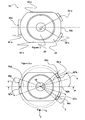
- the inner nozzle 12 comprises a metal casing 22, in which a refractory element 24 is cast which delimits the pouring channel 14, as shown in FIG. figure 1a .
- the metal casing 22 reinforces the refractory element 24, it is relatively thick, its walls having a thickness greater than 6 mm (millimeters).
- the metal casing delimits an internal nozzle plate, carrying a contact surface 26, shown in FIG. figure 1b , extending along a sliding plane parallel to the plane (X, Y).
- the contact surface 26 is intended to be in sealing contact with the sliding plate when the latter is slidably fed in the casting position, that is to say facing the inner nozzle 12, by the device 10.
- the surface sliding 26 is traversed by a pouring orifice 28, on which the casting channel 14 opens.
- the envelope 22, therefore the internal nozzle 12, comprises three flanges 30a, 30b, 30c for wedging the internal nozzle 12 against the frame 31 of the device 10, namely a first 30a, a second 30b and a third flange 30c.
- Each flange 30a, 30b, 30c has an upper surface 32a, 32b, 32c called said clamping surface, on which the clamping means 20 are intended to apply a clamping force, and a lower surface 34a, 34b, 34c said surface of support, intended to be in contact with the frame 31, in the example, the bearing surface extends in a substantially horizontal plane parallel to the plane (X, Y), called support plane.
- the clamping surfaces 32a, 32b, 32c are each arranged facing the bearing surfaces 34a, 34b, 34c, so that the clamping means 20 and the frame 31 sandwich the wedging edges 30a, 30b, 30c under the action of the clamping means 20.
- the wedging flanges 30a, 30b, 30c are distinct, i.e. they are separate, non-contiguous. More specifically in this example, the wedging flanges 30a, 30b, 30c protrude from a peripheral surface 36 of the plate of the inner nozzle 12, this surface 36 extending from the sliding surface 26 of the plate, preferably in a substantially vertical direction Z. Still in this example, the three wedging flanges 30a, 30b, 30c are made entirely of metal, that is to say that only metal between the bearing surfaces 34a, 34b, 34c and the clamping surfaces 32a, 32b, 32c.
- the inner nozzle 12 has two substantially longitudinal edges 40a, 40b and two substantially transverse edges 42a, 42b, namely a front transverse edge 42b and a rear transverse edge 42a. It further comprises a vertical central vertical plane P and the three wedging flanges 30a, 30b, 30c are arranged in Y on the periphery 36 of the nozzle 12, the base 44a of the Y being disposed in the central longitudinal plane P and the two branches 44b, 44c of Y being disposed on either side of this plane P.
- the second 30b and third 30c wedging flanges have a second 32b and a third 32c clamming surfaces, each of these second 32b and third 32c surfaces being disposed on either side of the longitudinal plane P.
- the second and third surfaces are arranged symmetrically.
- the surfaces 32b, 32c each have a center 32'b, 32'c positioned at an angle ⁇ (alpha) between 30 and 45 ° relative to the longitudinal plane P, with reference to the center 46 of the inner nozzle 12 , corresponding in the example to the center of the casting orifice 28.
- each of the second 32b and third 32c clamming surfaces is included in an angular sector ⁇ (beta) between 10 and 20 ° with reference to the center 46 of the inner nozzle 12.
- the first wedging flange 30a has a first clamping surface 32a passing through the longitudinal plane P of the nozzle 12. More specifically, the surface 32a extends substantially symmetrically with respect to the plane P, the center 32'a of this surface being positioned in the plane P.
- the surface 32a extends in a surface included in an angular sector ⁇ (gamma) between 14 and 52 ° with reference to the center 46 of the internal nozzle .
- the inner nozzle 12 further comprises gas injection means 48, the gas being injected into a groove in the contact surface of the inner nozzle, these means being disposed between the second 32b and the third 32c clamping surfaces.
- the means 48 comprise one or two channels opening onto a transverse vertical surface or transverse edge 49 forming part of the peripheral surface 36 and connecting the two wedging flanges 30b, 30c.
- the injected gas is, in this example, argon.
- the clamping means 20 comprise three clamping elements 50a, 50b, 50c, visible on the figure 2 , arranged at Y at the periphery of the inner nozzle 12, namely a first clamping element 50a at the base of the Y, disposed on the rear part of the central longitudinal plane P and a second 50b and a third 50c clamping elements, ends of the two branches of the Y, disposed on either side of the front portion of this plane P.
- the clamping means are arranged to exert their force on the transverse edges 42a, 42b of the inner nozzle .
- the clamping elements 50a, 50b, 50c have a configuration complementary to the configuration of the wedging flanges 30a, 30b, 30c. So, the first 50a, the second 50b and the third 50c clamping elements respectively exert a clamping force on the first 32a, second 32b and third 32c clamping surfaces described above.
- the clamping elements 50b, 50c are substantially identical. Only the structure of the element 50b will therefore be described, with reference to the Figures 2 and 2a .
- the clamping element 50b is rotatably mounted about an axis 52b fixed to the frame 31, extending substantially in the transverse direction Y or slightly inclined relative to this direction.
- the element 50b has a free end carrying a so-called clamping surface 54b intended to come into contact with the clamping surface 32b of the flange 30b, and to exert a clamping force on the surface 32b by pressing on this surface.
- the element 50b is actuated by a rotary member 56b (pivoting about a vertical axis) forming a cam in contact with the element 50b.
- the cam 56 when the cam 56 is rotated, it exerts a horizontal force on the free end of the element 50b, according to the arrow illustrated on the figure 2a , which has the effect of pivoting down the free end, so the surface 54b around the axis 52b.
- the downward pivoting of the surface 54b thus generates a clamping force on the surface 32b.
- the clamping element 50b does not exert only a downward clamping force, but also a horizontal force, intended to immobilize the rim 30b horizontally.
- Element 50a has a shape similar to that of element 50b shown in FIG. figure 2a , except that it extends over a larger area than the element 50b.
- the element 50a is rotatably mounted about an axis 52a fixed on the frame 31, extending in the transverse direction Y, and has a free end carrying a clamping surface 54a intended to come into contact with the clamping surface. 32a by pressing this surface.
- the element 50a is actuated differently from the element 50b, in particular by connecting rod-crank means.
- a rotary member 56a pivotally mounted about an axis in the example parallel to the Y direction and forming a cam in contact with a cylinder 58.
- the cylinder 58 can translate in the X direction.
- rod 60 forming a rod
- one end 62 is rotatably mounted on the cylinder 58
- the opposite end 64 is rotatably mounted around the free end of the clamping element 50a, the element 50a forming a crank.
- the cylinder 58 also constitutes a housing for a rod 66 biased by means 68 for biasing the clamping element 50a in the rest position, namely a compression spring.
- the clamping element 50a is movably mounted between a rest position and a clamping position, being actuated by the crank-rod system, as follows.
- the rest position is illustrated on the figure 5a .
- the movable member 56a is rotated about its axis, so that it moves the cylinder 58 in the horizontal direction illustrated by the arrow 70.
- the connecting rod 60 drives the element 50a in rotation about its axis 52a, as illustrated on the Figures 5b, 5c then 5d, so that the clamping surface 54a presses on the surface 32a and the element 50a takes its position of clamoring.
- the rod 66 abuts against the vertical wall of the flange 30a, which has the effect of compressing the spring 68 as illustrated in FIG. figure 5c then 5d. Thanks to this compression of the spring, the system can return to the rest position by simply rotating the cam member 56a. Indeed, when the element 50a is in the position of clamping, as illustrated on the figure 5d , the rotation of the member 56a allows the cylinder 58 to translate in the direction indicated by the arrow 72 under the action of the spring 68 which relaxes, and thus allows the clamping member to resume the position illustrated on the figure 5a .
- the device 10 further comprises, between the two clamping elements 50b, 50c, two gas injection channels for the nozzle 12, opening onto a vertical transverse surface 51 of the device 10.
- the injection channels of the device 10 are in the extension of the channels 48 of the nozzle 12, and the clamping position of the elements 50b, 50c ensures a particularly tight connection of these channels.
- the clamping method comprises a first step of abutment of the transverse vertical surface 49 of the nozzle 12, arranged between the clamping flanges. 30b, 30c, against the transverse vertical surface 51 of the frame 31 of the device 10, followed by an actuation of the first clamping element 50a in the clamping position.
- the first element 50a translates in accordance with the arrow 70 of the figure 5a , abuts against the flange 30a, which has the effect of pressing the inner nozzle 12 against the transverse edge 51 of the device before the device 10, so refer to it very precisely against this front edge.
- the setting of the clamping position by the clamping element 50a simultaneously generates the compression of seals arranged in the gas injection channels 48.
- the seals can be placed on the inner nozzle or on the device. They are preferably made of graphite.
- the translation along the arrow 70 allows a controlled compression of the joints.
- the clamping means exert their force on the transverse edges 42a, 42b of the inner nozzle, while the thrust means 18 exert their force on the longitudinal edges of the sliding plate, at the longitudinal edges 17a, 17b of the device 10. It comes out that pressure is exerted on substantially the entire circumference of the contact surface between the inner nozzle 12 and the sliding plate, resulting in a better seal.
Abstract
Description
La présente invention concerne le domaine technique de la coulée continue de métal de liquide. Elle concerne plus précisément le clamage d'une busette interne dans une installation de coulée continue.The present invention relates to the technical field of continuous casting of liquid metal. It relates more specifically to the clamming of an internal nozzle in a continuous casting installation.
Dans une installation de coulée, le métal liquide est généralement contenu dans un récipient métallurgique, par exemple un répartiteur, avant d'être transféré dans un autre conteneur, par exemple dans un moule de coulée. Le métal est transféré du récipient vers le conteneur grâce à une busette ménagée sur le fond du récipient métallurgique, appelée busette interne (« inner nozzle » en anglais), venant en contact étanche avec une plaque coulissante de transfert (ou plaque de coulée) amenée dans le prolongement de la busette interne grâce à un dispositif de maintien et de changement de plaque, rapporté sous le récipient métallurgique. Cette plaque coulissante peut être une plaque calibrée, un tube de coulée voire une cassette comprenant deux plaques ou plus. La plaque permet de transférer le métal liquide, soit sous forme de jet libre, soit en guidant le jet lorsque la plaque est une busette externe (« pouring nozzle » ou pouring submerged nozzle en anglais), comportant un tube de coulée.In a casting plant, the liquid metal is generally contained in a metallurgical vessel, for example a distributor, before being transferred to another container, for example in a casting mold. The metal is transferred from the container to the container by means of a nozzle formed on the bottom of the metallurgical vessel, called the inner nozzle ("inner nozzle" in English), coming into sealing contact with a sliding transfer plate (or casting plate) brought in the extension of the internal nozzle through a holding device and plate change, reported under the metallurgical vessel. This sliding plate may be a calibrated plate, a pouring tube or a cassette comprising two or more plates. The plate makes it possible to transfer the liquid metal, either in the form of a free jet or by guiding the jet when the plate is an external nozzle ("pouring nozzle" or pouring submerged nozzle in English), comprising a pouring tube.
Un exemple d'installation est décrit dans le document
Une difficulté réside dans le fait que l'étanchéité de la jonction busette interne / plaque coulissante doit être la plus parfaite possible, sans quoi du métal liquide s'incorpore entre les deux pièces, ce qui détériore les surfaces des éléments réfractaires lors du remplacement des plaques. De plus le manque d'étanchéité (de contact entre les deux éléments réfractaires) permet à l'air de s'infiltrer, ce qui est nocif aussi bien pour les éléments réfractaires que pour la qualité du métal coulé.One difficulty lies in the fact that the sealing of the inner nozzle junction / sliding plate must be as perfect as possible, otherwise liquid metal is incorporated between the two parts, which deteriorates the surfaces of the refractory elements when replacing the plates. Moreover the lack of sealing (contact between the two refractory elements) allows the air to infiltrate, which is harmful for both the refractory elements for the quality of the cast metal.
L'invention a notamment pour but d'augmenter le contact entre la plaque de la busette interne et la plaque coulissante. L'invention a également pour but d'optimiser la répartition des contraintes dans les éléments réfractaires.The invention particularly aims to increase the contact between the plate of the inner nozzle and the sliding plate. The invention also aims to optimize the distribution of stresses in the refractory elements.
A cet effet, l'invention a notamment pour objet un dispositif de maintien et de changement d'une plaque coulissante rapporté sous un récipient métallurgique pour le transfert de métal liquide contenu dans le récipient, permettant de guider la plaque coulissante vers une position de coulée dans laquelle elle prolonge un canal de coulée d'une busette interne ménagée sur le récipient métallurgique, la direction de changement de plaque correspondant à une direction longitudinale du dispositif, et la direction perpendiculaire à la direction de changement de plaque correspondant à une direction transversale du dispositif, la plaque coulissante et la busette interne présentant chacune deux bords sensiblement longitudinaux et deux bords sensiblement transversaux, le dispositif comprenant :
- des moyens de guidage de la plaque coulissante depuis une position d'attente vers une position de coulée,
- des moyens de poussée de la plaque en position de coulée contre la busette interne, ces moyens étant agencés pour exercer une force sur une surface inférieure de chacun des deux bords longitudinaux de la plaque coulissante, de manière à pousser la plaque en contact étanche contre la busette interne,
- des moyens de clamage de la busette interne, agencés pour exercer une force sur une surface supérieure de deux bords opposés de la busette interne, de façon à maintenir la busette interne en appui contre un bâti du dispositif,
- means for guiding the sliding plate from a waiting position to a casting position,
- means for thrusting the plate in a casting position against the inner nozzle, these means being arranged to exert a force on a lower surface of each of the two longitudinal edges of the sliding plate, so as to push the plate into sealing contact against the internal nozzle,
- means for clamping the inner nozzle, arranged to exert a force on an upper surface of two opposite edges of the inner nozzle, so as to keep the inner nozzle bearing against a frame of the device,
Ainsi, on propose d'exercer la force de clamage le long des bords transversaux de la busette interne, de telle sorte que l'on améliore l'étanchéité au niveau des bords transversaux du plan de contact busette interne / plaque coulissante, tout en conservant une force de poussée sur les bords longitudinaux de ce plan de contact. En d'autre termes, grâce aux moyens de clamage et aux moyens de poussée ainsi disposés, on peut exercer une force imposant le contact sur sensiblement toute la circonférence du plan de contact busette interne / plaque coulissante, d'où une meilleure étanchéité donc une plus grande durée de vie des pièces et une amélioration de la qualité du métal coulé. En particulier, les inventeurs ont constaté qu'il est plus intéressant d'exercer les forces de cette façon que lorsque la force de poussée et la force de clamage sont appliquées l'une en face de l'autre, comme cela est pratiqué dans l'état de la technique, du fait que la pression forte sur les bords longitudinaux de la busette interne et de la plaque coulissante peut générer un écartement des bords transversaux respectifs.Thus, it is proposed to exert the clamping force along the transverse edges of the inner nozzle, so that the sealing is improved at the transverse edges of the internal nozzle / sliding plate contact plane, while retaining a thrust force on the longitudinal edges of this contact plane. In other words, thanks to the clamping means and the thrust means thus arranged, it is possible to exert a force imposing the contact on substantially the entire circumference of the internal nozzle / slide plate contact plane, hence a better seal, therefore a longer life of parts and improved quality of cast metal. In particular, the inventors have found that it is more advantageous to exert forces in this way than when the thrust force and the clamping force are applied opposite each other, as is practiced in the state of the art, because the strong pressure on the longitudinal edges of the inner nozzle and the sliding plate can generate a spacing of the respective transverse edges.
Par ailleurs, les moyens de clamage ainsi positionnés dans la direction transversale peuvent en outre assurer une mise en référence de la busette interne par rapport au dispositif de maintien et de changement de plaque le long de la direction transversale, ce qui est particulièrement intéressant. En effet, la busette interne subit un certain nombre de tensions dans la direction longitudinale au cours des changements de plaque, si bien que les forces de clamage réparties dans la direction transversale permettent de caler la busette interne dans la direction longitudinale, et ainsi de l'immobiliser dans la direction longitudinale malgré les mouvements dus aux changements de plaque.Furthermore, the clamping means thus positioned in the transverse direction can further ensure a referencing of the inner nozzle relative to the holding device and plate change along the transverse direction, which is particularly interesting. Indeed, the internal nozzle undergoes a certain number of tensions in the longitudinal direction during the plate changes, so that the clamping forces distributed in the transverse direction can wedge the inner nozzle in the longitudinal direction, and thus the immobilize in the longitudinal direction despite the movements due to plate changes.
On entend par « moyens de clamage » (« clamping means » en anglais) des moyens de bridage de la busette interne, permettant d'exercer une pression sur la busette interne pour l'immobiliser par rapport au bâti sur lequel sont montés les moyens de clamage. Généralement, la force exercée par les moyens de clamage sur la busette interne est une force dirigée notamment vers le bas, appliquée sur une surface supérieure de la busette interne, et la force exercée par les moyens de poussée sur la plaque coulissante est une force dirigée notamment vers le haut, appliquée sur une surface inférieure de la plaque. On définit la direction verticale comme la direction d'écoulement du métal liquide à la sortie du récipient métallurgique. La direction transversale est définie comme la direction perpendiculaire aux deux autres directions verticale et longitudinale, de façon que les directions longitudinale, transversale et vertical définissent un repère orthogonal. Par ailleurs, on notera que la direction avant est définie en référence au sens de changement de plaque dans le dispositif de changement de plaque, la plaque étant déplacée de l'arrière vers l'avant pour prendre les positions successives suivantes : position d'attente (lorsqu'une autre plaque est déjà en position de coulée), position de coulée (lorsqu'un orifice de coulée ménagé sur la plaque prolonge le canal de coulée de la busette interne), position d'obturation (lorsque une surface d'obturation ménagée sur la plaque obture le canal de coulée) et position d'éjection (lorsque la face de glissement de la plaque est dégagée du récipient). On notera en outre que la busette interne et/ou la plaque coulissante sont généralement composées chacune d'une enveloppe métallique entourant un élément réfractaire. La plaque coulissante peut éventuellement comprendre une extension tubulaire. Cette extension tubulaire peut se prolonger suffisamment afin que l'extrémité de celle-ci soit immergée dans le récipient métallurgique situé en aval, par exemple le moule de coulée. On parlera, dans ce cas de busette externe. Le tube de coulée destiné à être immergé est réalisé en élément réfractaire.The term "clamping means" means clamping means of the inner nozzle, for exerting pressure on the inner nozzle to immobilize it relative to the frame on which are mounted the means of clamping. Generally, the force exerted by the clamping means on the inner nozzle is a force directed in particular downwards, applied on an upper surface of the inner nozzle, and the force exerted by the thrust means on the sliding plate is a directed force. especially upwards, applied to a lower surface of the plate. The vertical direction is defined as the direction of flow of the liquid metal at the outlet of the metallurgical vessel. The transverse direction is defined as the direction perpendicular to the other two vertical and longitudinal directions, so that the longitudinal, transverse and vertical directions define an orthogonal reference. Furthermore, it will be noted that the forward direction is defined with reference to the direction of change of plate in the plate changing device, the plate being moved from the rear to the front to take the following successive positions: waiting position (when another plate is already in the casting position), casting position (when a casting orifice on the plate extends the inner nozzle casting channel), shutter position (when a sealing surface formed on the plate closes the casting channel) and ejection position (when the sliding face of the plate is clear of the container). Note further that the inner nozzle and / or the sliding plate are generally each composed of a metal casing surrounding a refractory element. The sliding plate may optionally comprise a tubular extension. This tubular extension may extend sufficiently so that the end thereof is immersed in the metallurgical vessel downstream, for example the casting mold. We will speak, in this case of external nozzle. The pouring tube intended to be immersed is made of refractory element.
Le dispositif peut en outre comporter l'une ou plusieurs des caractéristiques suivantes, prises seules ou en combinaison.The device may further include one or more of the following features, taken alone or in combination.
Le dispositif comprend un plan longitudinal central vertical ayant une partie avant et une partie arrière, une plaque subissant un glissement depuis l'arrière vers l'avant du dispositif, et les moyens de clamage comprennent trois éléments de clamage disposés en Y à la périphérie de la busette interne, à savoir un premier élément de clamage à la base du Y, disposée sur la partie arrière du plan longitudinal central et un deuxième et un troisième éléments de clamage, aux extrémités des deux branches du Y, disposées de part et d'autre de la partie avant de ce plan. Cette disposition en Y des éléments de clamage permet d'assurer de façon particulièrement satisfaisante le clamage de la busette, tout en limitant l'encombrement du système de clamage et en nécessitant un procédé de clamage particulièrement simple. De préférence, les moyens de clamage comprennent trois et uniquement trois éléments de clamage. On notera que le plan correspond à un plan longitudinal vertical central, c'est-à-dire qu'il s'étend dans les directions longitudinale et verticale du dispositif et qu'il passe par le centre du dispositif, ce centre pouvant être défini par le centre de l'orifice de coulée de la busette interne.The device comprises a vertical central longitudinal plane having a front portion and a rear portion, a plate slidable from the rear to the front of the device, and the clamming means comprise three Y-shaped clamper elements at the periphery of the device. the internal nozzle, namely a first clamping element at the base of the Y, disposed on the rear part of the central longitudinal plane and a second and a third clamping element, at the ends of the two branches of the Y, arranged on the side and other of the front part of this plane. This Y-shaped arrangement of the clamping elements makes it possible to ensure, in a particularly satisfactory manner, the clamping of the nozzle, while limiting the bulk of the clamping system and by requiring a particularly simple clamping method. Preferably, the clamping means comprise three and only three clamping elements. It will be noted that the plane corresponds to a central vertical longitudinal plane, that is to say that it extends in the longitudinal and vertical directions of the device and that it passes through the center of the device, this center being able to be defined by the center of the casting orifice of the inner nozzle.
Le deuxième et le troisième éléments de clamage exercent une force de clamage sur des surfaces de la busette interne dites deuxième et troisième surfaces de clamage, chacune de ces deuxième et troisième surfaces étant disposée de part et d'autre du plan longitudinal et présentant un centre positionné à un angle compris entre 30 et 45° par rapport au plan longitudinal, en référence au centre de la busette interne.The second and third clamming elements exert a clamping force on surfaces of the inner nozzle called second and third clamming surfaces, each of these second and third surfaces being disposed on either side of the longitudinal plane and having a center positioned at an angle between 30 and 45 ° relative to the longitudinal plane, with reference to the center of the inner nozzle.
Les dites deuxième et troisième surfaces de clamage sont disposées de façon symétrique par rapport au plan longitudinal.The said second and third clamming surfaces are arranged symmetrically with respect to the longitudinal plane.
On notera que pour une busette interne symétrique, dans laquelle l'orifice de coulée est disposé au centre de la surface de glissement, le centre de la busette interne correspond au centre de l'orifice de coulée de la busette interne. Par ailleurs, pour une busette asymétrique, par exemple ayant une forme générale rectangulaire et dans laquelle le canal de coulée n'est pas disposé au centre de la surface de glissement, le centre de la busette interne correspond au centre de la surface de glissement de la busette, par exemple le centre (ou point d'intersection des médianes) du rectangle circonscrit à la busette, défini sans les trois surfaces de clamage.Note that for a symmetrical inner nozzle, in which the casting orifice is disposed in the center of the sliding surface, the center of the inner nozzle corresponds to the center of the casting orifice of the inner nozzle. Furthermore, for an asymmetrical nozzle, for example having a generally rectangular shape and in which the casting channel is not disposed in the center of the sliding surface, the center of the inner nozzle corresponds to the center of the sliding surface of the nozzle, for example the center (or point of intersection of the medians) of the rectangle circumscribed to the nozzle, defined without the three clamming surfaces.
Chacune des deuxième et troisième surfaces de clamage est inclue dans un secteur angulaire compris entre 10 et 20° en référence au centre de la busette interne.Each of the second and third clamming surfaces is included in an angular sector of between 10 and 20 ° with reference to the center of the inner nozzle.
Le premier élément de clamage exerce une force de clamage sur une surface de la busette interne dite première surface de clamage, cette surface passant par le plan longitudinal et s'étendant de façon sensiblement symétrique par rapport à ce plan, dans une surface inclue dans un secteur angulaire compris entre 14 et 52° en référence au centre de la busette interne.The first clamping element exerts a clamping force on a surface of the inner nozzle called said first clamping surface, this surface passing through the longitudinal plane and extending substantially symmetrically with respect to this plane, in a surface included in a angular sector between 14 and 52 ° with reference to the center of the inner nozzle.
Les moyens de clamage comprennent au moins un premier élément de clamage, venant en appui contre une surface de clamage de la busette interne, l'élément de clamage étant monté mobile entre une position de repos et une position de clamage, en étant actionné par des moyens formant bielle-manivelle. L'utilisation d'un système bielle-manivelle permet de simplifier le procédé de clamage, de limiter l'encombrement du système de clamage et d'augmenter la force de clamage. Ce système permet le déplacement de la busette jusqu'à venir en butée avec une surface de référence du bâti. La busette est ainsi immobilisée et n'est pas entrainée pendant le remplacement de la plaque mobile.The clamping means comprise at least one first clamping element, bearing against a clamping surface of the inner nozzle, the clamping member being movably mounted between a rest position and a clamping position, being actuated by means forming crank-handle. The use of a crank-crank system makes it possible to simplify the clamping process, to limit the size of the clamping system and to increase the clamping force. This system allows the displacement of the nozzle until it comes into abutment with a reference surface of the frame. The nozzle is thus immobilized and is not driven during the replacement of the movable plate.
Le dispositif comprend au moins un canal d'injection de gaz dans le canal de coulée de la busette interne, ce canal étant disposé entre le deuxième et le troisième élément de clamage. Ainsi, le passage en position de clamage par le premier élément de clamage peut comprimer automatiquement un joint pour l'injection de gaz.The device comprises at least one gas injection channel in the casting channel of the inner nozzle, this channel being disposed between the second and the third clamping element. Thus, the passage in the clamping position by the first clamping element can automatically compress a seal for gas injection.
L'invention a également pour objet un ensemble d'une busette interne et d'un dispositif de maintien et de changement de plaque tel que décrit ci-dessus, ainsi qu'un ensemble d'une busette interne et d'un système de clamage comportant les premier, deuxième et troisième éléments de clamage du dispositif décrit ci-dessus.The invention also relates to a set of an internal nozzle and a holding device and plate change as described above, and a set of an internal nozzle and a clamping system comprising the first, second and third clamming elements of the device described above.
L'invention a par ailleurs pour objet une busette interne pour un récipient métallurgique pour le transfert de métal liquide contenu dans le récipient, la direction de coulée définissant une direction verticale, la busette interne comprenant une plaque de busette interne comprenant une surface dite de contact, s'étendant selon un plan sensiblement horizontal, appelé plan de glissement, destinée à être en contact étanche avec une plaque coulissante amenée par glissement en regard de la busette interne par un dispositif de maintien et de changement de plaque, caractérisée en ce que la plaque de la busette interne comprend trois rebords distincts de calage de la busette interne contre un bâti ménagé sur le dispositif de maintien et de changement de plaque, les trois rebords faisant saillie d'une surface périphérique de la plaque de la busette.The invention furthermore relates to an internal nozzle for a metallurgical container for the transfer of liquid metal contained in the container, the casting direction defining a vertical direction, the internal nozzle comprising an internal nozzle plate comprising a so-called contact surface. , extending in a substantially horizontal plane, called sliding plane, intended to be in sealing contact with a sliding plate slidably brought opposite the internal nozzle by a holding and plate changing device, characterized in that the Inner nozzle plate has three separate internal nozzle clamping flanges against a frame on the plate holding and changing device, the three flanges protruding from a peripheral surface of the nozzle plate.
On entend par « surface périphérique » la surface s'étendant depuis la surface de glissement de la plaque, de préférence dans une direction sensiblement verticale."Peripheral surface" means the surface extending from the sliding surface of the plate, preferably in a substantially vertical direction.
On entend par « rebords distincts » des rebords séparés, non contigus."Separate edges" means separate, non-contiguous ledges.
La busette interne peut en outre comporter l'une ou plusieurs des caractéristiques suivantes, prises seules ou en combinaison. Des avantages de ces caractéristiques ont été développés précédemment.The inner nozzle may further include one or more of the following features, taken alone or in combination. Advantages of these features have been developed previously.
Chaque rebord de calage présente une surface dite d'appui destinée à être en contact avec le bâti, s'étendant selon un plan sensiblement horizontal, appelé plan d'appui, et une surface dite de clamage sur laquelle un système de clamage est destiné à appliquer une force de clamage.Each wedging flange has a so-called bearing surface intended to be in contact with the frame, extending in a substantially horizontal plane, called the support plane, and a so-called clamming surface on which a clamming system is intended to apply a clamming force.
La surface dite de clamage est disposée en regard de la surface d'appui de façon que le système de clamage et le bâti prennent en sandwich le rebord de calage sous l'action du système de clamage.The so-called clamming surface is arranged facing the bearing surface so that the clamping system and the frame sandwich the wedge flange under the action of the clamping system.
Préférentiellement, le rebord de calage est intégralement réalisé en métal. Les surfaces d'appui ou les surfaces de clamage sont planes. De façon alternative, les surfaces peuvent présenter différentes formes, par exemple, inclinées, bombées ou rainurées. Préférentiellement, les surfaces s'étendent dans un plan sensiblement horizontal. Il est important qu'elles puissent remplir leurs rôles de surfaces d'appui ou de surfaces de clamage. De même, un élément tel que de la fibre, un joint ou un élément compressible pourrait être associé (ajouté, collé ou juxtaposé) à la surface d'appui ou de clamage. Les avantages liés à la présente invention sont conservés.Preferably, the wedge flange is made entirely of metal. The bearing surfaces or the clamping surfaces are flat. Alternatively, the surfaces may have different shapes, for example, inclined, curved or grooved. Preferably, the surfaces extend in a substantially horizontal plane. It is important that they can fulfill their roles as support surfaces or as clamming surfaces. Similarly, an element such as fiber, a seal or a compressible element could be associated (added, glued or juxtaposed) to the support or clamming surface. The advantages of the present invention are retained.
La busette interne comprend un plan longitudinal central vertical, dans laquelle les trois rebords de calage sont disposés en Y sur la périphérie de la busette, la base du Y étant disposée dans le plan longitudinal central et les deux branches du Y étant disposées de part et d'autre de ce plan.The inner nozzle comprises a vertical central longitudinal plane, in which the three wedging flanges are arranged in Y on the periphery of the nozzle, the base of the Y being disposed in the central longitudinal plane and the two branches of the Y being arranged on the outside. else of this plan.
Les deuxième et troisième rebords de calage présentent une deuxième et une troisième surfaces de clamage, chacune de ces deuxième et troisième surfaces étant disposée de part et d'autre du plan longitudinal et présentant un centre positionné à un angle compris entre 30 et 45° par rapport au plan longitudinal, en référence au centre de la busette interne.The second and third chock flanges have a second and a third clamming surfaces, each of these second and third surfaces being disposed on either side of the longitudinal plane and having a center positioned at an angle of between 30 and 45 ° with respect to the longitudinal plane, with reference to the center of the internal nozzle .
Les dites deuxième et troisième surfaces de clamage de la busette sont disposées de façon symétrique par rapport au plan longitudinal.The said second and third clamming surfaces of the nozzle are arranged symmetrically with respect to the longitudinal plane.
Le premier rebord de clamage présente une première surface de clamage, cette surface passant par le plan longitudinal de la busette et s'étendant de façon sensiblement symétrique par rapport à ce plan, dans une surface inclue dans un secteur angulaire compris entre 14 et 52° en référence au centre de la busette interne.The first clamping flange has a first clamping surface, this surface passing through the longitudinal plane of the nozzle and extending substantially symmetrically with respect to this plane, in a surface included in an angular sector of between 14 and 52.degree. referring to the center of the internal nozzle.
La busette interne comprend des moyens d'injection de gaz dans le canal de coulée de la busette interne, ces moyens étant disposés entre la deuxième et la troisième surface de clamage.The internal nozzle comprises gas injection means in the casting channel of the inner nozzle, these means being arranged between the second and the third clamping surface.
L'invention a également pour objet une enveloppe métallique pour une busette interne telle que décrite ci-dessus. La busette est disposée sur un récipient métallurgique pour le transfert de métal liquide contenu dans le récipient, la direction de coulée définissant une direction verticale, la busette interne comprenant une plaque de busette interne comprenant une surface dite de contact, s'étendant selon un plan sensiblement horizontal, appelé plan de glissement, destinée à être en contact étanche avec une plaque coulissante amenée par glissement en regard de la busette interne par un dispositif de maintien et de changement de plaque. L'enveloppe métallique de la busette interne est caractérisée en ce qu'elle comprend trois rebords distincts pour le calage de la busette interne contre un bâti ménagé sur le dispositif de maintien et de changement de plaque. De préférence, chaque rebord de calage présente une surface dite d'appui destinée à être en contact avec le bâti, s'étendant selon un plan sensiblement horizontal, appelé plan d'appui, et une surface dite de clamage sur laquelle un système de clamage est destiné à appliquer une force de clamage. De préférence, la surface dite de clamage est disposée en regard de la surface d'appui de façon que le système de clamage et le bâti prennent en sandwich le rebord de calage sous l'action du système de clamage.The invention also relates to a metal casing for an inner nozzle as described above. The nozzle is disposed on a metallurgical vessel for the transfer of liquid metal contained in the vessel, the casting direction defining a vertical direction, the inner nozzle comprising an inner nozzle plate comprising a so-called contact surface, extending in a plane substantially horizontal, called sliding plane, intended to be in sealing contact with a sliding plate slidably fed opposite the inner nozzle by a holding device and plate change. The metal casing of the inner nozzle is characterized in that it comprises three distinct edges for the setting of the inner nozzle against a frame formed on the holding device and plate change. Preferably, each wedging flange has a so-called bearing surface intended to be in contact with the frame, extending in a substantially horizontal plane, called the support plane, and a so-called clamming surface on which a clamming system is intended to apply a clamming force. Preferably, the so-called clamming surface is disposed facing the bearing surface so that the clamping system and the frame sandwich the wedging flange under the action of the clamping system.
De préférence, l'enveloppe présente des parois ayant une épaisseur supérieure à 6 mm. On facilite ainsi la coulabilité de l'enveloppe, par exemple en fonte lamellaire, au cours de la fabrication.Preferably, the envelope has walls having a thickness greater than 6 mm. This facilitates the flowability of the envelope, for example cast iron, during manufacture.
De préférence, chaque rebord de clamage est intégralement réalisé en métal. En d'autres termes, les rebords métalliques sont pleins, c'est-à-dire qu'il n'y a que du métal entre la surface d'appui et la surface de clamage, si bien que seul du métal est mis sous contrainte lors du clamage, ce qui épargne le matériau réfractaire de la busette interne.Preferably, each clamming flange is made entirely of metal. In other words, the metal flanges are solid, that is to say that there is only metal between the bearing surface and the clamping surface, so that only metal is put under stress during clamping, which spares the refractory material of the internal nozzle.
L'invention a par ailleurs pour objet un procédé d'assemblage d'une enveloppe métallique telle que décrite ci-dessus et d'un élément réfractaire pour fabriquer une busette interne.The invention also relates to a method of assembling a metal casing as described above and a refractory element for making a nozzle internal.
L'invention a enfin pour objet un procédé de clamage d'une busette interne dans un dispositif tel que décrit ci-dessus, comprenant une première étape de mise en butée du bord transversal avant de la busette, suivie d'un actionnement du premier élément de clamage en position de clamage, ce premier élément étant disposé contre le bord transversal arrière de la busette interne, puis d'un actionnement d'un deuxième et d'un troisième éléments de clamage, chacun des deuxième et troisième éléments étant disposé contre le bord transversal avant de la busette interne.The invention finally relates to a method of clamping an internal nozzle in a device as described above, comprising a first step of abutment of the front transverse edge of the nozzle, followed by actuation of the first element clamming position, this first element being arranged against the rear transverse edge of the inner nozzle, then an actuation of a second and a third clamping elements, each of the second and third elements being arranged against the front transverse edge of the inner nozzle.
De préférence, l'établissement de la position de clamage par le premier élément de clamage génère simultanément la compression d'un joint pour l'injection de gaz dans la busette interne.Preferably, the establishment of the clamping position by the first clamping member simultaneously generates the compression of a seal for injecting gas into the inner nozzle.
L'invention sera mieux comprise à la lecture de la description qui va suivre, donnée uniquement à titre d'exemple non limitatif de la portée de l'invention et faite en se référant aux dessins, dans lesquels :
- la
figure 1a est une vue en perspective de dessus d'une busette interne selon un mode de réalisation ; - la
figure 1b est une vue en perspective de dessus de la busette de lafigure 1 lorsqu'elle est retournée dans la direction verticale ; - la
figure 2 est une vue en perspective de dessus de la busette de lafigure 1 dans une partie d'un dispositif de maintien et de changement de plaque ; - la
figure 2a est une vue en coupe illustrant la structure d'un élément de clamage de lafigure 2 ; - les
figures 3 et 3a sont des vues de dessus de la busette de lafigure 1 ; - la
figure 4 est une vue en coupe de moyens de clamage de la busette de lafigure 1 ; et - les
figures 5 et5a à 5d sont des vues en coupe selon un plan longitudinal illustrant le fonctionnement des moyens de clamage de lafigure 4 .
- the
figure 1a is a perspective view from above of an internal nozzle according to one embodiment; - the
figure 1b is a perspective view from above of the nozzle of thefigure 1 when returned in the vertical direction; - the
figure 2 is a perspective view from above of the nozzle of thefigure 1 in a portion of a holding and plate changing device; - the
figure 2a is a sectional view illustrating the structure of a clamming element of thefigure 2 ; - the
Figures 3 and 3a are top views of the nozzle of thefigure 1 ; - the
figure 4 is a sectional view of the clamming means of the nozzle of thefigure 1 ; and - the
figures 5 and5a to 5d are sectional views along a longitudinal plane illustrating the operation of the clamming means of thefigure 4 .
Dans la suite, la direction verticale correspondant à la direction de coulée est indiquée comme la direction Z, la direction longitudinale correspondant à la direction de changement de la plaque est indiquée comme la direction X, et la direction transversale est indiquée comme la direction Y. Les directions X, Y, Z sont orthogonales les unes aux autres.In the following, the vertical direction corresponding to the direction of casting is indicated as the direction Z, the longitudinal direction corresponding to the direction of change of the plate is indicated as the direction X, and the transverse direction is indicated as the direction Y. The X, Y, Z directions are orthogonal to each other.
Dans une installation de coulée continue de métal liquide, par exemple d'acier liquide, un dispositif 10 de maintien et de changement de plaque coulissante permet de transférer le métal contenu dans un récipient métallurgique, par exemple un répartiteur, vers un conteneur, tel qu'un ou plusieurs moules de coulée. Le dispositif 10, représenté notamment sur la
La busette interne 12 comprend une enveloppe métallique 22, dans laquelle est coulé un élément réfractaire 24 délimitant le canal de coulée 14, comme représenté sur la
Les rebords de calage 30a, 30b, 30c sont distincts, c'est-à-dire qu'ils sont séparés, non contigus. Plus précisément dans cet exemple, les rebords de calage 30a, 30b, 30c font saillie d'une surface périphérique 36 de la plaque de la busette interne 12, cette surface 36 s'étendant depuis la surface de glissement 26 de la plaque, de préférence dans une direction sensiblement verticale Z. Toujours dans cet exemple, les trois rebords de calage 30a, 30b, 30c sont intégralement réalisés en métal, c'est-à-dire qu'il n'y a que du métal entre les surfaces d'appui 34a, 34b, 34c et les surfaces de clamage 32a, 32b, 32c.The wedging
Comme on peut le voir sur la
La busette interne 12 comporte en outre des moyens 48 d'injection de gaz, le gaz pouvant être injecté dans une rainure de la surface de contact de la busette interne, ces moyens 48 étant disposés entre la deuxième 32b et la troisième 32c surfaces de clamage. En l'occurrence, les moyens 48 comprennent un ou deux canaux débouchant sur une surface verticale transversale ou bord transversal 49 faisant partie de la surface périphérique 36 et reliant les deux rebords de calage 30b, 30c. Le gaz injecté est, dans cet exemple, de l'argon.The
Les moyens de clamage 20 comprennent trois éléments de clamage 50a, 50b, 50c, visibles sur la
Les éléments de clamage 50b, 50c sont sensiblement identiques. Seule la structure de l'élément 50b va donc être décrite, en référence aux
La structure de l'élément de clamage 50a va à présent être décrite, en référence aux
L'élément de clamage 50a est monté mobile entre une position de repos et une position de clamage, en étant actionné par le système bielle-manivelle, de la façon suivante. La position de repos est illustrée sur la
Le dispositif 10 comporte par ailleurs, entre les deux éléments de clamage 50b, 50c, deux canaux d'injection de gaz pour la busette 12, débouchant sur une surface transversale verticale 51 du dispositif 10. Ainsi, lorsque l'élément 50a est en position de clamage, les canaux d'injection du dispositif 10 se trouvent dans le prolongement des canaux 48 de la busette 12, et la position de clamage des éléments 50b, 50c assure une jonction particulièrement étanche de ces canaux.The device 10 further comprises, between the two clamping
Le procédé de clamage de la busette interne 12 dans le dispositif 10 va à présent être décrit.The method of clamping the
Au début du procédé de clamage, la busette 12 est simplement placée dans le bâti 31 du dispositif 10. Le procédé de clamage comprend une première étape de mise en butée de la surface verticale transversale 49 de la busette 12, disposé entre les rebords de clamage 30b, 30c, contre la surface verticale transversale 51 du bâti 31 du dispositif 10, suivie d'un actionnement du premier élément de clamage 50a en position de clamage. Ainsi, le premier élément 50a effectue une translation conformément à la flèche 70 de la
Parmi les avantages de la busette 12 et du dispositif 10 décrits ci-dessus, on notera que les moyens de clamage exercent leur force sur les bords transversaux 42a, 42b de la busette interne, alors que les moyens de poussée 18 exercent leur force sur les bords longitudinaux de la plaque coulissante, au niveau des bords longitudinaux 17a, 17b du dispositif 10. Il en ressort que l'on exerce une pression sur sensiblement toute la circonférence de la surface de contact entre la busette interne 12 et la plaque coulissante, d'où une meilleure étanchéité.Among the advantages of the
On notera que l'invention n'est pas limitée aux modes de réalisation précédemment décrits.Note that the invention is not limited to the previously described embodiments.
En particulier, au cours du procédé d'assemblage de l'enveloppe 22 et de l'élément réfractaire 24 pour fabriquer la busette interne 12, on peut prévoir d'utiliser une enveloppe métallique 22 déjà utilisée et lui associer un nouvel élément réfractaire 24. Un élément réfractaire recyclé selon les méthodes connues de l'homme du métier peut également être utilisé.
- 10.
- dispositif de maintien et de changement de plaque ;
- 12.
- busette interne ;
- 14.
- canal de coulée ;
- 16.
- moyens de guidage ;
- 17a, 17b
- bords longitudinaux du dispositif ;
- 18.
- moyens de poussée ;
- 20.
- moyens de clamage ;
- 22.
- enveloppe métallique ;
- 24.
- élément réfractaire ;
- 26.
- surface de contact ;
- 28.
- orifice de coulée ;
- 30a, 30b, 30c
- rebords de calage ;
- 31.
- bâti ;
- 32a, 32b, 32c
- surface de clamage du rebord ;
- 34a, 34b, 34c
- surface d'appui ;
- 36.
- surface périphérique ;
- 40a, 40b
- bords longitudinaux de la busette ;
- 42a, 42b
- bords transversaux de la busette ;
- 44a
- Base de Y ;
- 44b, 44c
- branches du Y ;
- 46.
- centre de la busette interne ;
- 48.
- moyens d'injection de gaz ;
- 49.
- surface verticale transversale de la busette ;
- 50a, 50b, 50c
- éléments de clamage ;
- 51.
- surface verticale transversale du dispositif ;
- 52a, 52b
- axe d'élément de clamage ;
- 54b
- surface de clamage de l'élément de clamage ;
- 56a, 56b, 56c
- organe rotatif ou came ;
- 58.
- cylindre ;
- 60.
- tige formant bielle ;
- 66.
- Tige ;
- 68.
- moyens de rappel ;
- 70.
- Direction horizontale ;
- 72.
- Direction opposée à la
direction 70.
- 10.
- holding and plate changing device;
- 12.
- internal nozzle;
- 14.
- casting channel;
- 16.
- guide means;
- 17a, 17b
- longitudinal edges of the device;
- 18.
- pushing means;
- 20.
- clamming means;
- 22.
- metal casing;
- 24.
- refractory element;
- 26.
- contact surface ;
- 28.
- pouring orifice;
- 30a, 30b, 30c
- wedging edges;
- 31.
- built;
- 32a, 32b, 32c
- clamming surface of the rim;
- 34a, 34b, 34c
- bearing surface ;
- 36.
- peripheral surface;
- 40a, 40b
- longitudinal edges of the nozzle;
- 42a, 42b
- transverse edges of the nozzle;
- 44a
- Y base;
- 44b, 44c
- branches of the Y;
- 46.
- center of the internal nozzle;
- 48.
- gas injection means;
- 49.
- transverse vertical surface of the nozzle;
- 50a, 50b, 50c
- clamming elements;
- 51.
- transverse vertical surface of the device;
- 52a, 52b
- clamming element axis;
- 54b
- clamming surface of the clamming element;
- 56a, 56b, 56c
- rotating member or cam;
- 58.
- cylinder;
- 60.
- connecting rod;
- 66.
- Stem;
- 68.
- recall means;
- 70.
- Horizontal direction;
- 72.
- Direction Opposite
Management 70.
Claims (20)
caractérisé en ce que les moyens de clamage (50a, 50b, 50c) sont agencés pour exercer leur force sur les bords transversaux de la busette interne (12).
characterized in that the clamping means (50a, 50b, 50c) are arranged to exert their force on the transverse edges of the inner nozzle (12).
Priority Applications (28)
| Application Number | Priority Date | Filing Date | Title |
|---|---|---|---|
| EP10157126A EP2386368A1 (en) | 2010-03-19 | 2010-03-19 | Internal nozzle for transferring liquid metal contained in a container, system for clamping said nozzle and pouring device |
| BR112012022127-2A BR112012022127B1 (en) | 2010-03-19 | 2011-03-17 | PIPE EXCHANGE DEVICE FOR CONTAINING AND REPLACING AN INTERCHANGEABLE LEAK VALVE, INTERNAL VALVE MADE FROM REFRESHING METAL MATERIAL FROM A METAL PURPOSE, AND INTERNAL PIPE VALVE SET METAL COATING TO COATE AN INTERNAL VALVE |
| US13/635,788 US9221098B2 (en) | 2010-03-19 | 2011-03-17 | Inner nozzle for transferring molten metal contained in a vessel, system for clamping said nozzle and casting device |
| NZ602093A NZ602093A (en) | 2010-03-19 | 2011-03-17 | Inner nozzle for transferring molten metal contained in a vessel, system for clamping said nozzle and casting device |
| PL11709880T PL2547475T3 (en) | 2010-03-19 | 2011-03-17 | Inner nozzle for transferring molten metal in a vessel, system for clamping said nozzle and casting device. |
| KR1020127026587A KR101790810B1 (en) | 2010-03-19 | 2011-03-17 | Inner nozzle for transferring molten metal contained in a vessel, system for clamping said nozzle and casting device |
| RU2012136887/02A RU2593557C2 (en) | 2010-03-19 | 2011-03-17 | Device for replacement of pipes and inner nozzle for pouring of molten metal |
| CU2012000134A CU24101B1 (en) | 2010-03-19 | 2011-03-17 | TUBE EXCHANGE, INTERNAL NOZZLE AND METAL HOUSING DEVICE FOR COVERING AN INTERNAL NOZZLE FOR MOLDING METAL CAST OUT OF A CONTAINER. |
| PCT/EP2011/001326 WO2011113599A1 (en) | 2010-03-19 | 2011-03-17 | Inner nozzle for transferring molten metal contained in a vessel, system for clamping said nozzle and casting device |
| EP11709880.6A EP2547475B1 (en) | 2010-03-19 | 2011-03-17 | Inner nozzle for transferring molten metal in a vessel, system for clamping said nozzle and casting device. |
| MA35299A MA34152B1 (en) | 2010-03-19 | 2011-03-17 | INTERNAL NOZZLE FOR TRANSFERRING MELT METAL CONTAINED IN CONTAINER, CLAMPING SYSTEM FOR SAID NOZZLE, AND CASTING DEVICE |
| ES11709880.6T ES2563803T3 (en) | 2010-03-19 | 2011-03-17 | Internal bushing for transferring molten metal contained in a container, system for fixing said bushing and casting device |
| CA2790274A CA2790274C (en) | 2010-03-19 | 2011-03-17 | Inner nozzle for transferring molten metal contained in a vessel, system for clamping said nozzle and casting device. |
| MYPI2012003887A MY156535A (en) | 2010-03-19 | 2011-03-17 | Inner nozzle for transferring molten metal contained in a vessel, system for clamping said nozzle and casting device |
| MX2012010802A MX344894B (en) | 2010-03-19 | 2011-03-17 | Inner nozzle for transferring molten metal contained in a vessel, system for clamping said nozzle and casting device. |
| RS20160015A RS54491B1 (en) | 2010-03-19 | 2011-03-17 | Inner nozzle for transferring molten metal in a vessel, system for clamping said nozzle and casting device. |
| UAA201210223A UA108633C2 (en) | 2010-03-19 | 2011-03-17 | Internal nozzle for the transfer of molten metal contained in a tank, a system for pressing the specified nozzle to the foundry device |
| AU2011229489A AU2011229489B2 (en) | 2010-03-19 | 2011-03-17 | Inner nozzle for transferring molten metal contained in a vessel, system for clamping said nozzle and casting device |
| JP2013500370A JP5902666B2 (en) | 2010-03-19 | 2011-03-17 | Internal nozzle for pouring molten metal contained in container, clamping system for said nozzle, and casting apparatus |
| SI201130694T SI2547475T1 (en) | 2010-03-19 | 2011-03-17 | Inner nozzle for transferring molten metal in a vessel, system for clamping said nozzle and casting device. |
| ARP110100903A AR080696A1 (en) | 2010-03-19 | 2011-03-18 | TUBE EXCHANGE DEVICE, INTERNAL NOZZLE TO TRANSFER FUSED METAL CONTAINED IN A CONTAINER AND METAL HOUSING TO COVER SUCH NOZZLE. |
| TW100109323A TWI527642B (en) | 2010-03-19 | 2011-03-18 | Tube exchange device,inner nozzle,assembly of inner nozzle and tube exchange device and metallic casing |
| CN201110067945.1A CN102189233B (en) | 2010-03-19 | 2011-03-21 | Inner nozzle for transferring molten metal contained in a vessel, system for clamping said nozzle and casting device |
| CN2011200758641U CN202087822U (en) | 2010-03-19 | 2011-03-21 | Pouring nozzle exchanging device |
| CL2012002395A CL2012002395A1 (en) | 2010-03-19 | 2012-08-30 | Tube exchange device for holding and replacing an exchangeable pouring nozzle because it serves to mold molten metal out of a container, means for receiving and holding, means for moving and pressure; internal nozzle; assembly and metal housing. |
| EG2012091571A EG26994A (en) | 2010-03-19 | 2012-09-12 | Inner nozzle for transferring molten metal contained in a vessel, system for clamping said nozzle and casting device |
| US14/943,761 US9808863B2 (en) | 2010-03-19 | 2015-11-17 | Tube exchange device for holding and replacing a pouring nozzle, and assembly of a tube exchange device and a pouring nozzle |
| HRP20160219T HRP20160219T1 (en) | 2010-03-19 | 2016-03-01 | Inner nozzle for transferring molten metal contained in a vessel, system for clamping said nozzle and casting device |
Applications Claiming Priority (1)
| Application Number | Priority Date | Filing Date | Title |
|---|---|---|---|
| EP10157126A EP2386368A1 (en) | 2010-03-19 | 2010-03-19 | Internal nozzle for transferring liquid metal contained in a container, system for clamping said nozzle and pouring device |
Publications (1)
| Publication Number | Publication Date |
|---|---|
| EP2386368A1 true EP2386368A1 (en) | 2011-11-16 |
Family
ID=42340611
Family Applications (2)
| Application Number | Title | Priority Date | Filing Date |
|---|---|---|---|
| EP10157126A Withdrawn EP2386368A1 (en) | 2010-03-19 | 2010-03-19 | Internal nozzle for transferring liquid metal contained in a container, system for clamping said nozzle and pouring device |
| EP11709880.6A Active EP2547475B1 (en) | 2010-03-19 | 2011-03-17 | Inner nozzle for transferring molten metal in a vessel, system for clamping said nozzle and casting device. |
Family Applications After (1)
| Application Number | Title | Priority Date | Filing Date |
|---|---|---|---|
| EP11709880.6A Active EP2547475B1 (en) | 2010-03-19 | 2011-03-17 | Inner nozzle for transferring molten metal in a vessel, system for clamping said nozzle and casting device. |
Country Status (25)
| Country | Link |
|---|---|
| US (2) | US9221098B2 (en) |
| EP (2) | EP2386368A1 (en) |
| JP (1) | JP5902666B2 (en) |
| KR (1) | KR101790810B1 (en) |
| CN (2) | CN102189233B (en) |
| AR (1) | AR080696A1 (en) |
| AU (1) | AU2011229489B2 (en) |
| BR (1) | BR112012022127B1 (en) |
| CA (1) | CA2790274C (en) |
| CL (1) | CL2012002395A1 (en) |
| CU (1) | CU24101B1 (en) |
| EG (1) | EG26994A (en) |
| ES (1) | ES2563803T3 (en) |
| HR (1) | HRP20160219T1 (en) |
| MA (1) | MA34152B1 (en) |
| MX (1) | MX344894B (en) |
| MY (1) | MY156535A (en) |
| NZ (1) | NZ602093A (en) |
| PL (1) | PL2547475T3 (en) |
| RS (1) | RS54491B1 (en) |
| RU (1) | RU2593557C2 (en) |
| SI (1) | SI2547475T1 (en) |
| TW (1) | TWI527642B (en) |
| UA (1) | UA108633C2 (en) |
| WO (1) | WO2011113599A1 (en) |
Families Citing this family (8)
| Publication number | Priority date | Publication date | Assignee | Title |
|---|---|---|---|---|
| EP2386368A1 (en) * | 2010-03-19 | 2011-11-16 | Vesuvius Group S.A | Internal nozzle for transferring liquid metal contained in a container, system for clamping said nozzle and pouring device |
| AR086749A1 (en) * | 2011-06-28 | 2014-01-22 | Vesuvius Group Sa | CUTTING, ARTESA AND BUZA DE COLADA GATE DEVICE |
| TWI647029B (en) * | 2014-02-19 | 2019-01-11 | 比利時商維蘇威集團股份有限公司 | Ladle shroud for casting metal, kit of parts for coupling assembly for coupling said ladle shroud to a ladle, metal casting installation and coupling process |
| USD781940S1 (en) * | 2015-01-28 | 2017-03-21 | Krosaki Harima Corporation | Sliding nozzle plate |
| CN106493346B (en) * | 2016-12-12 | 2019-09-13 | 华耐国际(宜兴)高级陶瓷有限公司 | A kind of immersion water gap for continuously casting |
| CN109877307B (en) | 2017-11-10 | 2021-11-02 | 维苏威集团有限公司 | Self-locking type inner pipe orifice system |
| CN112317713B (en) * | 2020-11-04 | 2022-10-18 | 中冶赛迪信息技术(重庆)有限公司 | Continuous casting control method and system |
| CN113102740B (en) * | 2021-04-13 | 2021-11-02 | 广州立中锦山合金有限公司 | Liftable flow guide device for aluminum liquid transfer and use method thereof |
Citations (4)
| Publication number | Priority date | Publication date | Assignee | Title |
|---|---|---|---|---|
| EP0441927B1 (en) * | 1989-08-30 | 1994-12-14 | International Industrial Engineering S.A. | Sealable casting device for a metallurgical container |
| EP1289696A1 (en) | 2000-04-21 | 2003-03-12 | Vesuvius Crucible Company | One-piece inner nozzle and clamping device for holding such a nozzle |
| EP1439016A1 (en) * | 2003-01-20 | 2004-07-21 | Vesuvius Group S.A | Casting tube, clamping device for a casting tube and casting machine |
| DE202005017531U1 (en) * | 2005-11-09 | 2006-02-16 | Knöllinger FLO-TEC GmbH | Ladle slide comprising housing, head plate fixed on assembly plate and sliding plate located in sliding frame and moveable relative to hard plate useful in blast furnace industry for steel production |
Family Cites Families (18)
| Publication number | Priority date | Publication date | Assignee | Title |
|---|---|---|---|---|
| GB1472532A (en) * | 1973-04-27 | 1977-05-04 | Didier Werke Ag | Sliding gate nozzles for metallurgical vessels |
| DE2821839B2 (en) * | 1978-05-19 | 1981-04-16 | Stopine AG, Zug | Slide closure for the pouring of molten metal containing containers |
| EP0122904A3 (en) | 1983-03-21 | 1987-11-19 | Vesuvius International Corporation | Slide gate nozzle device for a vessel for the iron and steel or metallurgical industry |
| CA1251642A (en) * | 1983-11-02 | 1989-03-28 | Kazumi Arakawa | Molten metal discharging device |
| US5044533A (en) | 1990-10-01 | 1991-09-03 | Flo-Con Systems, Inc. | Clamp for bandless refractory and method |
| WO1992000821A1 (en) * | 1990-07-04 | 1992-01-23 | International Industrial Engineering S.A. | Improved pouring tube insertion and replacement device |
| US5211857A (en) | 1990-10-31 | 1993-05-18 | Leco Corporation | Gate safety arrangement |
| DE9408700U1 (en) | 1993-07-06 | 1994-09-08 | Stopinc Ag | Device for connecting and changing a pouring tube to a vessel containing molten metal |
| BE1007317A3 (en) * | 1993-07-27 | 1995-05-16 | Int Ind Eng Sa | Feed device and exchange tube casting in a continuous casting plant a thin slabs. |
| JP3322461B2 (en) | 1993-10-26 | 2002-09-09 | 黒崎播磨株式会社 | Plate brick detaching device for sliding nozzle device |
| FR2740368B1 (en) * | 1995-10-27 | 1997-12-12 | Vesuvius France Sa | METHOD FOR REUSING DRAWER CLOSURE PLATES AND PLATE FOR SAID CLOSURE |
| CN2621858Y (en) * | 2003-05-02 | 2004-06-30 | 青岛双鹰耐火材料有限公司 | Anti-sticking, fast replacing immersion water gap |
| CN2637038Y (en) * | 2003-07-13 | 2004-09-01 | 张坤东 | Hydraulic continuous casting water gap quick changing mechanism |
| CN2659592Y (en) * | 2003-11-11 | 2004-12-01 | 卫辉熔金耐火材料有限责任公司 | Fast replacing appts. for continuous casting basket pocket for smelting slab |
| CN101588882A (en) * | 2006-12-11 | 2009-11-25 | 斯托品克股份公司 | Sliding closure for a metallurgical vessel |
| CN201201049Y (en) | 2008-06-17 | 2009-03-04 | 濮阳濮耐高温材料(集团)股份有限公司 | Tundish purging upper nozzle for continuous casting and holding head for fixing the same |
| EP2371471A1 (en) * | 2010-03-19 | 2011-10-05 | Vesuvius Group S.A | Internal nozzle for transferring liquid metal contained in a container, system for clamping said nozzle and pouring device |
| EP2386368A1 (en) * | 2010-03-19 | 2011-11-16 | Vesuvius Group S.A | Internal nozzle for transferring liquid metal contained in a container, system for clamping said nozzle and pouring device |
-
2010
- 2010-03-19 EP EP10157126A patent/EP2386368A1/en not_active Withdrawn
-
2011
- 2011-03-17 UA UAA201210223A patent/UA108633C2/en unknown
- 2011-03-17 RS RS20160015A patent/RS54491B1/en unknown
- 2011-03-17 US US13/635,788 patent/US9221098B2/en active Active
- 2011-03-17 PL PL11709880T patent/PL2547475T3/en unknown
- 2011-03-17 ES ES11709880.6T patent/ES2563803T3/en active Active
- 2011-03-17 KR KR1020127026587A patent/KR101790810B1/en active IP Right Grant
- 2011-03-17 SI SI201130694T patent/SI2547475T1/en unknown
- 2011-03-17 WO PCT/EP2011/001326 patent/WO2011113599A1/en active Application Filing
- 2011-03-17 AU AU2011229489A patent/AU2011229489B2/en active Active
- 2011-03-17 MY MYPI2012003887A patent/MY156535A/en unknown
- 2011-03-17 MX MX2012010802A patent/MX344894B/en active IP Right Grant
- 2011-03-17 BR BR112012022127-2A patent/BR112012022127B1/en active IP Right Grant
- 2011-03-17 EP EP11709880.6A patent/EP2547475B1/en active Active
- 2011-03-17 CU CU2012000134A patent/CU24101B1/en active IP Right Grant
- 2011-03-17 RU RU2012136887/02A patent/RU2593557C2/en active
- 2011-03-17 JP JP2013500370A patent/JP5902666B2/en active Active
- 2011-03-17 MA MA35299A patent/MA34152B1/en unknown
- 2011-03-17 CA CA2790274A patent/CA2790274C/en active Active
- 2011-03-17 NZ NZ602093A patent/NZ602093A/en unknown
- 2011-03-18 TW TW100109323A patent/TWI527642B/en active
- 2011-03-18 AR ARP110100903A patent/AR080696A1/en active IP Right Grant
- 2011-03-21 CN CN201110067945.1A patent/CN102189233B/en active Active
- 2011-03-21 CN CN2011200758641U patent/CN202087822U/en not_active Expired - Lifetime
-
2012
- 2012-08-30 CL CL2012002395A patent/CL2012002395A1/en unknown
- 2012-09-12 EG EG2012091571A patent/EG26994A/en active
-
2015
- 2015-11-17 US US14/943,761 patent/US9808863B2/en active Active
-
2016
- 2016-03-01 HR HRP20160219T patent/HRP20160219T1/en unknown
Patent Citations (5)
| Publication number | Priority date | Publication date | Assignee | Title |
|---|---|---|---|---|
| EP0441927B1 (en) * | 1989-08-30 | 1994-12-14 | International Industrial Engineering S.A. | Sealable casting device for a metallurgical container |
| EP1289696A1 (en) | 2000-04-21 | 2003-03-12 | Vesuvius Crucible Company | One-piece inner nozzle and clamping device for holding such a nozzle |
| EP1289696B1 (en) * | 2000-04-21 | 2005-05-11 | Vesuvius Crucible Company | One-piece inner nozzle and clamping device for holding such a nozzle |
| EP1439016A1 (en) * | 2003-01-20 | 2004-07-21 | Vesuvius Group S.A | Casting tube, clamping device for a casting tube and casting machine |
| DE202005017531U1 (en) * | 2005-11-09 | 2006-02-16 | Knöllinger FLO-TEC GmbH | Ladle slide comprising housing, head plate fixed on assembly plate and sliding plate located in sliding frame and moveable relative to hard plate useful in blast furnace industry for steel production |
Also Published As
Similar Documents
| Publication | Publication Date | Title |
|---|---|---|
| EP2386368A1 (en) | Internal nozzle for transferring liquid metal contained in a container, system for clamping said nozzle and pouring device | |
| EP0373997B1 (en) | Container for storing radioactive waste | |
| LU85957A1 (en) | REFRACTORY PLATE AND CASTING NOZZLE, AND METHOD FOR MOUNTING REFRACTORY PLATES IN A SLIDING VALVE | |
| EP2371471A1 (en) | Internal nozzle for transferring liquid metal contained in a container, system for clamping said nozzle and pouring device | |
| BE1001330A3 (en) | Plate refractory material closing and closing for a sliding nozzle casting a container containing metal fusion. | |
| EP2368655A1 (en) | Plate for transferring liquid metal contained in a metalworking container, frame and device for changing such a plate | |
| EP0312460B1 (en) | Disconnectible element for joining two closed vessels together | |
| FR2745211A1 (en) | DISTRIBUTOR HAVING A TUBE CHANGER AND PLATE FOR THE TUBE CHANGER | |
| EP1517032B1 (en) | Operated flap for an axisymmetrical exhaust nozzle of a jet engine | |
| EP3131729B1 (en) | Tandemmould for production of injectionmoulded parts made from plastic | |
| CA2742862C (en) | Ladle pipe for liquid metal casting plant | |
| EP0621098A1 (en) | Method and apparatus for casting with a cement-free joint of a metallurgical vessel and a casting gate | |
| CA2021947C (en) | Cross-country ski binding and elastic stopper for same | |
| EP2188178B1 (en) | Jet engine nacelle intended to equip an aircraft | |
| EP1899134B1 (en) | Injection moulding device with indexed nozzle heating | |
| CA2742638C (en) | Reusable casting member | |
| EP4171916A1 (en) | Device for ejecting a mould, comprising a chain with sliding links and an adjustment shim | |
| EP1799424B1 (en) | Distributed bearing injection moulding device | |
| EP2186632A1 (en) | Befestigungssystem für verschiebliche Stempel in einer Tablettenpresse | |
| EP1637939B1 (en) | Anchor pallet for a watch movement | |
| WO1997031736A1 (en) | Sliding unit for a metallurgical container, and plate therefor | |
| FR2785226A1 (en) | Printing cylinder for offset printer includes transverse channels with non-return valves linking inner support cylinder to outer removable cylinder | |
| FR3050774A1 (en) | DEGRASABLE HYDRAULIC MACHINE AND VEHICLE EQUIPPED WITH SUCH A MACHINE | |
| CA3195400A1 (en) | Discharge valve for an aircraft and associated method | |
| WO1997019287A1 (en) | Tubular coupling element |
Legal Events
| Date | Code | Title | Description |
|---|---|---|---|
| AK | Designated contracting states |
Kind code of ref document: A1 Designated state(s): AT BE BG CH CY CZ DE DK EE ES FI FR GB GR HR HU IE IS IT LI LT LU LV MC MK MT NL NO PL PT RO SE SI SK SM TR |
|
| AX | Request for extension of the european patent |
Extension state: AL BA ME RS |
|
| PUAI | Public reference made under article 153(3) epc to a published international application that has entered the european phase |
Free format text: ORIGINAL CODE: 0009012 |
|
| STAA | Information on the status of an ep patent application or granted ep patent |
Free format text: STATUS: THE APPLICATION IS DEEMED TO BE WITHDRAWN |
|
| 18D | Application deemed to be withdrawn |
Effective date: 20120517 |