EP1434676B1 - Verbesserung eines imc-beschichtungsverfahrens von spritzgegossenen thermoplastischen substraten - Google Patents
Verbesserung eines imc-beschichtungsverfahrens von spritzgegossenen thermoplastischen substraten Download PDFInfo
- Publication number
- EP1434676B1 EP1434676B1 EP02706235A EP02706235A EP1434676B1 EP 1434676 B1 EP1434676 B1 EP 1434676B1 EP 02706235 A EP02706235 A EP 02706235A EP 02706235 A EP02706235 A EP 02706235A EP 1434676 B1 EP1434676 B1 EP 1434676B1
- Authority
- EP
- European Patent Office
- Prior art keywords
- mold
- injection
- peroxide
- pressure
- workpiece
- Prior art date
- Legal status (The legal status is an assumption and is not a legal conclusion. Google has not performed a legal analysis and makes no representation as to the accuracy of the status listed.)
- Expired - Lifetime
Links
Images


Classifications
-
- B—PERFORMING OPERATIONS; TRANSPORTING
- B29—WORKING OF PLASTICS; WORKING OF SUBSTANCES IN A PLASTIC STATE IN GENERAL
- B29C—SHAPING OR JOINING OF PLASTICS; SHAPING OF MATERIAL IN A PLASTIC STATE, NOT OTHERWISE PROVIDED FOR; AFTER-TREATMENT OF THE SHAPED PRODUCTS, e.g. REPAIRING
- B29C45/00—Injection moulding, i.e. forcing the required volume of moulding material through a nozzle into a closed mould; Apparatus therefor
- B29C45/16—Making multilayered or multicoloured articles
-
- C—CHEMISTRY; METALLURGY
- C09—DYES; PAINTS; POLISHES; NATURAL RESINS; ADHESIVES; COMPOSITIONS NOT OTHERWISE PROVIDED FOR; APPLICATIONS OF MATERIALS NOT OTHERWISE PROVIDED FOR
- C09D—COATING COMPOSITIONS, e.g. PAINTS, VARNISHES OR LACQUERS; FILLING PASTES; CHEMICAL PAINT OR INK REMOVERS; INKS; CORRECTING FLUIDS; WOODSTAINS; PASTES OR SOLIDS FOR COLOURING OR PRINTING; USE OF MATERIALS THEREFOR
- C09D175/00—Coating compositions based on polyureas or polyurethanes; Coating compositions based on derivatives of such polymers
- C09D175/04—Polyurethanes
- C09D175/14—Polyurethanes having carbon-to-carbon unsaturated bonds
- C09D175/16—Polyurethanes having carbon-to-carbon unsaturated bonds having terminal carbon-to-carbon unsaturated bonds
-
- B—PERFORMING OPERATIONS; TRANSPORTING
- B29—WORKING OF PLASTICS; WORKING OF SUBSTANCES IN A PLASTIC STATE IN GENERAL
- B29C—SHAPING OR JOINING OF PLASTICS; SHAPING OF MATERIAL IN A PLASTIC STATE, NOT OTHERWISE PROVIDED FOR; AFTER-TREATMENT OF THE SHAPED PRODUCTS, e.g. REPAIRING
- B29C37/00—Component parts, details, accessories or auxiliary operations, not covered by group B29C33/00 or B29C35/00
- B29C37/0025—Applying surface layers, e.g. coatings, decorative layers, printed layers, to articles during shaping, e.g. in-mould printing
- B29C37/0028—In-mould coating, e.g. by introducing the coating material into the mould after forming the article
-
- B—PERFORMING OPERATIONS; TRANSPORTING
- B29—WORKING OF PLASTICS; WORKING OF SUBSTANCES IN A PLASTIC STATE IN GENERAL
- B29C—SHAPING OR JOINING OF PLASTICS; SHAPING OF MATERIAL IN A PLASTIC STATE, NOT OTHERWISE PROVIDED FOR; AFTER-TREATMENT OF THE SHAPED PRODUCTS, e.g. REPAIRING
- B29C45/00—Injection moulding, i.e. forcing the required volume of moulding material through a nozzle into a closed mould; Apparatus therefor
- B29C45/16—Making multilayered or multicoloured articles
- B29C45/1679—Making multilayered or multicoloured articles applying surface layers onto injection-moulded substrates inside the mould cavity, e.g. in-mould coating [IMC]
-
- B—PERFORMING OPERATIONS; TRANSPORTING
- B29—WORKING OF PLASTICS; WORKING OF SUBSTANCES IN A PLASTIC STATE IN GENERAL
- B29C—SHAPING OR JOINING OF PLASTICS; SHAPING OF MATERIAL IN A PLASTIC STATE, NOT OTHERWISE PROVIDED FOR; AFTER-TREATMENT OF THE SHAPED PRODUCTS, e.g. REPAIRING
- B29C67/00—Shaping techniques not covered by groups B29C39/00 - B29C65/00, B29C70/00 or B29C73/00
- B29C67/24—Shaping techniques not covered by groups B29C39/00 - B29C65/00, B29C70/00 or B29C73/00 characterised by the choice of material
- B29C67/246—Moulding high reactive monomers or prepolymers, e.g. by reaction injection moulding [RIM], liquid injection moulding [LIM]
-
- B—PERFORMING OPERATIONS; TRANSPORTING
- B29—WORKING OF PLASTICS; WORKING OF SUBSTANCES IN A PLASTIC STATE IN GENERAL
- B29K—INDEXING SCHEME ASSOCIATED WITH SUBCLASSES B29B, B29C OR B29D, RELATING TO MOULDING MATERIALS OR TO MATERIALS FOR MOULDS, REINFORCEMENTS, FILLERS OR PREFORMED PARTS, e.g. INSERTS
- B29K2023/00—Use of polyalkenes or derivatives thereof as moulding material
- B29K2023/10—Polymers of propylene
- B29K2023/12—PP, i.e. polypropylene
-
- Y—GENERAL TAGGING OF NEW TECHNOLOGICAL DEVELOPMENTS; GENERAL TAGGING OF CROSS-SECTIONAL TECHNOLOGIES SPANNING OVER SEVERAL SECTIONS OF THE IPC; TECHNICAL SUBJECTS COVERED BY FORMER USPC CROSS-REFERENCE ART COLLECTIONS [XRACs] AND DIGESTS
- Y10—TECHNICAL SUBJECTS COVERED BY FORMER USPC
- Y10T—TECHNICAL SUBJECTS COVERED BY FORMER US CLASSIFICATION
- Y10T428/00—Stock material or miscellaneous articles
- Y10T428/31504—Composite [nonstructural laminate]
- Y10T428/31507—Of polycarbonate
-
- Y—GENERAL TAGGING OF NEW TECHNOLOGICAL DEVELOPMENTS; GENERAL TAGGING OF CROSS-SECTIONAL TECHNOLOGIES SPANNING OVER SEVERAL SECTIONS OF THE IPC; TECHNICAL SUBJECTS COVERED BY FORMER USPC CROSS-REFERENCE ART COLLECTIONS [XRACs] AND DIGESTS
- Y10—TECHNICAL SUBJECTS COVERED BY FORMER USPC
- Y10T—TECHNICAL SUBJECTS COVERED BY FORMER US CLASSIFICATION
- Y10T428/00—Stock material or miscellaneous articles
- Y10T428/31504—Composite [nonstructural laminate]
- Y10T428/31725—Of polyamide
- Y10T428/3175—Next to addition polymer from unsaturated monomer[s]
-
- Y—GENERAL TAGGING OF NEW TECHNOLOGICAL DEVELOPMENTS; GENERAL TAGGING OF CROSS-SECTIONAL TECHNOLOGIES SPANNING OVER SEVERAL SECTIONS OF THE IPC; TECHNICAL SUBJECTS COVERED BY FORMER USPC CROSS-REFERENCE ART COLLECTIONS [XRACs] AND DIGESTS
- Y10—TECHNICAL SUBJECTS COVERED BY FORMER USPC
- Y10T—TECHNICAL SUBJECTS COVERED BY FORMER US CLASSIFICATION
- Y10T428/00—Stock material or miscellaneous articles
- Y10T428/31504—Composite [nonstructural laminate]
- Y10T428/31786—Of polyester [e.g., alkyd, etc.]
- Y10T428/31797—Next to addition polymer from unsaturated monomers
-
- Y—GENERAL TAGGING OF NEW TECHNOLOGICAL DEVELOPMENTS; GENERAL TAGGING OF CROSS-SECTIONAL TECHNOLOGIES SPANNING OVER SEVERAL SECTIONS OF THE IPC; TECHNICAL SUBJECTS COVERED BY FORMER USPC CROSS-REFERENCE ART COLLECTIONS [XRACs] AND DIGESTS
- Y10—TECHNICAL SUBJECTS COVERED BY FORMER USPC
- Y10T—TECHNICAL SUBJECTS COVERED BY FORMER US CLASSIFICATION
- Y10T428/00—Stock material or miscellaneous articles
- Y10T428/31504—Composite [nonstructural laminate]
- Y10T428/31855—Of addition polymer from unsaturated monomers
- Y10T428/31909—Next to second addition polymer from unsaturated monomers
- Y10T428/31913—Monoolefin polymer
- Y10T428/3192—Next to vinyl or vinylidene chloride polymer
-
- Y—GENERAL TAGGING OF NEW TECHNOLOGICAL DEVELOPMENTS; GENERAL TAGGING OF CROSS-SECTIONAL TECHNOLOGIES SPANNING OVER SEVERAL SECTIONS OF THE IPC; TECHNICAL SUBJECTS COVERED BY FORMER USPC CROSS-REFERENCE ART COLLECTIONS [XRACs] AND DIGESTS
- Y10—TECHNICAL SUBJECTS COVERED BY FORMER USPC
- Y10T—TECHNICAL SUBJECTS COVERED BY FORMER US CLASSIFICATION
- Y10T428/00—Stock material or miscellaneous articles
- Y10T428/31504—Composite [nonstructural laminate]
- Y10T428/31855—Of addition polymer from unsaturated monomers
- Y10T428/31935—Ester, halide or nitrile of addition polymer
-
- Y—GENERAL TAGGING OF NEW TECHNOLOGICAL DEVELOPMENTS; GENERAL TAGGING OF CROSS-SECTIONAL TECHNOLOGIES SPANNING OVER SEVERAL SECTIONS OF THE IPC; TECHNICAL SUBJECTS COVERED BY FORMER USPC CROSS-REFERENCE ART COLLECTIONS [XRACs] AND DIGESTS
- Y10—TECHNICAL SUBJECTS COVERED BY FORMER USPC
- Y10T—TECHNICAL SUBJECTS COVERED BY FORMER US CLASSIFICATION
- Y10T428/00—Stock material or miscellaneous articles
- Y10T428/31504—Composite [nonstructural laminate]
- Y10T428/31855—Of addition polymer from unsaturated monomers
- Y10T428/31938—Polymer of monoethylenically unsaturated hydrocarbon
Definitions
- the present invention relates to a method of producing an in-mold coated thermoplastic workpiece. More specifically the process comprises the steps of forming a substrate by injection molding a thermoplastic polymeric material and thereafter injecting, as soon as the substrate falls below its melt point, a coating material into the closed mold containing the substrate which is maintained at a constant clamp pressure to coat at least a portion of one of the surfaces of the substrate with the coating material.
- the substrate and in-mold coating are introduced into the mold using known injection molding techniques.
- the in-mold coating which is sometimes referred to as IMC, of molded plastic parts, particularly automobile and truck body panels, is a widely used commercially acceptable method of production. Up to the present these commercially accepted items have almost all been made by compression molding using a fiberglass reinforced plastic (FRP) substrate. The most widely used processes are those described in U.S. Patent 4,076,788.
- the in-mold coating materials generally used therewith are of the type described in U.S. Patents 5,658,672; 5,614,581; and 5,777,053.
- the present invention is a process for producing a thermoplastic workpiece having a coating bonded thereto, comprising the steps of injecting, using a filling pressure, into a closed mold which is maintained under a constant clamping pressure, a thermoplastic material, such as a polyolefin, heated to a temperature above its melting point, until said mold is substantially full, completely filling said mold with said material using a packing pressure to form a workpiece; maintaining said thermoplastic material, as it cools, under a mold pressure; injecting, immediately after the workpiece cools to its melt temperature or as it is sometimes referred to melting point, a coating composition into the closed mold to contact at least a portion of a surface of the workpiece. The mold is opened and the workpiece is removed after the coating composition has at least partially cured.
- a thermoplastic material such as a polyolefin
- a process for the production of substrates of a thermoplastic having in-molded coatings thereon has been developed.
- In-mold coating of a substrate or workpiece whereby the coating composition has good flow and coverage during molding, good adhesion, uniform color, good surface quality, and, if necessary, good paintability, may be successfully achieved by the practice of the process of the present invention.
- Another object is to maximize the output of expensive injection molding equipment.
- a further object of the present invention is to provide a workpiece having an appearance in-mold coating thereon, which has paint-like properties, such as high gloss, hardness, good adhesion and good weatherability.
- a further object of the present invention is to provide a workpiece having an in-mold coating thereon, which has good flow and coverage during molding, good adhesion, uniform color, durability, weather resistance, good surface qualities, and good paintability.
- the invention is defined by the features of claim 1.
- Injection molding is a well known and probably the most widely used method of producing plastic parts.
- granular or powdered plastic material is fed from a hopper into a heating cylinder. There it is softened by being forced through the heated cylinder, usually by a screw. The softened plastic is then injected into a closed mold, most often by using the screw as a ram. Pressure is maintained on the mold and on the plastic until the plastic reaches a state where it can be removed from the mold without distortion.
- the mold into which the plastic is injected is in two parts; one stationary, and the other movable.
- the mold cavity generally has a first surface on the first mold half, upon which a show or finished surface of the molded article will be formed, and a corresponding or opposite second surface on the second mold half.
- the mold is opened and closed either mechanically or hydraulically usually using a predetermined timing cycle.
- the stationary half normally houses the cavity section of the mold and Is mounted on the stationary platen in contact with the Injection section of the cylinder of the injection machine.
- the movable mold half usually holds the core and the ejector mechanism.
- the injection of the plastic material occurs under pressure when the mold Is in a closed position.
- the clamping pressure that is the pressure used to keep the mold closed during the injection of the plastic must be greater than the pressure used to inject the plastic.
- Injection molding machines are often rated according to the maximum number of ounces of uniformly heated plastic that can be Injected into the mold with one complete stroke of the injection ram. Shot sizes typically range from about 10-260 ounces (0.28 - 7.37 kg) but may be smaller or larger. Another method of measuring machine capability is the clamp force, usually In tons, available to hold the mold closed during the high pressure injection. Usual injection molding pressures range from 10,000 to 30,000 psi (68.9 - 206.8 MPa).
- injection molding machines are horizontal but some are of the vertical type.
- Another machine variation is a so called two stage injection unit.
- the clamp assembly which opens and closes the mold and ejects the finished part and further prevents the mold from opening during the pressure build up resulting from the injection of the material to be molded into the mold cavity.
- the clamping devices used today may be either mechanical, hydraulic or hydromechanical. The type most often used is a toggle clamp. In this set up, prior to injection, mechanical links in the clamp are collapsed or untoggled and the mold is opened. Pressure is then applied forcing the links to extend and then close the mold and at its fullest extension the linkage is in a position such that pure mechanical pressure holds the mold closed. Hydroelectric clamps and hydromechanical clamps may also be used.
- the invention may be practiced using any of the various types of injection molding machines provided that provision is made to inject the in-mold coating.
- the practice of this invention requires the application of a second polymeric material generally referred to as an in-mold coating (IMC) onto at least a portion of the substrate which was molded as described above.
- the additional equipment needed to apply it is a second injector, the IMC injection nozzle of which is preferably located within the tool parting line and on either mold half, and preferably on the mold half opposite the ejector systems and thermoplastic injection gates or sprues.
- the mold cavity also contains separate orifices to allow the first and second composition injectors to inject their output into the mold.
- the injector may be located in the movable mold half or the stationary mold half.
- the IMC is injected directly through a nozzle into the mold cavity and onto a surface of the substrate.
- more than one nozzle may be required to inject either or both the substrate polymer and IMC.
- the mold During the entire molding operation it is essential that the mold be maintained in a tightly closed, i.e. locked position so that there can be no leakage of either the substrate or IMC.
- Machine controls accurately govern such functions as temperatures, times, speed, hydraulic and melt pressures and component positions. This is usually accomplished using microprocessors and microcomputers which allow integration of the various machine functions, which will be discussed in some detail below, and to a single system control and monitoring set up which handles all of the operations of the clamp, the injection unit, the injector mechanism as well as some ancillary equipment.
- thermoplastic resins As discussed in more detail below injection molding can be carried out with virtually all thermoplastic resins.
- the process of the present invention utilizes in-mold coatings, many of which are available commercially.
- coatings include GenGlaze® and Stylecoat®, appearance in-mold coatings available from Omnova Solutions Inc. as well as others. These and other coatings are well known to the art.
- the main advantage of acrylic coatings is the high degree of resistance to thermal and photoxidation and to hydrolysis, giving coatings that have superior color retention, resistance to embrittlement and exterior durability.
- Low-molecular weight acrylic resins having an average functionality of two to three and contain few molecules that are nonfunctional or only monofunctional, are useful in the present invention.
- Epoxy resins are also useful in the present invention.
- a principal use of epoxy resins is as a component in two-package primer coatings.
- One part contains the epoxy resin and the other part contains a polyfunctional amine.
- Amine-terminated polyamides sometimes called amido-amines, are widely used.
- a preferred epoxy resin is an epoxy-based oligomer having at least two acrylate groups and at least one copolymerizable ethylenically unsaturated monomer, and at least one copolymerizable monoethylenically unsaturated compounds having a -CO-, group and a -NH2-, NH, and or -OH-group.
- the present invention also contemplates the use of other resin coatings, such as alkyds, polyesters, urethane systems, amino resins, phenolic resins, and silicone resins. See e.g ., Kirk Othmer, Encyclopedia of Chemical Technology, Vol. 6 (4 th ed. 1993) at pp. 676-690 .
- any of the coatings contemplated for use in the present invention can be colored by utilizing a pigment, a colorant, etc., in a desired or effective amount to yield a desired color, tint, hue, or opacity.
- Pigments, pigment dispersions, colorants, etc. are well known to the art and include, for example, graphite, titanium dioxide, carbon black, phthalocyanine blue, phthalocyanine red, chromium and ferric oxides, aluminum or other metal flake, and the like.
- one or more pigments, colorants, etc. can be utilized in suitable amounts.
- a carrier for example, a polyester
- Any suitable mixing vessel can be utilized, and the various components and additives mixed until the compounds are blended. Even if pigments are not contained in the blend, the mixture at this point is not clear.
- All of the above-described in-mold coating compositions that may be utilized in the present invention may contain other additives and fillers, etc., in amounts known to the art.
- various cure inhibitors such as benzoquinone, hydroquinone, methoxyhydroquinone, p-t-butylcatechol, and the like, can also be utilized.
- Other additives may include an accelerator, such as cobalt octoate.
- Other classes of accelerators include zinc, or other metal carboxylates.
- Various light stabilizers can also be utilized such as, for example, the various hindered amines (HALS), substituted benzophenones, and substituted benztriazoles, and the like.
- Lubricants and mold release agents are generally utilized with specific examples including various metal stearates, such as zinc stearate or calcium stearate or phosphonic acid esters. Reinforcing fillers, such as talc, can be utilized. Other additives include hardeners, thixotropes, such as silica, and adhesion agents, such as polyvinyl acetate.
- a free radical initiator such as a peroxide.
- suitable free radical initiators include tertiary butyl perbenzoate, tertiary butyl peroctoate in diallyl phthalate, diacetyl peroxide in dimethyl phthalate, dibenzoyl peroxide, di (p-chlorobenzoyl) peroxide in dibutyl phthalate, di (2,4-dichlorobenzoyl) peroxide in dibutyl phthalate dilauroyl peroxide, methyl ethyl ketone peroxide, cyclohexanone peroxide in dibutyl phthalate, 3,5-dihydroxy-3,4-dimethyl-1,2-dioxacy-clopentante, t-butylperoxy (2-ethyl hexanoate), caprylyl peroxide, 2,5-di
- Azo-initiators useful for the non-aqueous application of this invention include: 2,2'-azobis (2,4-Dimethylpentanenitrile); 2,2'-azobis (2-Methylpropanenitrile); 2,2'-azobis (2-Methylbutanenitrile); 1,1'-azobis (Cyclohexanecarbonitrile); 2,2'-azobis (4-Methoxy-2,4-dimethyl-valeronitrile); Dimethyl-2,2'-azobisisobutyrate; 2-(Carbamoylazo)-isobutyronitrile; 2,2'-azobis (2,4,4-Trimethylpentane); 2-Phenylazo-2,4-dimethyl-4-methoxy-valeronitrile); and 2,2'azobis (2-methylpropane).
- the initiators should be used in an amount sufficient to overcome any effect of any inhibitors used and to cause curing of the ethylenically unsaturated compounds.
- the peroxide initiator is used in an amount of up to about 5% or from about 0.25 to about 5%, desirably from about 0.5 to about 2%, and preferably from about 0.5 to about 1%, by weight, based on the total weight of all of the ethylenically unsaturated components employed in the in-mold coating compositions.
- the process of the present invention contemplates a reaction of the in-mold coating compositions, in the presence of an initiator.
- activation temperatures of the initiators used are less than the melt temperature of the substrate. These initiators do not "kick off" the free radical initiator until after the !MC is injected into the closed mold containing a formed substrate. At that time the substrate has cooled to a temperature below its melt point.
- the half life at a particular temperature of the initiator must be such that it institutes the reaction of the in-mold coating at a temperature below the melt temperature of the substrate thermoplastic while enabling the reaction to go to substantial completeness before the coated workpiece is removed from the mold.
- Resins useful as substrates in the practice of the invention are manifold but must be thermoplastic. The only requirement is that the substrate resin be amenable to being injection molded in commercially available equipment.
- Resins useful in the practice of the invention include PET or polyethylene terephthalate, polystyrene, PBT or polybutylene terephthalate and PBT alloys, polypropylene, polyurethane, ABS or acrylonitrile-butadienestyrene copolymer, PVC or polyvinyl chloride, polyesters, polycarbonates, PP/PS or polypropylene polystyrene alloys, polyethylene, nylon, polyacetal, SAN or styrene acrylonitrile, acrylics, cellulosics, polycarbonate alloys and PP or propylene alloys. Other combinations of these materials may be used.
- the foregoing list is not meant to be exhaustive but only illustrative of the various materials useful in the practice of this invention.
- melt temperatures (as reported in Plastics Digest Edition 20, Vol. 1) of a number of thermoplastics useful in the practice of this invention. If mixtures are used or if the melt temperature of a particular polymer is not available it may be determined using ASTM D3418.
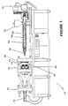
- FIG. 1 A typical molding apparatus useful in the practice of the present invention is described in detail below. Making reference now to the drawings where like numerals indicate like or corresponding parts throughout the figures, a molding apparatus is shown in FIG. 1, and is generally designed 10.
- Molding apparatus 10 includes a first mold half 20 which remains in a stationary or fixed position relative to a second moveable mold half 30.
- Figure 1 shows the mold halves in an open position.
- the first mold half and second mold half are adapted to slidingly mate, or nest to a mold cavity 40.
- the mold halves mate along surfaces 24 and 34 when the molding halves are in the closed position, forming parting line 42.
- the moveable mold half 30 reciprocates generally along a horizontal axis relative to the first or fixed mold half 20 by action of a clamping mechanism 70 with a clamp actuator 72 such as through a hydraulic or mechanical actuator as known in the art.
- the clamping pressure exerted by the clamping mechanism 70 has an operating pressure in excess of the pressures generated during molding.
- the mold halves 20 and 30 are shown in a closed position and contain workpiece 35 abut or mate along parting line 42.
- the mold cavity shows a cross section.
- the design of the mold cavity can vary greatly in size and shape according to the end product to be molded.
- the mold cavity has a first surface 44 on the first mold half, upon which a show surface of an article will be formed, and a corresponding or opposite second or non show surface 46 on the second mold half.
- the mold cavity may also contain separate orifices allowing injection through more than one injector.
- the first composition injector 50 is a typical injection molding apparatus which is well known to those of ordinary skill in the art and which is capable of injecting a thermoplastic or thermosetting composition into the mold cavity.
- the first composition injector is shown in a "backed off' position, but it is readily understood that the same can be moved to a horizontal direction so that nozzle or resin outlet 58 mates with mold half 20 and can inject into mold cavity 40.
- the first composition injector in FIG. 1 is a reciprocating-screw machine wherein a first composition may be placed in hopper 52 and rotating screw 56 moves the composition through the heated extruder barrel 54, where the material is heated above its melting point.
- the screw acts as an injection ram and forces the extrudate through the nozzle 58 into the mold.
- the nozzle generally has a non-return valve at the nozzle or screw tip to prevent backflow into the screw.
- the nozzle may also contain means to heat or cool to better control the temperature and thus flow properties of the extrudate.
- the extrudate may be injected into the mold from more than one location. In order to control the flow of the extrudate through this manifold, it may be necessary to heat the extrudate in order to make it flow easier or more rapidly.
- manifold passages may be referred to as hot runners or manifold systems and are shown in detail in FIG 3.
- the first composition injector is not meant to be limited to the embodiment shown in FIG. 1 but can be any apparatus capable of injecting a thermoplastic or thermosetting composition into the mold cavity. Suitable injection molding machines are available from Cincinnati Milacron, Battenfeld, Toshiba, Engel, Husky and others.
- a predetermined quantity of a first composition 80 is injected into the mold cavity from the first composition injector 50, forming a substrate or workpiece.
- the substrate formed in the mold cavity from the first composition has at least a show surface 82 and an opposite surface 84.
- a second composition 90 which is an in-mold coating composition, is then introduced into the mold cavity from the second injector 60.
- This injection is in the practice of this invention, begun after the previously injected material has begun to cool. This time is predetermined as described in more detail below.
- the second injector 60 is located in the mold half not containing the first composition injector 50. More specifically, the first composition injection 50 is located in the fixed mold half 20 and the second composition injector is located in the movable mold half 30.
- the in-mold coating composition 90 is injected through nozzle 62 into the mold cavity 40. It is important to note that the mold is not opened or unclamped before the in-mold coating is applied. That is, the mold halves maintain a parting line and remain in a closed position during the injection of both compositions.
- the in-mold coating composition spreads out and coats a predetermined portion or area of the substrate shown surface 82.
- FIG. 3 depicts a hypothetical first or stationary mold half of the general design shown in FIG. 1.
- the drawing depicts a typical runner system inside the mold which is used for the delivery of the plastic into the mold cavity and is illustrative of two types of gates namely those denominated hot tip and valve gate either of which may be used in the practice of this invention.
- 100 is a mold half.
- the polymer being fabricated is delivered from the injection unit through the bushing 112.
- a hot tip system is indicated by 160 and a valve gate system by 170.
- Cavity plate 110 is the portion of the mold adjacent the part to be formed.
- a nozzle tip insulator, the function of which is to prevent the cavity plate from acting as a heat sink, is indicated by 114.
- Nozzle heater 115 is also part of the system to maintain the correct temperature of the plastic being injected.
- the manifold heater 118 functions to keep the manifold hot.
- Sprue insulator 120 functions as part of the temperature maintenance system.
- Nozzle tip 122 is the actual point of delivery of the plastic into the mold and is located in nozzle housing 124. Cooling lines through which water or oil are circulated to heat or cool, as is required by the polymer being used, are indicated by 126 and 128.
- Manifold heater 130, nozzle insulator 132 and air gap 134 all are part of the temperature maintenance system.
- Locating ring 136 is used to locate the mold relative to the injection nozzle.
- Sprue heater 138 is located on sprue bushing 142.
- the manifold 140 generally is the basis or foundation for the whole system. Valve gate 144 is part of the delivery system for nozzle tip 122.
- Pressure transducer 180 measures eh pressure in the mold more than one such transducer is generally used.
- a temperature transducer 182 is used to determine the temperature in the mold. More than one such transducer is generally used.
- the injection of the plastic used to form the substrate into the mold in the practice of this invention may be viewed as a three-stage process.
- the first stage is usually referred to as injection high.
- the optimum pressure used to inject the plastic from the injection machine into the mold is determined by experimentation but it must be sufficiently great so that the mold is filled to at least about 75 percent of its capacity.
- the pressure time, plastic mold size and configuration are all determining factors. Generally the pressure is increased until flash is noticed at the parting line of the mold; then it is slightly decreased.
- injection pack The next stage of injection is referred to as injection pack. It too must be determined by a series of experiments and must be of a magnitude such that, at its completion, the mold cavity is filled to at least 99 percent of its capacity.
- injection hold is determined by experimentation.
- the function is to keep the workpiece from distorting.
- Pressures, times and other settings of the injection machine vary with the configuration of the mold, i.e. shape of the part being manufactured and the polymeric material being used.
- the volume of any given mold may be calculated. Based on this calculation and the density of the polymer, the size of the charge can be determined. Differing machine variables are tried until an optimum, complete filling of the mold in a minimum time, is determined.
- the mold is fitted with transducers which measure pressure and/or temperature, as various machine variables, e.g. injection speeds and pressures are altered.
- the determination of the optimum operating variables in the injection molding of a new part is basically a trial and error technique. While an experienced technician may have some idea as to what is required, he/she must nonetheless be prepared to generate a certain amount of scrap with any new set up. A choice is made of these variables, for example, barrel temperature, mold temperature, injection high pressure limit, injection hold pressure, injection speed, fill time, and holding time. Extreme adjustments are made in an effort to bracket operable conditions which may be fine tuned.
- the melt temperature of the molded substrate is reached. This is accomplished by using transducers to note when the temperature of the substrate reaches the melt temperature of the substrate.
- the melt temperature can be indirectly determined by observation of pressure, i.e. that is when the molded part reaches its melt temperature it starts to contract somewhat, thus reducing the pressure.
- the melt temperature is different with each different polymeric material.
- the time when the melt temperature is reached and injection of IMC commences is controlled by time. That is the length of time it takes from the time the mold closes until the substrate reaches its melt temperature is determined and is used to control the start of injection of IMC.
- Vandar 9114 As a substrate resin.
- the substrate resin had cooled below its 30 seconds after the mold closed.
Landscapes
- Engineering & Computer Science (AREA)
- Chemical & Material Sciences (AREA)
- Manufacturing & Machinery (AREA)
- Mechanical Engineering (AREA)
- Life Sciences & Earth Sciences (AREA)
- Materials Engineering (AREA)
- Wood Science & Technology (AREA)
- Organic Chemistry (AREA)
- Injection Moulding Of Plastics Or The Like (AREA)
- Moulds For Moulding Plastics Or The Like (AREA)
- Application Of Or Painting With Fluid Materials (AREA)
- Non-Metallic Protective Coatings For Printed Circuits (AREA)
Claims (8)
- Ein Verfahren zur Bildung eines In-Mold-beschichteten thermoplastischen Werkstücks, umfassend die Schritte:(a) Einspritzen eines thermoplastischen Materials, dessen Temperatur über seiner Schmelztemperatur liegt, mittels eines Einspritzdrucks in eine Form, die eine feste Formhälfte und eine bewegliche Formhälfte besitzt und die unter einem konstanten Klemmdruck, der größer ist als der Einspritzdruck, in einer geschlossenen Position gehalten wird, um wenigstens 75 Prozent der Form auszufüllen,(b) Fortsetzen des Einspritzens des thermoplastischen Materials, dessen Temperatur bei oder über seiner Schmelztemperatur liegt, in die Form, die unter dem Klemmdruck in einer geschlossenen Position gehalten wird, mittels eines Einspritz-Packdrucks in einer Einspritz-Packphase, bis die Form zu wenigstens 99 Prozent ihres Fassungsvermögens gefüllt ist, wobei der Packdruck während der gesamten Packphase konstant gehalten wird,(c) Halten des thermoplastischen Materials, während es abkühlt, unter einem Haltedruck, der geringer ist als der Einspritz-Packdruck, in einer Haltephase in der geschlossenen Form, die unter dem konstanten Klemmdruck gehalten wird, um ein Werkstück zu bilden, wobei der Haltedruck während der gesamten Haltephase konstant gehalten wird,(d) Einspritzen einer vorbestimmten Menge an In-Mold-Beschichtungsmaterial in die geschlossene Form, während diese unter dem konstanten Klemmdruck gehalten wird und unmittelbar nachdem die Oberflächentemperatur des Thermoplasten, der das Werkstück bildet, unter dessen Schmelztemperatur fällt, um wenigstens einen Teil der Oberflächen des Werkstücks zu beschichten, und(e) Lösen des Klemmdrucks, Öffnen der Form und Entnehmen des In-Mold-beschichteten Werkstücks, nachdem das In-Mold-beschichtete Material wenigstens teilweise gehärtet ist.
- Das Verfahren nach Anspruch 1, wobei der Thermoplast ausgewählt ist aus der Gruppe, bestehend aus Polyester, Polystyrol, PBT-Copolymer, Polypropylen, TPUs, ABS, PVC, Polycarbonaten, PP/PS-Legierungen, Polyethylen, Nylon, Polyacetal, SAN, Acrylharzen, PC-Legierungen und PP-Legierungen.
- Das Verfahren nach den Ansprüchen 1 bis 2, wobei das In-Mold-Beschichtungsmaterial eine duroplastische Zusammensetzung ist, die durch radikalische Initiierung bei einer Temperatur unterhalb der Schmelztemperatur des Thermoplasten gehärtet werden kann.
- Ein Verfahren gemäß irgendeinem der Ansprüche 1-3, wobei das In-Mold-Beschichtungsmaterial hergeleitet ist aus wenigstens einem Acryloligomer aus einem gesättigten aliphatischen Polyesterurethan-Zwischenprodukt, einem gesättigten (cyclo)-aliphatischen (Meth)acrylat, einem oder mehreren Hydroxyalkyl(meth)acrylaten, einem Polyacrylatester eines Alkylenpolyols, einem oder mehreren vinylsubstituierten Aromaten und einem Starter, der in der Lage ist, Radikale in der Beschichtungszusammensetzung zu erzeugen.
- Ein Verfahren gemäß irgendeinem der Ansprüche 1-4, wobei das In-Mold-Beschichtungsmaterial einen Starter enthält, ausgewählt aus der Gruppe, bestehend aus tert.-Butylperbenzoat, tert.-Butylperoctoat und Mischungen davon.
- Ein Verfahren gemäß irgendeinem der Ansprüche 1-4, wobei das In-Mold-Beschichtungsmaterial eine Peroxidverbindung als Starter enthält.
- Ein Verfahren gemäß Anspruch 6, wobei die Peroxidverbindung ausgewählt ist aus der Gruppe, bestehend aus Diacetylperoxid in Dimethylphthalat, Dibenzoylperoxid, Di(p-chlorbenzoyl)peroxid in Dibutylphthalat, Di(2,4-dichlorbenzoyl)peroxid in Dibutylphthalat, Dilauroylperoxid, Methylethylketonperoxid, Cyclohexanonperoxid in Dibutylphthalat, 3,5-Dihydroxy-3,4-dimethyl-1,2-dioxacyclopentan, t-Butylperoxy(2-ethyl-hexanoat), Caprylylperoxid, 2,5-Dimethyl-2,5-di(benzoylperoxy)hexan, 1-Hydroxycyclohexylhydroperoxid-1, t-Butylperoxy(2-ethylbutyrat), 2,5-Dimethyl-2,5-bis(t-butylperoxy)-hexan, Cumolhydroperoxid, Diacetylperoxid, t-Butylhydroperoxid, Di-tert.-butylperoxid, 3,5-Dihydroxy-3,5-dimethyl-1,2-oxacyclopentan, 1,1-Bis(t-butylperoxy)-3,3,5-trimethylcyclohexan und Mischungen davon.
- Ein Verfahren gemäß Anspruch 4, wobei der Starter in einer Menge von etwa 0,25 Gew.-% bis etwa 5 Gew.-%, bezogen auf das Gesamtgewicht der Komponenten, die das In-Mold-Beschichtungsmaterial ausmachen, enthalten ist.
Applications Claiming Priority (3)
| Application Number | Priority Date | Filing Date | Title |
|---|---|---|---|
| US974644 | 1978-12-29 | ||
| US09/974,644 US6793861B2 (en) | 2000-07-12 | 2001-10-09 | Optimization of in-mold coating injection molded thermoplastic substrates |
| PCT/US2002/004023 WO2003031138A1 (en) | 2001-10-09 | 2002-02-11 | Optimization of in-mold coating injection molded thermoplastic substrates |
Publications (2)
| Publication Number | Publication Date |
|---|---|
| EP1434676A1 EP1434676A1 (de) | 2004-07-07 |
| EP1434676B1 true EP1434676B1 (de) | 2007-05-30 |
Family
ID=25522302
Family Applications (1)
| Application Number | Title | Priority Date | Filing Date |
|---|---|---|---|
| EP02706235A Expired - Lifetime EP1434676B1 (de) | 2001-10-09 | 2002-02-11 | Verbesserung eines imc-beschichtungsverfahrens von spritzgegossenen thermoplastischen substraten |
Country Status (10)
| Country | Link |
|---|---|
| US (1) | US6793861B2 (de) |
| EP (1) | EP1434676B1 (de) |
| JP (1) | JP4914559B2 (de) |
| KR (1) | KR20040072618A (de) |
| AT (1) | ATE363369T1 (de) |
| BR (1) | BR0213230A (de) |
| CA (1) | CA2503311C (de) |
| DE (1) | DE60220428T2 (de) |
| MX (1) | MXPA04003337A (de) |
| WO (1) | WO2003031138A1 (de) |
Families Citing this family (37)
| Publication number | Priority date | Publication date | Assignee | Title |
|---|---|---|---|---|
| MXPA02010360A (es) * | 2000-04-20 | 2004-09-10 | Omnova Solutions Inc | Metodo para moldear un panel. |
| US20040071980A1 (en) * | 2000-07-12 | 2004-04-15 | Mcbain Douglas S. | Method for in-mold coating a polyolefin article |
| US7045213B2 (en) * | 2001-10-22 | 2006-05-16 | Omnova Solutions Inc. | In-mold coating injection inlet flow control |
| US6887550B2 (en) * | 2001-10-22 | 2005-05-03 | Omnova Solutions Inc. | Removable defined flange for in-mold coating containment |
| US7105231B2 (en) * | 2001-10-22 | 2006-09-12 | Omnova Solutions Inc. | In-mold coating barrier for a substrate injection orifice |
| US6676877B2 (en) * | 2002-04-03 | 2004-01-13 | Omnova Solutions Inc. | Mold runner for prevention of in-mold coating flow |
| WO2004014990A1 (en) * | 2002-08-10 | 2004-02-19 | Omnova Solutions Inc. | Method for coating molded thermoplastic articles |
| CN100413669C (zh) * | 2002-08-23 | 2008-08-27 | 普瑞曼聚合物株式会社 | 模具内被覆成型体及其制造方法 |
| WO2004041502A1 (en) * | 2002-10-31 | 2004-05-21 | Omnova Solutions Inc. | Method and apparatus for metering and controlling dispense rate |
| JP2006504558A (ja) * | 2002-10-31 | 2006-02-09 | オムノバ ソリューソンズ インコーポレーティッド | 射出成形された物品をコーティングする方法並びに供給および制御装置 |
| WO2004043671A1 (en) * | 2002-11-08 | 2004-05-27 | Omnova Solutions Inc. | Quality assurance method for coated parts |
| EP1560691A2 (de) * | 2002-11-08 | 2005-08-10 | Omnova Solutions Inc. | Druck- und temperaturführung bei beschichtung im werkzeug |
| CN100395095C (zh) * | 2002-11-22 | 2008-06-18 | 阿姆诺洼化学有限公司 | 利用模内涂层装置对现有模具系统进行改进的方法 |
| AU2003290839A1 (en) * | 2002-11-22 | 2004-06-18 | Omnova Solutions Inc. | Method for retrofitting existing molds for use with an in-mold coating system |
| KR100969694B1 (ko) * | 2002-11-25 | 2010-07-14 | 우베 고산 기카이 가부시키가이샤 | 몰드내 피복성형방법 및 몰드내 피복성형품 |
| US20040121034A1 (en) * | 2002-12-10 | 2004-06-24 | Mcbain Douglas S. | Integral injection molding and in-mold coating apparatus |
| CN100441392C (zh) * | 2002-12-12 | 2008-12-10 | 阿姆诺洼化学有限公司 | 设计和制造模具的方法 |
| US20040148051A1 (en) * | 2003-01-28 | 2004-07-29 | Omnova Solutions, Inc. | Modeling method and program for in-mold coating an injection molded thermoplastic article |
| WO2004094127A1 (en) * | 2003-03-27 | 2004-11-04 | Omnova Solutions Inc. | Coating in multiple injection molding part cavities |
| CN1618595B (zh) * | 2003-11-20 | 2011-08-24 | 鸿富锦精密工业(深圳)有限公司 | 注射成型装置 |
| US20050156351A1 (en) * | 2004-01-20 | 2005-07-21 | Omnova Solutions, Inc. | Apparatus and method for in-mold coating an article by injecting an in-mold coating through the article |
| KR100645467B1 (ko) | 2004-03-22 | 2006-11-13 | 주식회사 우성기업 | 자동차용 스포일러의 제조방법 |
| US20060082010A1 (en) * | 2004-10-19 | 2006-04-20 | Saggese Stefano M | Intelligent molding environment and method of controlling applied clamp tonnage |
| JP4456991B2 (ja) * | 2004-11-30 | 2010-04-28 | 豊田合成株式会社 | 成形品の成形方法 |
| US7833442B2 (en) * | 2005-12-21 | 2010-11-16 | Essilor International (Compagnie Generale D'optique) | Method for coating an ophthalmic lens within an injection molding machine |
| US7906047B2 (en) | 2005-12-21 | 2011-03-15 | Essilor International (Compagnie Generale D'optique) | Injection molding a lens onto a coated ophthalmic wafer |
| US8202335B2 (en) * | 2006-10-10 | 2012-06-19 | Us Synthetic Corporation | Superabrasive elements, methods of manufacturing, and drill bits including same |
| KR100906348B1 (ko) * | 2007-04-18 | 2009-07-06 | 이범주 | 앨범표지 제작용 고정틀과, 앨범표지의 제작장치 및 이를사용한 앨범표지의 제작방법 |
| JP5501957B2 (ja) * | 2007-04-27 | 2014-05-28 | エグザテック・リミテッド・ライアビリティー・カンパニー | モールド内被覆による耐摩耗性プラスチックの艶出し |
| WO2008134771A1 (en) | 2007-05-01 | 2008-11-06 | Exatec, Llc | Encapsulated plastic panel and method of making the same |
| WO2008141136A1 (en) * | 2007-05-09 | 2008-11-20 | Exatec. Llc | Pre-dry treatment of ink in decorative plastic glazing |
| US8088318B2 (en) * | 2007-06-05 | 2012-01-03 | Magna International Inc. | Method for processing an interior trim component |
| US7759433B2 (en) | 2007-06-20 | 2010-07-20 | Essilor International (Compagnie Generale D'optique) | High adhesion acrylate coating for a photochromic ophthalmic lens |
| US7820082B2 (en) * | 2007-06-20 | 2010-10-26 | Essilor International (Compagne Generale D'optique) | Method for adding a thermoset overmold layer to a lens within a mold |
| CN109501188B (zh) * | 2018-12-25 | 2021-05-18 | 河源市昌红精机科技有限公司 | 一种打印机底壳及其注塑射胶控制方法 |
| CN109501189B (zh) * | 2018-12-25 | 2021-05-18 | 河源市昌红精机科技有限公司 | 一种打印机底壳及其注塑控制方法 |
| CN116080095B (zh) * | 2023-01-30 | 2023-09-19 | 浙江久石工研建材科技有限公司 | 一种仿夯土柔性贴片石制作工艺 |
Family Cites Families (42)
| Publication number | Priority date | Publication date | Assignee | Title |
|---|---|---|---|---|
| US2337550A (en) | 1939-08-21 | 1943-12-28 | Hydraulic Dev Corp Inc | Die casting-plastic injection method of molding |
| US4081578A (en) | 1974-06-27 | 1978-03-28 | The General Tire & Rubber Company | In-mold coating composition and method of applying same |
| US4076788A (en) | 1976-12-02 | 1978-02-28 | General Motors Corporation | Mold coating of freshly molded articles |
| US4118051A (en) | 1976-12-17 | 1978-10-03 | Nissei Plastics Industrial Co., Ltd. | Injection molded ski and method for producing the same |
| US4189517A (en) | 1978-11-08 | 1980-02-19 | The General Tire & Rubber Company | Low-shrink in-mold coating |
| US4222929A (en) | 1978-11-08 | 1980-09-16 | The General Tire & Rubber Company | Low-shrink in-mold coating |
| NL7903428A (nl) | 1979-05-02 | 1980-11-04 | Stamicarbon | Werkwijze voor het vervaardigen van uit thermohardende hars gevormde voorwerpen. |
| US4350739A (en) | 1979-07-30 | 1982-09-21 | International Telephone And Telegraph Corporation | Molded plastic part |
| US4366109A (en) | 1980-05-01 | 1982-12-28 | Freeman Chemical Corporation | Method for making coated molded articles |
| US4331735A (en) | 1980-06-26 | 1982-05-25 | The General Tire & Rubber Company | One component in-mold coating |
| US4389358A (en) | 1981-06-22 | 1983-06-21 | Kmmco Structural Foam, Inc. | Method and apparatus for making an integral structural cellular and non-cellular plastic or resinous article with a smooth outer surface |
| US4414173A (en) | 1981-11-02 | 1983-11-08 | The General Tire & Rubber Company | In-mold coating |
| US4515710A (en) | 1983-07-18 | 1985-05-07 | Gencorp Inc. | In-mold coating composition |
| US4668460A (en) | 1985-04-02 | 1987-05-26 | The Sherwin-Williams Company | Method of molding and coating a substrate in a mold. |
| JPS62160216A (ja) | 1986-01-08 | 1987-07-16 | Mazda Motor Corp | インモ−ルドコ−ト方法及びその装置 |
| JPS62227712A (ja) | 1986-03-31 | 1987-10-06 | Toyo Seikan Kaisha Ltd | オレフィン―ビニルアルコール共重合体の射出成形体及びその製法 |
| US4808361A (en) * | 1987-03-16 | 1989-02-28 | Gencorp Inc. | Method for forming an in-mold coated fiber reinforced part |
| DE3736280A1 (de) | 1987-10-27 | 1989-05-11 | Roehm Gmbh | Verfahren zur herstellung kratzfest beschichteter extrudierter kunststoffbahnen |
| US5071603A (en) * | 1987-12-14 | 1991-12-10 | Kabushiki Kaisha Kobe Seiko Sho | Method of controlling hydraulic press |
| DE3811112A1 (de) | 1988-03-31 | 1989-10-12 | Fritz Mueller | Spritzgussverfahren fuer kunststoffe und spritzgussform |
| DE3816855A1 (de) | 1988-05-18 | 1989-11-23 | Roehm Gmbh | Verfahren zur herstellung kratzfest beschichteter kunststoffbahnen |
| US5084353A (en) | 1989-05-12 | 1992-01-28 | Gencorp Inc. | Thermosetting in-mold coating compositions |
| JPH03178412A (ja) * | 1989-12-07 | 1991-08-02 | Mazda Motor Corp | インモールドコート方法 |
| US5132052A (en) | 1991-03-20 | 1992-07-21 | Gencorp Inc. | Fast cure in-mold coating |
| JP2686682B2 (ja) | 1991-10-16 | 1997-12-08 | いすゞ自動車株式会社 | 成形品の製造方法 |
| CA2130120A1 (en) | 1992-02-21 | 1993-09-02 | John Michael Fisher | Recyclable molded high modulus fiber reinforced thermoplastic structures and process for preparing the same |
| GB9204730D0 (en) | 1992-03-05 | 1992-04-15 | Rover Group | A method of forming a moulding by dual injection and a moulding formed in accordance with such a method |
| US5906788A (en) | 1992-10-05 | 1999-05-25 | Cook Composites And Polymers Co. | Dual cure, in-mold process for manufacturing abrasion resistant, coated thermoplastic articles |
| EP0622386B1 (de) | 1993-04-26 | 1998-01-28 | Gencorp Inc. | Leitfähige Formbeschichtungen |
| JPH08227637A (ja) | 1994-02-23 | 1996-09-03 | Matsushita Electric Works Ltd | コントロールスイッチ及びその製造方法 |
| DE4414258C2 (de) | 1994-04-23 | 1996-07-25 | Battenfeld Gmbh | Verfahren zum Spritzgießen von mindestens aus zwei unterschiedlichen Schichten bestehenden Gegenständen |
| US5902534A (en) | 1994-09-21 | 1999-05-11 | Mitsubishi Engineering-Plastics Corp. | Method of injection-molding thermoplastic resins |
| JP3404546B2 (ja) | 1995-03-23 | 2003-05-12 | 大日本塗料株式会社 | 金型内被覆方法 |
| US5658672A (en) | 1995-05-08 | 1997-08-19 | Gencorp Inc. | In-mold coating composition |
| JP3599441B2 (ja) | 1995-08-11 | 2004-12-08 | 三菱エンジニアリングプラスチックス株式会社 | 型内被覆成形法用の金型 |
| US5849168A (en) | 1996-06-14 | 1998-12-15 | Acushnet Company | Method of in-mold coating golf balls |
| US6328920B1 (en) | 1996-11-27 | 2001-12-11 | Honda Engineering North America, Inc. | Molding process for forming complex shapes |
| US5777053A (en) | 1997-01-17 | 1998-07-07 | Gencorp Inc. | In-mold coating compositions suitable as is for an end use application |
| US6180043B1 (en) | 1998-01-27 | 2001-01-30 | Dai Nippon Toryo Co., Ltd. | Method of in-mold coating |
| FR2778134B1 (fr) | 1998-04-29 | 2000-08-11 | Oreal | Procede et dispositif pour la fabrication de pieces peintes ou vernies en matiere plastique moulee |
| WO2001007230A1 (fr) | 1999-07-27 | 2001-02-01 | Dai Nippon Toryo Co., Ltd. | Procede de formation d'un revetement sur les surfaces internes d'un moule metallique |
| MXPA02010360A (es) | 2000-04-20 | 2004-09-10 | Omnova Solutions Inc | Metodo para moldear un panel. |
-
2001
- 2001-10-09 US US09/974,644 patent/US6793861B2/en not_active Expired - Lifetime
-
2002
- 2002-02-11 JP JP2003534152A patent/JP4914559B2/ja not_active Expired - Fee Related
- 2002-02-11 BR BR0213230A patent/BR0213230A/pt not_active IP Right Cessation
- 2002-02-11 MX MXPA04003337A patent/MXPA04003337A/es not_active Application Discontinuation
- 2002-02-11 AT AT02706235T patent/ATE363369T1/de not_active IP Right Cessation
- 2002-02-11 EP EP02706235A patent/EP1434676B1/de not_active Expired - Lifetime
- 2002-02-11 KR KR10-2004-7005304A patent/KR20040072618A/ko not_active Application Discontinuation
- 2002-02-11 WO PCT/US2002/004023 patent/WO2003031138A1/en active IP Right Grant
- 2002-02-11 DE DE2002620428 patent/DE60220428T2/de not_active Expired - Lifetime
- 2002-02-11 CA CA 2503311 patent/CA2503311C/en not_active Expired - Lifetime
Also Published As
| Publication number | Publication date |
|---|---|
| JP2005504658A (ja) | 2005-02-17 |
| DE60220428D1 (de) | 2007-07-12 |
| CA2503311C (en) | 2008-05-20 |
| CA2503311A1 (en) | 2003-04-17 |
| JP4914559B2 (ja) | 2012-04-11 |
| WO2003031138A8 (en) | 2005-03-24 |
| US20020039656A1 (en) | 2002-04-04 |
| BR0213230A (pt) | 2004-09-28 |
| ATE363369T1 (de) | 2007-06-15 |
| WO2003031138A1 (en) | 2003-04-17 |
| DE60220428T2 (de) | 2008-01-31 |
| US6793861B2 (en) | 2004-09-21 |
| MXPA04003337A (es) | 2006-02-22 |
| EP1434676A1 (de) | 2004-07-07 |
| KR20040072618A (ko) | 2004-08-18 |
Similar Documents
| Publication | Publication Date | Title |
|---|---|---|
| EP1434676B1 (de) | Verbesserung eines imc-beschichtungsverfahrens von spritzgegossenen thermoplastischen substraten | |
| EP1441888B1 (de) | Verfahren zum aufbringen einer imc-(in-mold-coating)-beschichtung auf einem oberflächenbereich eines spritzgegossenen substrates | |
| US5902534A (en) | Method of injection-molding thermoplastic resins | |
| US6676877B2 (en) | Mold runner for prevention of in-mold coating flow | |
| EP1299218B1 (de) | Verfahren zum in-der-form-beschichten eines polyolefin-gegenstandes | |
| WO2001007230A1 (fr) | Procede de formation d'un revetement sur les surfaces internes d'un moule metallique | |
| US7105231B2 (en) | In-mold coating barrier for a substrate injection orifice | |
| US7045213B2 (en) | In-mold coating injection inlet flow control | |
| US6887550B2 (en) | Removable defined flange for in-mold coating containment | |
| US20050156351A1 (en) | Apparatus and method for in-mold coating an article by injecting an in-mold coating through the article | |
| US20040071980A1 (en) | Method for in-mold coating a polyolefin article | |
| US7790081B2 (en) | Method of manufacturing formed product coated in mold | |
| EP1501668B1 (de) | Selektive kontrolle eines in der form beschichtungsflusses mit eintrittsdurchflusssteuerung und mit einem abnehmbaren abdichtungsflansch | |
| KR20050019098A (ko) | 열가소성 기재를 위한 인몰드 프리미어 코팅 | |
| JP2001038783A (ja) | 金型内被覆成形方法及び金型内被覆成形装置 | |
| WO2004085549A2 (en) | Optical quality coating | |
| WO2004014990A1 (en) | Method for coating molded thermoplastic articles |
Legal Events
| Date | Code | Title | Description |
|---|---|---|---|
| PUAI | Public reference made under article 153(3) epc to a published international application that has entered the european phase |
Free format text: ORIGINAL CODE: 0009012 |
|
| 17P | Request for examination filed |
Effective date: 20040416 |
|
| AK | Designated contracting states |
Kind code of ref document: A1 Designated state(s): AT BE CH CY DE DK ES FI FR GB GR IE IT LI LU MC NL PT SE TR |
|
| 17Q | First examination report despatched |
Effective date: 20041105 |
|
| GRAP | Despatch of communication of intention to grant a patent |
Free format text: ORIGINAL CODE: EPIDOSNIGR1 |
|
| GRAS | Grant fee paid |
Free format text: ORIGINAL CODE: EPIDOSNIGR3 |
|
| GRAA | (expected) grant |
Free format text: ORIGINAL CODE: 0009210 |
|
| AK | Designated contracting states |
Kind code of ref document: B1 Designated state(s): AT BE CH CY DE DK ES FI FR GB GR IE IT LI LU MC NL PT SE TR |
|
| PG25 | Lapsed in a contracting state [announced via postgrant information from national office to epo] |
Ref country code: CH Free format text: LAPSE BECAUSE OF FAILURE TO SUBMIT A TRANSLATION OF THE DESCRIPTION OR TO PAY THE FEE WITHIN THE PRESCRIBED TIME-LIMIT Effective date: 20070530 Ref country code: FI Free format text: LAPSE BECAUSE OF FAILURE TO SUBMIT A TRANSLATION OF THE DESCRIPTION OR TO PAY THE FEE WITHIN THE PRESCRIBED TIME-LIMIT Effective date: 20070530 Ref country code: LI Free format text: LAPSE BECAUSE OF FAILURE TO SUBMIT A TRANSLATION OF THE DESCRIPTION OR TO PAY THE FEE WITHIN THE PRESCRIBED TIME-LIMIT Effective date: 20070530 |
|
| REG | Reference to a national code |
Ref country code: GB Ref legal event code: FG4D |
|
| REG | Reference to a national code |
Ref country code: CH Ref legal event code: EP |
|
| REG | Reference to a national code |
Ref country code: IE Ref legal event code: FG4D |
|
| REF | Corresponds to: |
Ref document number: 60220428 Country of ref document: DE Date of ref document: 20070712 Kind code of ref document: P |
|
| PG25 | Lapsed in a contracting state [announced via postgrant information from national office to epo] |
Ref country code: SE Free format text: LAPSE BECAUSE OF FAILURE TO SUBMIT A TRANSLATION OF THE DESCRIPTION OR TO PAY THE FEE WITHIN THE PRESCRIBED TIME-LIMIT Effective date: 20070830 |
|
| PG25 | Lapsed in a contracting state [announced via postgrant information from national office to epo] |
Ref country code: ES Free format text: LAPSE BECAUSE OF FAILURE TO SUBMIT A TRANSLATION OF THE DESCRIPTION OR TO PAY THE FEE WITHIN THE PRESCRIBED TIME-LIMIT Effective date: 20070910 |
|
| ET | Fr: translation filed | ||
| PG25 | Lapsed in a contracting state [announced via postgrant information from national office to epo] |
Ref country code: AT Free format text: LAPSE BECAUSE OF FAILURE TO SUBMIT A TRANSLATION OF THE DESCRIPTION OR TO PAY THE FEE WITHIN THE PRESCRIBED TIME-LIMIT Effective date: 20070530 |
|
| REG | Reference to a national code |
Ref country code: CH Ref legal event code: PL |
|
| PG25 | Lapsed in a contracting state [announced via postgrant information from national office to epo] |
Ref country code: BE Free format text: LAPSE BECAUSE OF FAILURE TO SUBMIT A TRANSLATION OF THE DESCRIPTION OR TO PAY THE FEE WITHIN THE PRESCRIBED TIME-LIMIT Effective date: 20070530 |
|
| PG25 | Lapsed in a contracting state [announced via postgrant information from national office to epo] |
Ref country code: PT Free format text: LAPSE BECAUSE OF FAILURE TO SUBMIT A TRANSLATION OF THE DESCRIPTION OR TO PAY THE FEE WITHIN THE PRESCRIBED TIME-LIMIT Effective date: 20071030 Ref country code: DK Free format text: LAPSE BECAUSE OF FAILURE TO SUBMIT A TRANSLATION OF THE DESCRIPTION OR TO PAY THE FEE WITHIN THE PRESCRIBED TIME-LIMIT Effective date: 20070530 |
|
| PLBE | No opposition filed within time limit |
Free format text: ORIGINAL CODE: 0009261 |
|
| STAA | Information on the status of an ep patent application or granted ep patent |
Free format text: STATUS: NO OPPOSITION FILED WITHIN TIME LIMIT |
|
| PG25 | Lapsed in a contracting state [announced via postgrant information from national office to epo] |
Ref country code: IT Free format text: LAPSE BECAUSE OF FAILURE TO SUBMIT A TRANSLATION OF THE DESCRIPTION OR TO PAY THE FEE WITHIN THE PRESCRIBED TIME-LIMIT Effective date: 20070530 Ref country code: GR Free format text: LAPSE BECAUSE OF FAILURE TO SUBMIT A TRANSLATION OF THE DESCRIPTION OR TO PAY THE FEE WITHIN THE PRESCRIBED TIME-LIMIT Effective date: 20070831 |
|
| 26N | No opposition filed |
Effective date: 20080303 |
|
| PG25 | Lapsed in a contracting state [announced via postgrant information from national office to epo] |
Ref country code: MC Free format text: LAPSE BECAUSE OF NON-PAYMENT OF DUE FEES Effective date: 20080228 |
|
| PG25 | Lapsed in a contracting state [announced via postgrant information from national office to epo] |
Ref country code: IE Free format text: LAPSE BECAUSE OF NON-PAYMENT OF DUE FEES Effective date: 20080211 |
|
| PG25 | Lapsed in a contracting state [announced via postgrant information from national office to epo] |
Ref country code: CY Free format text: LAPSE BECAUSE OF FAILURE TO SUBMIT A TRANSLATION OF THE DESCRIPTION OR TO PAY THE FEE WITHIN THE PRESCRIBED TIME-LIMIT Effective date: 20070530 |
|
| PG25 | Lapsed in a contracting state [announced via postgrant information from national office to epo] |
Ref country code: LU Free format text: LAPSE BECAUSE OF NON-PAYMENT OF DUE FEES Effective date: 20080211 |
|
| PG25 | Lapsed in a contracting state [announced via postgrant information from national office to epo] |
Ref country code: TR Free format text: LAPSE BECAUSE OF FAILURE TO SUBMIT A TRANSLATION OF THE DESCRIPTION OR TO PAY THE FEE WITHIN THE PRESCRIBED TIME-LIMIT Effective date: 20070530 |
|
| REG | Reference to a national code |
Ref country code: FR Ref legal event code: PLFP Year of fee payment: 15 |
|
| REG | Reference to a national code |
Ref country code: FR Ref legal event code: PLFP Year of fee payment: 16 |
|
| REG | Reference to a national code |
Ref country code: FR Ref legal event code: PLFP Year of fee payment: 17 |
|
| PGFP | Annual fee paid to national office [announced via postgrant information from national office to epo] |
Ref country code: FR Payment date: 20210120 Year of fee payment: 20 Ref country code: NL Payment date: 20210115 Year of fee payment: 20 |
|
| PGFP | Annual fee paid to national office [announced via postgrant information from national office to epo] |
Ref country code: DE Payment date: 20210113 Year of fee payment: 20 Ref country code: GB Payment date: 20210129 Year of fee payment: 20 |
|
| REG | Reference to a national code |
Ref country code: DE Ref legal event code: R071 Ref document number: 60220428 Country of ref document: DE |
|
| REG | Reference to a national code |
Ref country code: NL Ref legal event code: MK Effective date: 20220210 |
|
| REG | Reference to a national code |
Ref country code: GB Ref legal event code: PE20 Expiry date: 20220210 |
|
| PG25 | Lapsed in a contracting state [announced via postgrant information from national office to epo] |
Ref country code: GB Free format text: LAPSE BECAUSE OF EXPIRATION OF PROTECTION Effective date: 20220210 |