EP1433574B1 - Fernsteuervorrichtung für beweglichen zweibeinigen roboter - Google Patents
Fernsteuervorrichtung für beweglichen zweibeinigen roboter Download PDFInfo
- Publication number
- EP1433574B1 EP1433574B1 EP02760670A EP02760670A EP1433574B1 EP 1433574 B1 EP1433574 B1 EP 1433574B1 EP 02760670 A EP02760670 A EP 02760670A EP 02760670 A EP02760670 A EP 02760670A EP 1433574 B1 EP1433574 B1 EP 1433574B1
- Authority
- EP
- European Patent Office
- Prior art keywords
- moving
- mobile robot
- moving amount
- robot
- leg
- Prior art date
- Legal status (The legal status is an assumption and is not a legal conclusion. Google has not performed a legal analysis and makes no representation as to the accuracy of the status listed.)
- Expired - Fee Related
Links
Images


Classifications
-
- B—PERFORMING OPERATIONS; TRANSPORTING
- B62—LAND VEHICLES FOR TRAVELLING OTHERWISE THAN ON RAILS
- B62D—MOTOR VEHICLES; TRAILERS
- B62D57/00—Vehicles characterised by having other propulsion or other ground- engaging means than wheels or endless track, alone or in addition to wheels or endless track
- B62D57/02—Vehicles characterised by having other propulsion or other ground- engaging means than wheels or endless track, alone or in addition to wheels or endless track with ground-engaging propulsion means, e.g. walking members
- B62D57/032—Vehicles characterised by having other propulsion or other ground- engaging means than wheels or endless track, alone or in addition to wheels or endless track with ground-engaging propulsion means, e.g. walking members with alternately or sequentially lifted supporting base and legs; with alternately or sequentially lifted feet or skid
-
- B—PERFORMING OPERATIONS; TRANSPORTING
- B25—HAND TOOLS; PORTABLE POWER-DRIVEN TOOLS; MANIPULATORS
- B25J—MANIPULATORS; CHAMBERS PROVIDED WITH MANIPULATION DEVICES
- B25J5/00—Manipulators mounted on wheels or on carriages
-
- B—PERFORMING OPERATIONS; TRANSPORTING
- B25—HAND TOOLS; PORTABLE POWER-DRIVEN TOOLS; MANIPULATORS
- B25J—MANIPULATORS; CHAMBERS PROVIDED WITH MANIPULATION DEVICES
- B25J13/00—Controls for manipulators
- B25J13/02—Hand grip control means
-
- B—PERFORMING OPERATIONS; TRANSPORTING
- B25—HAND TOOLS; PORTABLE POWER-DRIVEN TOOLS; MANIPULATORS
- B25J—MANIPULATORS; CHAMBERS PROVIDED WITH MANIPULATION DEVICES
- B25J13/00—Controls for manipulators
- B25J13/06—Control stands, e.g. consoles, switchboards
Definitions
- the present invention relates to a robot system comprising a bipedal mobile robot and a remote control device for moving the bipedal mobile robot.
- a bipedal mobile robot which has been planed to be in a practical use by the present applicants and the like, moves by an action for making two legs to alternately lift and land like a human.
- movement of the bipedal mobile robot includes a movement from one place to another place, as well as such an action as turning almost in the same place to change orientation of the robot.
- a moving direction of the robot means a turning direction such as a clockwise direction and a counterclockwise direction.
- a stopped state of the bipedal mobile robot is a state that the movement of the robot is not performed, so that a state with the two legs stopped as well as such a state as the robot is marching in the same place without changing orientation are included.
- the present applicants attempt to establish a system for manipulating to move such a bipedal mobile robot by a remote controller having a manipulator lever such as a joystick.
- a moving direction and a stride of the robot is determined in real time depending on a manipulating direction and a manipulation amount of a manipulator lever of a remote controller, thereby activating the legs of the robot according to these determined moving direction and stride.
- the manipulator lever when an attempt is made to move the robot to a desired position, the manipulator lever has to be operated by a manipulation amount corresponding to a moving amount from a current position to the desired position, but this manipulating amount is difficult to delicately be adjusted. Accordingly, for example, it is difficult to operate such a manipulator lever as that the robot is moved by a relatively minute amount (such a moving amount as a movement can be made by one step) from one place to another place and stopped. Additionally, even when a place to be reached last is known, the manipulation amount of the manipulator lever is difficult to accurately be adjusted while moving the robot toward the place, and as a result, it is difficult to make the robot to surely reach the desired place.
- the present invention relates to a robot system comprising a bipedal mobile robot and a remote control device for moving the bipedal mobile robot by an action for alternately lifting and landing two legs, and in order to achieve the above-mentioned object, there are three basic aspects to the invention.
- the robot system comprises a manipulator lever for commanding a moving direction of the bipedal mobile robot, and is characterized by comprising moving amount setting means for counting a number of times that the manipulator lever is operated from a non-manipulation state to a manipulation state corresponding to a desired direction of the bipedal mobile robot until predetermined manipulation completing conditions are satisfied in a stopped state of the bipedal mobile robot and setting the moving amount of the bipedal mobile robot in the desired direction in correspondence with the counted number, and movement control means for making the bipedal mobile robot move toward the desired moving direction according to the set moving amount.
- moving amount setting means counts the number of operations of the manipulator lever to the manipulation state corresponding to the desired direction of the bipedal mobile robot until the predetermined manipulation completing conditions for judging the above completion of the manipulator lever are satisfied, and thereby setting the moving amount of the bipedal mobile robot toward the desired direction depending on the counted number.
- the movement of the bipedal mobile robot toward the desired direction according to the set moving amount is then carried out by a control by the movement control means.
- the moving amount of the bipedal mobile robot toward the desired direction can be set according to the number of operations of the manipulator lever in the stopped state of the bipedal mobile robot, so that this setting may easily be performed. Consequently, the operation for moving the robot in the desired direction to the desired position may easily and surely be performed, so that the movement of the robot to the desired position may surely be performed by a simple operation.
- the manipulation completing conditions include, for example, whether or not a confirmation switch provided beforehand in the remote control device is operated, or whether or not the manipulator lever is maintained in the non-manipulation state for more than a predetermined fixed period of time, etc.
- the moving amount setting means counts the number of times the manipulator lever is operated into a manipulation state corresponding to a moving direction for each type of moving directions, and sets the moving amount of the bipedal mobile robot depending on the counted number of times for each type of the moving directions, and the movement control means combines the set moving amounts for each type of the moving directions to make the bipedal mobile robot move.
- the operator sets a required moving amount of the robot according to the number of operations of the manipulator lever for each type of moving directions that can be instructed by the manipulator lever, so that the moving amounts for each type of moving directions are combined by the movement control means to make the bipedal mobile robot to move to the above desired position. Consequently, the operation for moving the bipedal mobile robot in any direction to the desired position may easily be carried out.
- the robot system comprises a manipulator lever for commanding the moving direction of the bipedal mobile robot, and is characterized by comprising moving amount setting means for clocking a time the manipulator lever is continuously maintained in a manipulation state corresponding to a desired direction of the bipedal mobile robot after a non-manipulation state until predetermined manipulation completing conditions are satisfied in a stopped state of the bipedal mobile robot, and setting a moving amount of the bipedal mobile robot toward the desired moving direction depending on the counted time, and movement control means for making the bipedal mobile robot move toward the desired moving direction according to the set moving amount.
- moving amount setting means clocks a continuous operation time of the manipulator lever to the manipulation state corresponding to the desired direction of the bipedal mobile robot until the predetermined manipulation completing conditions for judging the above completion of the manipulator lever are satisfied, and thereby setting the moving amount of the bipedal mobile robot toward the desired direction depending on the counted time.
- the movement of the bipedal mobile robot toward the desired direction according to the set moving amount is then carried out by a control by the movement control means.
- the moving amount of the bipedal mobile robot toward the desired direction can be set according to the continuous operation time of the manipulator lever in the stopped state of the bipedal mobile robot, so that the operation for moving the robot in the desired direction to the desired position may easily and surely be performed as in the first aspect, and the movement of the robot to the desired position may surely be performed by a simple operation.
- the manipulation completing conditions include, for example, the same conditions as those in the first aspect.
- the moving amount setting means cumulatively clocks the time the manipulator lever is continuously maintained in the manipulation state, thereby setting the moving amount depending on the clocked time until the time the manipulation completing conditions are satisfied.
- the moving amount toward the desired direction may be set by intermittently operating the manipulator lever while gradually changing thereof. Consequently, setting of the desired moving amount by the operation of the manipulator lever may easily be performed.
- the second aspect of the present invention it is preferable to further comprise information means for informing every time the moving amount corresponding to the clocked time changes by a predetermined moving amount with an increase in the clocked time during the operation of the manipulator lever. Accordingly, the operator will easily ascertain a corresponding relationship between a time of continuously operating the manipulator lever and a setting value of a moving amount of the robot according to the above reporting, so that the setting of the desired moving amount by the operation of the manipulator lever will be easy.
- the moving amount setting means clocks the time the manipulator lever is continuously maintained in the manipulation state corresponding to the moving direction for each type of the moving directions, and sets the moving amount of the bipedal mobile robot depending on the clocked time for each type of moving directions, and the movement control means combines the set moving amounts for each type of moving directions to make the bipedal mobile robot move.
- the moving amounts for each type of moving directions to be set according to the operation time of the manipulator lever for each type of moving directions are combined by the moving amount setting means and the bipedal mobile robot is moved to the desired position obtained by this composition, so that the operation for moving the bipedal mobile robot in the desired direction to the desired position may easily be performed as in the first aspect.
- the robot system comprises a first manipulator lever having a manipulation state and a non-manipulation state commanding a moving direction of the bipedal mobile robot, and is characterized by comprising a second manipulator lever that can variably be operated in response to a manipulation amount depending on a desired moving amount of the bipedal mobile robot and be maintained in a voluntary manipulation amount condition, moving amount setting means for setting the moving amount of the bipedal mobile robot toward the desired moving direction depending on the manipulation amount of the second manipulator lever when the first manipulator lever is operated into the manipulation state corresponding to the desired moving direction in a condition that the second manipulator lever is operated by the desired operation amount during a stopped state of the bipedal mobile robot, and movement control means for making the bipedal mobile robot move toward the desired moving direction by the set moving amount.
- the operator controls the second manipulator lever by the manipulation amount corresponding to the desired amount, thereby maintaining this manipulation amount.
- the operator then controls the first manipulator lever into the manipulation state corresponding to the desired moving direction in this condition.
- the moving amount setting means sets the moving amount of the bipedal mobile robot toward the desired moving direction depending on the manipulation amount of the second manipulator lever previously operated.
- the movement of the bipedal mobile robot toward the desired moving direction by the set moving amount is carried out by the control by the movement control means.
- the moving amount of the bipedal mobile robot toward the desired moving direction is set according to the manipulation amount of the second manipulator lever in a state that the bipedal mobile robot is stopped, and this second manipulator lever can be maintained in any manipulation amount state.
- the moving direction of the bipedal mobile robot is commanded by the operation of the first manipulator lever. Consequently, the operation for moving the robot in the desired direction to the desired position may easily and surely be performed, and the movement of the robot to the desired position may surely be carried out by a simple operation of the first and the second manipulator levers.
- the moving amount setting means sets the moving amount depending on the manipulation amount of the second manipulator lever for each type of moving directions
- the movement control means combines the set moving amounts for each type of moving directions to make the bipedal mobile robot move.
- the moving amounts set according to the manipulation amount of the second manipulator lever for each type of moving directions indicated by the first manipulator lever are combined by the movement control means and the bipedal mobile robot is moved to the desired position obtained according to this composition, so that the operation for moving the bipedal mobile robot in any direction toward the desired position may easily be performed as in the first aspect.
- indicating means for indicating post-movement position information showing a moved position from the current position of the bipedal mobile robot based on the moving amount set by the moving amount setting means before the bipedal mobile robot starts moving by the movement control means. Accordingly, the operator can confirm the position after the robot is moved according to the post-movement position information before the bipedal mobile robot starts moving, so that setting of the moving amount by the operation of the manipulator lever can be corrected as needed.
- the moving amount set by the moving amount setting means comprises a moving amount the bipedal mobile robot can be moved by alternately lifting and landing each leg of the bipedal mobile robot.
- the movement control means makes the bipedal mobile robot move, in a state that a foot of either one of the two legs of the bipedal mobile robot is landed, a foot of the other leg is landed on the position moved by the moving amount set by the moving amount setting means toward the desired moving direction with respect to the foot of the one leg, and then in a state that the foot of the other leg is landed, the foot of the one leg is moved to a position where the foot thereof is arranged in parallel with the foot of the other leg, thereby making the bipedal mobile robot move.
- the moving amount set by the moving amount setting means is a moving amount that the bipedal mobile robot can be moved by alternately lifting/landing each leg of the bipedal mobile robot once at a time.
- the foot of the leg lifted and landed first (the other leg) is moved by the moving amount in the desired moving direction relative to the foot of the leg on a supporting leg side (the one leg), and both the feet of both legs will be arranged in parallel by a succeeding lifting/landing action (a lifting/landing action of the one leg). Accordingly, the movement of the bipedal mobile robot by a relatively small moving amount may surely be carried out.
- the moving amount set by the moving amount setting means is determined to be relatively small as described above, further comprise means for setting an open-legged-stop mode for making the bipedal mobile robot stop with the legs opened by a predetermined operation after the bipedal mobile robot is moved, and when the open-legged-stop mode is set, in a state that the foot of either one of the two legs of the bipedal mobile robot is landed, the movement control means stops both the legs after the other leg is landed on a position that the other leg is moved toward the desired moving direction by the moving amount with respect to the foot of the one leg.
- the open legged stop mode by the predetermined operation (switch operation, etc.)
- the foot of the one leg is lifted and landed, the foot of the one leg is moved in the desired moving direction by the set moving amount to land, so that the two legs will be stopped in such a state. Consequently, the open legged stop of the bipedal mobile robot (stop in a state that a space between the feet is widened) may be carried out as needed.
- the moving amount set by the moving amount setting means may be a relatively large moving amount that the bipedal mobile robot can be moved for multiple steps of a moving action.
- the movement control means determines a number of walking steps of the bipedal mobile robot depending on the moving amount toward the desired moving direction set by the moving amount setting means, and performs lifting and landing of each leg of the bipedal mobile robot by the determined walking steps and at the last walking step, has the foot of the leg to be lifted and landed to a position where the foot thereof is arranged in parallel with the foot of the leg on the supporting leg side, thereby moving the bipedal mobile robot.
- a number of walking steps is determined depending on the set moving amount toward the desired moving direction, and consequently a proper number of walking steps, which stability of a posture of the bipedal mobile robot for each step can be ensured, may be determined.
- Each leg is lifted and landed for the determined steps to move the bipedal mobile robot, and particularly at the last walking step, the foot of the leg (leg on a free leg side) to be lifted and landed is arranged in parallel with the foot of the leg on the supporting leg side, so that the bipedal mobile robot may surely be moved by the set moving amount toward the desired direction in a steady posture of the robot.
- the movement of the bipedal mobile robot with the relatively small moving amount given by one lifting/landing action for each leg and the movement of the bipedal mobile robot with the relatively large moving amount given by the multiple walking steps of the moving action may also selectively be carried out by the operation of the remote control device.
- the remote control device is provided with means for selecting (e.g.
- a mode selecting switch by a predetermined operation, a first movement mode for setting a moving amount wherein the bipedal mobile robot can be moved by alternately lifting and landing each leg of the bipedal mobile robot with the moving amount setting means, and a second movement mode for setting a moving amount wherein the bipedal mobile robot can be moved by the multiple walking steps of the moving action with the moving amount setting means.
- the movement control means lands the foot of the other leg with respect to the foot of the one leg on a position where the foot thereof is moved by the moving amount, which is set by the moving amount setting means corresponding to the first movement mode, in the desired moving direction, then in a state that the foot of the other leg is landed, the foot of the one leg is moved to the position where the foot thereof is arranged in parallel with the foot of the other leg, and consequently, the bipedal mobile robot is moved.
- the movement control means determines a number of walking steps of the bipedal mobile robot depending on the moving amount toward the desired moving direction set by the moving amount setting means corresponding to the second movement mode, performing lifting/landing of each leg of the bipedal mobile robot by the determined number of walking steps and the foot of the leg to be lifted and landed to move to a position where the foot thereof is arranged in parallel with the foot of the leg on the supporting leg side at the last walking step, and consequently, the bipedal mobile robot is moved.
- the movement of the bipedal mobile robot by a relatively small moving amount toward a desired direction and the movement by a relatively large moving amount toward a desired direction may selectively be carried out using one remote control device may be carried out, thereby enabling to improve operability for moving the robot by the remote control device.
- a scale of the setting value of the moving amount given by the moving amount setting means is arranged to correspond to and vary depending on each movement mode, so that an operation pattern of manipulator lever does not need to vary from one movement mode to the other movement mode and the movement of the robot in two types of movement modes may easily and selectively be carried out.
- the present embodiment is an embodiment of the first aspect of the present invention.
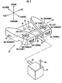
- a bipedal mobile robot A in the present embodiment is a humanoid robot comprising an upper body 1 (torso), legs 2, arms 3 and a head 4. Furthermore, FIG. 1 is a side view of the robot A, so that only one of the legs 2 and the arms 3 are described, respectively, but the legs 2 and the arms 3 are provided by a pair (two), respectively.
- the leg 2 and the arm 3 shown in FIG. 1 indicate the leg 2 and the arm 3 on the left side of the robot A facing forward.
- the upper body 1 of this robot A comprises a main body 5 having the legs 2 and the arms 3 extendedly provided therefrom and supporting a head 4, and a case-like sub body 6 attached to a rear portion of the main body 5 designed to be carried on the back of this main body 5.
- a waist 7 is formed on the lower portion of the main body 5, and each leg 2 is extendedly provided from a right/left pair of hip joints 8 provided on the waist 7, respectively.
- Each leg 2 has a knee joint 10 and an ankle joint 11 in order from the side of the hip joint 8 between its foot 9 and the hip joint 8.
- the hip joint 8 is adapted to be capable of rotary motions about three axes in an upward/downward direction, a right/left direction, and a forward/backward direction
- the knee joint 10 is adapted to be capable of a rotary motion about one axis in the right/left direction
- the ankle joint 11 is adapted to be capable of rotary motions of two axis in the forward/backward direction and the right/left direction.
- each leg 2 is adapted to be capable of performing a movement almost the same as a human leg.
- a shoulder joint 13 is provided on each side of the upper portion of the main body 5, and each arm 3 is extendedly disposed from the shoulder joint 13 on each side.
- Each arm 3 has an elbow joint 15 and a wrist joint 16 in order from the side of the shoulder joint 13 between its hand portion 14 and a shoulder joint 13.
- the shoulder joint 13, the elbow joint 15 and the wrist joint 16 are adapted to be capable of rotary motions about three axes, one axis, and one axis, respectively, and capable of making each arm 3 to perform a motion similar to a motion of a human arm.
- each joint of each leg 2 and each arm 3 are designed to be driven by an electric motor not graphically shown.
- the head 4 is supported by the upper portion of the main body 5, and an imaging device (not shown) for vision of the robot A is built in its interior portion.
- the main body 5 is mounted with a battery 17 as an electric source for a motion of the robot A.
- the sub body 6 accommodates a driver circuit unit 18 of an electric motor (not shown) for driving each joint of each leg 2 and each arm 3, a control unit 19 (hereinafter referred to as ECU 19) for taking charge of a motion control of the robot A (an operation control for each joint of the leg 2 and the arm 3), a communication system 20 for transmitting/receiving various information between the ECU 19 and a remote control device 22 to be described later, and a DC/DC converter 21 for converting an output voltage level of the battery 17 into a level such as a level for operating the ECU 19 and the like.
- the ECU 19 is configured with an electric circuit including a microcomputer or the like, and is equivalent to movement control means in the present invention.
- the communication system 20 conducts wireless communications in the present embodiment.
- a right side leg 2 may be referred to as a right leg 2R and a left side leg 2 may be referred to as a left leg 2L in a direction that the robot A faces forward.
- FIG. 2 A main configuration of the remote control device 22 of the present invention for operating a remote control of a moving action by the leg 2 of the afore-mentioned bipedal mobile robot A is shown in FIG. 2 .
- the remote control device 22 comprises a manipulator 23 that an operator (an operator of the robot A) holds to operate, and a communication system 25 connected to the manipulator 23 through a cable 24.
- the communication system 25 collaborates and mediates with the communication system 20 of the robot A to transmit/receive information between the manipulator 23 and the ECU 19 of the robot A, resulting in conducting a communication with the communication system 20 of the robot A through an antenna 25a by radio.
- the manipulator 23 comprises a plurality of manipulator levers (10) for performing an commanding operation of a moving direction and a moving amount which the robot A desires: 26L(forward); 26L(backward); 26L(left); 26L(right); 26L(turning); 26R(forward); 26R(backward); 26R(left); 26R(right); and 26L(turning)(hereinafter may be referred to as manipulator levers 26 generically, when these manipulator levers do not particularly require to be differentiated).
- the manipulator lever 26L(forward), 26R(forward) are manipulator levers for moving the robot A toward the front
- the manipulator lever 26L(backward), 26R(backward) are manipulator levers for moving the robot A toward the back
- the manipulator lever 26L(left), 26R(left) are manipulator levers for moving the robot A toward the left
- the manipulator lever 26L(right), 26R(right) are manipulator levers for moving the robot A toward the right
- 26L(turning), 26R(turning) are manipulator levers for rotating the robot A clockwise or counterclockwise.
- the manipulator levers excluding the manipulator levers 26L(turning), 26R(turning) are a button switch type, respectively, so that these manipulator levers are in an ON state only in an operated state that these manipulator levers are pressed, and in an OFF state in a normal state (a non-operation state) that these manipulator levers are not pressed.
- manipulator levers 26L(turning), 26R(turning) are dial style manipulator levers rotatably about an axis in a vertical direction in both directions of a clockwise and a counterclockwise rotations, respectively, so that these manipulator levers are energized by a spring (not shown) which is in a predetermined neutral rotational position in the normal state (non-operation state).
- manipulator levers 26L(forward), 26L(backward), 26L(left), 26L(right), and 26L(turning) are the manipulator levers for moving the left leg 2L particularly when the robot A is stopped with legs opened as will be described later.
- These manipulator levers are provided on a left side portion of the manipulator 23 facing forward.
- the manipulator levers 26L(forward), 26L(backward), 26L(left), and 26L(right) are disposed in a cross shape in four directions on a surface of a leftward portion of the manipulator 23, respectively, and the manipulator lever 26L(turning) is disposed on a front end surface portion of the leftward portion of the manipulator 23 with a portion of a periphery surface portion of the manipulator lever 26L(turning) exposed (hereinafter may be referred to as left-manipulator levers 26L generically, when the manipulator levers 26L(forward), 26L(backward), 26L(left), 26L(right), and 26L(turning) do not particularly need to be distinguished).
- manipulator levers 26R(forward), 26R(backward), 26R(left), 26R(right), and 26R(turning) other than the above-mentioned left-manipulator levers 26L are the manipulator levers for moving the right leg 2R particularly when the robot A is stopped with the legs opened as will be described later.
- manipulator levers 26R(forward), 26R(backward), 26R(left), 26R(right), and 26R(turning) are provided on a right side portion of the manipulator 23, and disposed on the surface on a rightward portion and the front edge portion of the manipulator 23 as with the left-manipulator levers 26L (hereinafter, the manipulator levers 26R(forward), 26R(backward), 26R(left), 26R(right), and 26R(turning) may be referred to as right-manipulators 26R as with the case of the left-manipulators 26L).
- each manipulator lever of the left-manipulator levers 26L and each manipulator lever of the right-manipulator levers 26R when it is not necessary to distinguish between right and left, symbols of "R” and “L” may be omitted and referred to as the manipulator levers 26(forward), 26(backward), 26(left), 26(right), and 26(turning).
- the manipulator 23 comprises a plurality of the manipulator levers 26 as described above, and further comprises a confirmation switch 27 for confirming an after-mentioned commanding operation for a moving direction and a moving amount of the robot A by the manipulator levers 26 on a center portion of a surface thereof, a cancellation switch 28 for canceling the command for the moving direction and the moving amount, an opened-legs-stop ON/OFF switch 29 for commanding whether or not to stop the robot A with the legs opened after a movement as will be described later, a liquid crystal display 30 for showing a post-movement position information indicating to which movement position the robot A moves from a current position according to the moving direction and the moving amount of the robot A determined by manipulating the manipulator levers 26, and a plurality of LED lamps 31 as information means for informing a change of the moving amount set in each moving direction (a forward/backward direction, a right/left direction, and a turning direction in the present embodiment) of the robot A corresponding to each manipulator lever 26 during the operation.
- a movement mode selecting switch 32 for selectively specifying a movement mode of the robot A depending on an operation of the manipulator 23 is provided.
- the confirmation switch 27, the cancellation switch 28, and the opened-legs-stop ON/OFF switch 29 are press-button switch type that an ON state is made by a press-operation as the same with the manipulator levers 26(forward), 26(backward), 26(left), and 26(right), and the movement mode selecting switch 32 is a two-position changer switch which may take two operating positions.
- the plurality of LED lamps 31 is provided in parallel in a right/left direction of the manipulator 23.
- a selectable movement mode by the movement mode selecting switch 32 has a minor movement mode for moving the robot A for a relatively small movement amount which can move the robot A by alternately performing a lifting/landing action for two legs 2, 2 of the robot A once at a time, and a major movement mode for moving the robot A for such a relatively large amount which may need to alternately perform the lifting/landing action for the two legs 2, 2 of the robot A for multiple times (perform the movement operation of the robot A for multiple times).
- the minor movement mode and the major movement mode are equivalent to a first movement mode and a second movement in the present invention, respectively.
- the manipulator 23 is provided with a manipulation signal generating circuit 33 for generating a signal in response to respective operation states of the aforementioned each manipulator lever 26, the confirmation switch 27, the cancellation switch 28, the opened-legs-stop ON/OFF switch 29, and the movement mode selecting switch 32, an arithmetic processing circuit 34 in which the manipulation signal is input, driving circuits 35, 36 for driving the LED lamps 31 and the liquid crystal display 30, respectively, and a communication processing circuit 37 for taking charge of transmitting/receiving signal data between the arithmetic processing circuit 34 and the communication system 25, in the interior portion thereof.
- a parenthesized reference numeral (39) regarding to the manipulator levers is a reference numeral with regard to a description of a fourth embodiment to be described later.
- the manipulation signal generating circuit 33 generates a signal for indicating whether or not these switches are in the ON state.
- the manipulation signal generating circuit 33 generates respective different signals when the manipulator lever is operated to rotate more than a predetermined amount in a clockwise direction from a neutral rotational position, and when the manipulator lever is operated to rotate more than a predetermined amount in a counterclockwise direction. In other words, a signal for indicating which direction each manipulator lever 26(turning) is operated to turn, the clockwise direction or the counterclockwise is generated.
- the arithmetic processing circuit 34 is a circuit including a CPU that executes a processing for setting a moving amount of the robot A in response to the manipulation signal input from the manipulation signal generating circuit 33 as will be described later, a processing for outputting moving instruction data which comprises the set data, data of a manipulation state for the opened-legs-stop ON/OFF switch 29 and the movement mode selecting switch 32, or the like, to the communication system 25 through the communication processing circuit 37, a processing for controlling indications of the LED lamps 31 and the liquid crystal display 30 through the driving circuits 35, 36 as will be described later. Further, this arithmetic processing circuit 34 is equivalent to moving amount setting means in the present invention.
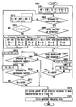
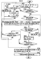
- the arithmetic processing circuit 34 of the manipulator 23 executes a processing as shown in the flowchart of FIG. 4 .
- the arithmetic processing circuit 34 is first initialized to have values for various variables NF, NB, NR, NL, NCW, NCCW, TP, and TR to be "0" in STEP 1.
- the variables NF, NB, NR, and NL are variables for counting the number of times that the manipulator levers 26(forward), the manipulator levers 26(backward), the manipulator levers 26(right), and the manipulator levers 26(left) are pressed to be operated, respectively.
- variables NCW, NCCW are variables for counting the number of times that the manipulator levers 26(turning) are operated in the clockwise direction and in the counterclockwise direction, respectively (hereinafter, the variables NF, NB, NR, NL, NCW, and NCCW are referred to as operation number variables).
- the variable TP is a variable for clocking time that one manipulator lever 26 is continuously operated (however, regarding to each manipulator 26(turning), for time that it is continuously operated in a same turning direction)
- the variable TR is a variable for clocking continuation time in a state that none of the manipulator levers 26 is operated (hereinafter, the variables TP, TR are referred to as time variables).
- the arithmetic processing circuit 34 judges whether or not any manipulator 26 is operated based on an output of the manipulation signal generating circuit 33 (STEP 2).
- the arithmetic processing circuit 34 judges which manipulator lever 26 is operated and which moving direction of the robot A this manipulator lever 26 corresponds to (STEP 3), a value for the operation number variable NF, NB, NR, NL, NCW, or NCCW corresponding to the judged direction is increased by "1" (STEP 4).
- the values of the respective time variables TP, TR are initialized to be "0".
- the value for the operation number variable NF is increased even when either of the left and right-manipulator levers 26L(forward), 26R(forward) is operated, and this is the same as where the operation number variables NB, NR, and NL are concerned.
- the value for the operation number variable NCW is increased even when either of the left and right-manipulator levers 26L(turning), 26R (turning) is operated in the clockwise direction, and this is the same as where the operation number variable NCCW is concerned.
- the arithmetic processing circuit 34 judges whether or not the operation of the manipulation levers 26 is released (STEP 5), and judges whether or not a current value for the time variable TP reaches the predetermined maximum time MAXTP when the operation of the manipulation levers 26 continues (STEP6).
- the arithmetic processing circuit 34 assumes that the operation of the manipulator 26 which the robot A has been moved up to now is cancelled, and the processing of the aforementioned STEP 1 is executed to initialize the values for the operation number variables NF, NB, NR, NL, NCW, and NCCW and the time variables TP, TR to be "0".
- the arithmetic processing circuit 34 judges whether or not the cancellation switch 28 has been operated (STEP 9).
- the arithmetic processing circuit 34 executes the initialization processing of STEP 1 in the same manner when the judgment result of STEP 6 is YES.
- the arithmetic processing circuit 34 further judges whether or not the confirmation switch 27 is operated (STEP 10).
- the arithmetic processing circuit 34 assumes that the operation of the manipulator lever 26 for moving the robot A is completed, resulting in executing a processing in STEP 16 to be mentioned later, and when the confirmation switch 27 is not operated, furthermore, the arithmetic processing circuit 34 judges whether or not a current value of the time variable TR further reaches a predetermined maximum MAXTR (STEP 11).
- a deviation Y NR-NL
- the arithmetic processing circuit 34 sets a moving amount in the forward/backward direction, a moving amount in the right/left direction, and a moving amount in a turning direction (rotating amount) of the robot A based on a predetermined data table with respect to respective variables for these values.
- the data table is particularly provided to every type of movement modes (the minor movement mode or the major movement mode) of the robot A selected by the movement mode selecting switch 32, so that the data table for this minor movement mode is used in STEP 16 in a state that the minor movement mode is selected.
- a moving amount in each direction of the robot A which is set according to the data table for the minor movement mode is a relatively small moving amount (for example, an order of centimeters) that the robot A can be moved by alternately performing a lifting/landing action for the two legs 2, 2 of the robot A once at a time.
- a moving amount in each direction of the robot A is set to a value proportional to the respective values of the corresponding number variables X, Y, and THZ.
- a moving amount in the turning direction which is set in response to the value for the turning number variable THZ is THZ>0, it is a rotational amount in the clockwise direction, and when it is THZ ⁇ 0, it is a rotational amount in the counterclockwise direction.
- the moving amount in a direction corresponding to the number variable with "0" is also "0".
- a moving amount in each direction of the forward/backward, the right/left, and the turning directions of the robot A is set in response to the values for the number variables X, Y, and THZ corresponding to these respective directions, and resultingly, the moving amount in each direction will be set depending on the operation numbers of the manipulator levers 26 corresponding to the respective directions.
- the moving amount in each direction of the robot A is set proportional to the corresponding value of the number variables X, Y, and THZ, but basically, the moving amount may be set in a manner that as absolute values for the values of the number variables X, Y, and THZ increase, the moving amounts of the corresponding directions increase.
- the degree of an increase in a moving amount may be changed depending on the degree of absolute values of the number variable X, Y, and THZ.
- the arithmetic processing circuit 34 After the amount in each direction of the forward/backward, the right/left, and the turning directions is set as noted above, the arithmetic processing circuit 34 outputs movement commanding data including setting data of the moving amount for each direction and respective operational state data of the opened-legs-stop ON/OFF switch 29 and the movement mode selecting switch 32 through the communication processing circuit 37 to the communication system 25 (STEP 17).
- the arithmetic processing circuit 34 is adapted to store data for indicating either the manipulator lever 26 first operated in the aforementioned STEP 2 is one of the left-manipulator levers 26L or one of the right-manipulator levers 26R (hereinafter referred to as right/left manipulation distinguishing data), and output the right/left manipulation distinguishing data with the movement commanding data. Additionally, at time after the output of the movement commanding data or the like is completed, or after an after-mentioned actual movement of the robot A based on the movement commanding data or the like is completed, the processing of the arithmetic processing circuit 34 goes back to "START" in FIG. 4 .
- the arithmetic processing circuit 34 of the manipulator 23 temporarily lights the LED lamps 31 depending on the value for the operation number variable NF, NB, NR, NL, NCW, or NCCW updated according to the operation.
- the LED lamps 31 are lit up in a manner that a number of the lit-up LED lamps increases from one end of a layout of the LED lamps toward the other end, as the values for respective operation number variables NF, NB, NR, NL, NCW, and NCCW increase.
- an operator can schematically recognize the operation number of the manipulator lever 26 corresponding to a desired moving direction of the robot A and then the setting value of the moving amount to the moving direction. Further, for every operation of the manipulator 26, respective values of the operation number variables NF, NB, NR, NL, NCW, and NCCW may be indicated on the liquid crystal display 30 or the like.
- the arithmetic processing circuit 34 determines a moving amount of the robot A in each direction of the forward/backward, the right/left, and the turning directions according to the data table used in the aforementioned STEP 16 depending on the forward/backward number variable X, the right/left number variable Y, and the turning number variable THZ determined according to the values for the operation number variables NF, NB, NR, NL, NCW, and NCCW.
- the arithmetic processing circuit 34 makes the liquid crystal display 30 to indicate as follows based on the determined moving amount in each direction.
- the arithmetic processing circuit 34 leads the liquid crystal display 30 to show an image G1 of coordinates with two axis for the forward/backward direction and the right/left direction having a current position of the robot A as an origin point, an image G2 showing a current position of the feet 9, 9 of the robot A, an image G3 showing a position and a direction of the feet 9, 9 after the movement of the robot A determined according to the current values for the forward/backward number variable X, the right/left number variable Y, and the turning number variable THZ, and an image G4 of numeric data showing the value of a moving amount in each direction corresponding to the current values for the forward/backward number variable X, the right/left number variable Y, and the turning number variable THZ.
- Such indications of the liquid crystal display 30 allow the operator to successively and visually confirm a position (including an orientation) of the robot A after the movement caused by the operation of the manipulator 26 performed by the operator herself/himself.
- the movement commanding data and the right/left manipulation distinguishing data which is output from the arithmetic processing circuit 34 according to the processing of the arithmetic processing circuit 34 of the manipulator 23 as described above through the communication processing circuit 37 to the communication system 25, are given from the communication system 25 through the communication system 20 of the robot A to the ECU 19 of the robot A.
- the ECU 19 generates a desired gait defining a motion pattern (walking pattern) of the legs 2, 2 of the robot A based on the given movement commanding data and the right/left manipulation distinguishing data, so that the legs 2, 2 are operated based on the desired gait so as to control the movement of the robot A.
- the opened-legs-stop ON/OFF switch 29 is in the OFF state and the movement mode selected by the movement mode selecting switch 32 is the minor movement mode, so that the desired gait generated by the ECU 19 is a desired gait in a manner that the lifting/landing action for the two legs 2, 2 is performed one at a time in turn.
- the ECU 19 basically determines the leg 2 to be lifted first in moving based on the right/left manipulation distinguishing data.
- the ECU 19 determines the right leg 2R as the leg 2 to be lifted first in moving
- the ECU 19 determines the left leg 2L as the leg 2 to be lifted first on the occasion of moving.
- the ECU 19 determines the leg 2, which exists on the same side of the indicated orientations of the movement in the right/left direction or the rotation of the turning direction, as the leg 2 to be lifted first of the two legs 2, 2.
- the right leg 2R is adapted to be the leg 2 to be lifted first
- the left leg 2L is adapted to be the leg 2 to be lifted first.
- the leg 2 to be first lifted is attempted to be determined depending on which manipulator lever 26 is first operated, the right-manipulator lever 26R or the left-manipulator lever 26L.
- the leg 2 to be first lifted may be determined depending on which manipulator lever 26 is last operated, the right-manipulator lever 26R or the left-manipulator lever 26L.
- the ECU 19 determines a relative landing position (including an orientation) with respect to the foot 9 of the leg 2 on a supporting leg side of the foot 9 of the leg 2 (the leg 2 on a free leg side) to be first lifted depending on the setting values of the moving amount for every direction of the forward/backward, the right/left, and the turning directions of the robot A.
- a landing position of the foot 9 of the leg 2 on the free leg side to be first lifted is determined to be a position moved only by the setting value for the moving amount in each direction of the forward/backward, the right/left, and the turning directions from a state that the foot 9 of the leg 2 on the free leg side is arranged in parallel with a specified space toward the side of the foot 9 of the leg 2 on the supporting leg side with the robot A in a stopped state. Furthermore, the ECU 19 determines a landing position of the foot 9 of the leg 2 to be secondly lifted as a position arranged in parallel with the above-mentioned specified space toward the side of the foot 9 of the leg 2 on the supporting leg side.
- the robot A will be moved by the moving amount set by manipulating the manipulator lever 26 of the manipulator 23.
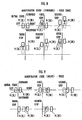
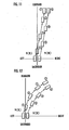
- Patterns of the movements of the robot A are exemplified in FIG. 6 (a) to FIG. 6 (d) , and FIG. 7 (a) and FIG. 7 (b) .
- Each view of these patterns illustrates movements schematically in chronological order from the left side of each view, from an initial state through a second step of the movements of the feet 9, 9 of the two legs 2, 2 in moving the robot A when the manipulator lever 26 is operated as included in the same view in the minor movement mode.
- the feet 9, 9 of the legs 2, 2 are laterally arranged in parallel with the specified space. Further, in this initial state, as previously noted, the marching-in-place action of the legs 2, 2 of the robot A may be performed.
- FIG. 6 (a) is an example when only the right-manipulator lever 26(forward) of the manipulator levers 26 is operated three times for instance.
- the variable for the forward/backward number variable X is +3, and the setting value for the moving amount of the robot A will be the moving amount corresponding to the three operations of the manipulator lever 26(forward) facing toward the front of the robot A.
- a setting value for the moving amount in the right/left and the turning directions of the robot A is "0".
- the right-manipulator 26 is first operated, so that at the first step, the foot 9 of the right leg 2R is lifted and landed on a position moved toward the front from the position of the initial state only by the setting value of the moving amount toward the front.
- the foot 9 of the left leg 2L is lifted, and landed on a position arranged with the same space as in the initial state in parallel with the foot 9 of the right leg 2R. Accordingly, toward a direction (front) in response to an operation of the manipulator lever 26, the robot A will be moved by the moving amount set by this operation.
- the movement in the forward/backward direction of the robot A as described above is performed also in the same manner, when only either one of the right-manipulator lever 26(backward) or the left-manipulator lever 26(backward) is operated.
- This one example is shown in FIG. 6 (b) .
- the movement differs from the case that only the manipulator lever 26(forward) is operated, only in one respect that the moving direction of the foot 9 of each leg 2 in the first and the second steps is the rear direction.
- FIG. 6 (b) is the example when the left-manipulator lever 26(backward) is operated three times, so that at the first step, the lifting/landing of the left leg 2L is performed.
- FIG. 6 (c) is an example when only either one of the right-manipulator lever 26(right) or the left-manipulator lever 26(right) is operated three times, for instance.
- a setting value of the moving amount of the robot A is the moving amount corresponding to the three operations of the manipulator lever 26(right) facing toward the right of the robot A, and the setting value of the moving amount in the forward/backward direction and the turning direction is "0".
- the right-manipulator lever 26(right) or the left-manipulator lever 26(right) at the first step, the right leg 2R on the same side of the direction (toward the right in this case) of the movement of the robot A is lifted, and then landed on a position moved toward the right from the position of the initial state only by the setting value of the moving amount operated by the right-manipulator lever 26(right) or the left-manipulator lever 26(right).
- the foot 9 of the left leg 2L is lifted, the foot 9 is landed on a position that the initial state is made with respect to the foot 9 of the right leg 2R as is the same as the case in FIG. 6(a) .
- the robot A is moved by the amount set by the operation. Additionally, at this point, the right leg 2R is moved at the first step, so that the robot A may be moved maintaining the stable posture without generating an interference of the two feet 9, 9. Further, when only either one of the right-manipulator lever 26(left) or the left-manipulator lever 26(left) is operated, the leg 2 lifted and landed at the first and the second steps and the direction that the leg 2 is moved are the opposite of the FIG. 6 (c) , so that only this point differs from FIG. 6 (c) .
- FIG. 6 (d) is an example when only either one of the right-manipulator lever 26(turning) or the left-manipulator lever 26(turning) is operated twice for example in the clockwise direction.
- the setting value of the moving amount of the robot A is a moving amount (rotating amount) corresponding to the two operations of the manipulator lever 26(turning) in the turning direction of the robot A toward the clockwise direction, and the setting values of the moving amount in the forward/backward direction and the right/left direction are "0".
- the foot 9 of the left leg 2L is lifted, the foot 9 is landed on a position to be in the same state as the initial state with respect to the foot 9 of the right leg 2R. Accordingly, toward the direction (clockwise direction) in response to the operation of the manipulator lever 26(turning), the robot A will be turned by the moving amount (rotating amount) set by the operation. Additionally, at this moment, the right leg 2R is moved at the first step, so that the robot A may move while maintaining a stable posture.
- FIG. 7 (a) is an example when either of the right-manipulator lever 26(forward) or the left-manipulator 26(forward) is operated three times and either of the right-manipulator lever 26(right) or the left-manipulator lever 26(right) is operated three times, for instance.
- a setting value of the moving amount of the robot A has a moving amount in the forward/backward direction and a moving amount in the right/left direction.
- the setting value of the moving amount in the forward/backward direction is the moving amount corresponding to the three operations of the manipulator lever (front) toward the front of the robot A
- the setting value of the moving amount in the right/left direction is the moving amount corresponding to the three operations of the manipulator lever (right) toward the right of the robot A.
- a setting value ( ⁇ 0) of the moving amount toward the right of the robot A is included, so that at the first step, the right leg 2R is lifted to move toward the front from the position of the initial state only by the setting value of the moving amount operated by the manipulator 26(forward), and landed on a position moved toward the right from the position of the initial state only by the setting value of the moving amount operated by the manipulator lever 26(right).
- the foot 9 of the left leg 2L is lifted, the foot 9 is landed on a position to be in the same state as the initial state with respect to the foot 9 of the right leg 2R. Accordingly, toward a direction (toward the front in a right diagonal direction in FIG.
- the movement of the robot A as described above is performed in the same way when the manipulator 26 is operated to set a moving amount in every direction of the forward/backward, the right/left, and the turning directions, for example.
- This example is shown in FIG. 7 (b) , in this example, either of the right-manipulator lever 26(forward) or the left-manipulator lever 26(forward) is operated three times and either of the right-manipulator lever 26(right) or the left-manipulator lever 26(right) is operated once, and furthermore, either of the right-manipulator lever 26(turning) or the left-manipulator lever 26(turning) is operated twice in the clockwise direction.
- the right leg 2R is lifted to move toward the front from the position of the initial state only by the setting value of the moving amount operated by the manipulator 26(forward) and move toward the right from the position of the initial state only by the setting value of the moving amount operated by the manipulator 26(right), and landed on a position turned toward the clockwise direction from the position of the initial state only by the setting value of the moving amount (rotating amount in the clockwise direction) operated by the manipulator lever 26(turning).
- the foot 9 of the left leg 2L is lifted, the foot 9 is landed on a position to be in the same state as the initial state with respect to the foot 9 of the right leg 2R.
- the robot A will be moved by the moving amount that these moving amounts are combined.
- the manipulator lever 26(forward) and the manipulator lever 26(turning) are operated three times and twice, respectively, so that a moving amount in the forward/backward direction and a moving amount (rotating amount) in the turning direction of the robot A are the same as the conditions in FIG. 6 (a) and FIG. 6 (b) , respectively.
- the manipulator lever 26(right) is operated once, so that a moving amount in the right/left direction is less than the amount of the condition (the number of operations is three) in FIG. 6 (c) .
- the two legs 2, 2 are lifted and landed once at a time in turn.
- the foot 9 of the leg 2 to be lifted and landed is moved in the forward/backward, the right/left, and the turning directions only by the moving amounts set by operating the manipulator levers 26 of the manipulator 23, and at the second step, the two legs 2 are arranged in parallel, so that the robot A will be moved by a desired moving amount in a desired direction. Accordingly, the robot A may surely be moved by a relatively small moving amount to a desired position.
- a moving amount toward each direction may be set by a simple operation of the manipulator lever 26.
- the leg to be moved at the first step in moving in the forward/backward direction (such as the movements in FIG. 6 (a), FIG. 6 (b) ), the leg to be moved at the first step is adapted to be determined by which manipulator lever 26 of the manipulator 23 is operated first, the right-manipulator lever 26R or the left-manipulator lever 26L.
- the minor movement mode but, in the OFF state of the opened-legs-stop ON/OFF switch 28
- only the final moving position of the robot A matters, so that basically, the leg to be moved at the first step may be either of the two legs 2.
- each leg 2 is determined to be lifted/landed at predetermined timing in synchronization with a predetermined clock, and when a moving amount is set by the manipulator 23 just before the lifting timing of the left leg 2L, the left leg 2L may be moved at the first step, or when the moving amount is set just before the lifting timing of the right leg 2R, the right leg 2R may be moved at the first step.
- the ECU 19 allows only one of the legs 2, 2 to perform a lifting/landing action only once, and after the lifting/landing action, a landed state of the two legs 2, 2 is maintained.
- the foot 9 of the leg 2 performing the lifting/landing action is moved in each direction of the forward/backward, the right/left, and the turning directions according to the moving amounts set by the manipulator 23 in an analogous fashion with the first step in the minor movement mode.
- the leg 2 performing the lifting/landing action is adapted to be the right leg 2R, and when that is the left-manipulator lever 26, the leg 2 performing the lifting/landing action is adapted to be the left leg 2L.
- the major movement mode is selected as a movement mode of the robot A by the movement mode selecting switch 32.
- a basic processing description of the arithmetic processing circuit 34 of the manipulator 23 in the major movement mode is the same as that in the minor movement mode, and executed in the procedure as shown in the flowchart in FIG. 4 .
- the data table to be referred to in setting the moving amounts in the forward/backward, the right/left, and the turning directions of the robot A in STEP 16 of FIG. 4 is a data table for the major movement mode.
- the major movement mode is a mode for moving the robot A by a relatively large moving amount in such a manner that the lifting/landing action for the two legs 2 of the robot A needs to alternately be performed multiple times (the moving action of the robot A is performed for multiple steps) as previously described.
- the respective moving amounts in the forward/backward, the right/left, and the turning directions corresponding to the respective values for the forward/backward number variable X, right/left number variable Y, and turning number variable THZ are larger than those in the minor movement mode, for example, the order of several meters.
- the moving amount in each direction is set to a value proportional to the corresponding respective values for the number variable X, Y, and THZ as in the minor movement mode.
- the ECU 19 of the robot A determines a number of walking steps of the robot A and generates a desired gait of the legs 2, 2 of the robot A for each step based on the movement commanding data given from the manipulator 23 as previously described, thereby controlling the movement of the robot A by moving the legs 2, 2 of the robot A based on the desired gait.
- the ECU 19 determines the number of walking steps to the target position defined according to the setting value of the moving amount based on a map or the like predetermined in consideration of ensuring stability while the robot A is moving, according to the setting values of the moving amounts in each direction of the forward/backward, the right/left, and the turning directions which the movement commanding data shows. Furthermore, the ECU 19 determines the moving amount toward each direction for each step of the robot A according to the determined number of walking steps and the setting value of the moving amount in each direction, so that the target gait for each step is generated based on this moving amount.
- the target gait is generated in such a manner that the foot 9 of the leg 2 on the free leg side is arranged to be in parallel in the right/left direction with a predetermined space with respect to the foot 9 of the leg 2 on the supporting leg side as at the second step in the minor movement mode.
- the leg 2 to be moved at the first step may basically be either of the two legs 2, 2, the right leg or the left leg.
- the leg 2 may be determined depending on which manipulator lever 26 is operated first by the manipulator 23, the right manipulator 26 or the left manipulator 26 (this is ascertained according to the right/left manipulation distinguishing data).
- the leg 2 to be moved at the first step may be determined depending on which manipulator lever 26 is operated last by the manipulator 23, the right-manipulator lever 26 or the left-manipulator lever 26.
- FIG. 8 to FIG. 12 An embodiment of the movement of the robot A in this situation is exemplified in FIG. 8 to FIG. 12 .
- FIG. 8 to FIG. 12 An embodiment of the movement of the robot A in this situation is exemplified in FIG. 8 to FIG. 12 .
- Each view of these drawings schematically in a time series order describes the movement for each step from the initial state of the feet 9, 9 of the two legs 2, 2 (a condition that the feet 9, 9 are arranged side by side in a line with a predetermined space) in moving the robot A when the manipulator 26 is operated in the major movement mode as included in each view.
- FIG. 8 shows an example in the case of operating only the manipulator lever 26 (forward) relating to the movement of the robot A toward the front four times, for instance.
- a setting value of a moving amount of the robot A in this situation is for a moving amount corresponding to the four operations of the manipulator lever 26(forward) toward the front of the robot A, and the setting values of the moving amounts in the right/left, and the turning directions are "0".
- a number of walking steps to be needed for the movement of the robot A is set to be 5, for example.
- the foot 9 of the leg 2 on a free leg side is landed on a position where this foot is forwardly moved by a predetermined amount in response to the setting value of the moving amount toward the front to the foot 9 of the leg 2 on a supporting leg side.
- the foot 9 of the leg 2 on the free leg side (the left leg 2L in the example of FIG. 8 ) is landed on a position to be in parallel with predetermined distance with respect to the foot 9 of the leg 2 on the supporting leg (the right leg 2R in the example of FIG. 8 ), so that both the feet 9, 9 will be in a state that is the same as the initial state.
- the robot A will be moved by an amount set by this operation. Further, when only the manipulator lever 26(back) is operated, an action of the leg 2 of the robot A is performed in the same manner in FIG. 8 , except that the foot 9 of the leg 2 on the free leg side at each step is moved backward, in a manner opposite to FIG. 8 .
- FIG. 9 shows an example in the case of operating only the manipulator lever 26(right) relating to the movement of the robot A toward the right twice, for instance.
- a setting value of a moving amount of the robot A in this situation is for a moving amount corresponding to the two operations of the manipulator lever 26(right) toward the right, and the setting values of the moving amounts in the forward/backward, and the turning directions are "0".
- a number of walking steps to be needed for the movement of the robot A is set to be 4, for example.
- the right leg 2R on the same side of a direction that the robot A is moved toward (toward the right) is taken as a free leg, and the foot 9 of the right leg 2R is landed on a position where this foot is moved rightward by a predetermined amount in response to the setting value of the moving amount.
- the left leg 2L is taken as the free leg and landed on a position where the foot 9 of the left leg 2L and the foot 9 of the right leg 2R on the supporting leg side are arranged in parallel with the same predetermined space as that in the initial state.
- the robot A will be moved by the moving amount set by this operation. Further, when only the manipulator lever 26(left) is operated, the foot 9 of the left leg 2L is moved toward the left at odd numbered steps in a manner opposite to FIG. 9 , and at even numbered steps, the foot 9 of the right leg 2R is arranged in parallel to the foot 9 of the left leg 2L in a state that is the same as the initial state.
- FIG. 10 shows an example in the case of operating only the manipulator lever 26(turning) relating to the turning of the robot A in the counterclockwise direction twice, for instance.
- a setting value of a moving amount of the robot A in this situation is for a rotating amount corresponding to the two operations of the manipulator lever 26(turning) toward the counterclockwise direction, and the setting values of the moving amounts in the forward/backward, and the right/left directions are "0".
- a number of walking steps to be needed for the movement of the robot A is set to be 4, for example.
- the left leg 2L on the same side of a direction that the robot A is turned toward (toward the counterclockwise direction) is taken as a free leg, and the foot 9 of the left leg 2L is landed on a position where this foot is turned toward the counterclockwise direction by a predetermined amount in response to the setting value of the moving amount (rotating amount).
- the right leg 2R is taken as the free leg and landed on a position where the foot 9 of the right leg 2R and the foot 9 of the left leg 2L on the supporting leg side are arranged in parallel with the same predetermined space as that in the initial state.
- the robot A will be turned by the moving amount (rotating amount) set by this operation.
- the foot 9 of the right leg 2R is turned toward the clockwise direction at odd numbered steps in a manner opposite to FIG. 10 , and at even numbered steps, the foot 9 of the left leg 2L is arranged in parallel to the foot 9 of the right leg 2R in a state that is the same as the initial state.
- FIG. 8 to FIG. 10 described above show examples in the cases of operating the manipulator lever 26 in only one direction of the forward/backward, the right/left, and the turning directions, respectively.
- the robot A may also be moved in a manner that the movements in the respective directions are combined.
- FIGs. 11 and 12 show an example in the case of operating the manipulator lever 26(forward) six times and operating the manipulator lever 26(right) twice.
- a numeral in a circle in FIG. 11 indicates a number of walking steps.
- setting values of moving amounts of the robot A are for the moving amount in the forward/backward direction and the moving amount in the right/left direction.
- the setting value of the moving amount in the forward/backward direction is for the moving amount in response to the six operations of the manipulator lever 26(forward) toward the front of the robot A
- the setting value of the moving amount in the right/left direction is for the moving amount in response to the two operations of the manipulator lever 26(right) toward the right of the robot A.
- a number of walking steps to be needed for the movement of the robot A is set to be 7, for example.
- the leg 2 on a free leg side is landed on a position where this leg is moved toward the front by a predetermined amount in response to the setting value of the moving amount toward the front to the leg 2 on a supporting leg side, and this leg is moved toward the right by a predetermined amount in response to the setting value of the moving amount toward the right to the leg 2 on a supporting leg side.
- the foot 9 of the leg 2 on the free leg side (the left leg 2L in the example of FIG. 11 ) is landed on a position where the foot 9 of the leg 2 on the supporting leg (the right leg 2R in the example of FIG.
- the robot A is arranged in parallel with a predetermined space inbetween, so that both the feet 9, 9 will be in a state that is the same as the initial state. Accordingly, toward a direction (toward the front in a right diagonal direction in FIG. 11 ) determined according to the respective moving amounts in the forward/backward, and the right/left directions by operating the manipulator lever 26(forward) and the manipulator lever 26(right), the robot A will be moved by the moving amount that these moving amounts are combined.
- FIG. 12 shows an example in the case of operating the manipulator lever 26(forward) four times, operating the manipulator lever 26(right) three times, and also operating the manipulator lever 26(turning) in the clockwise direction once, for instance.
- a numeral in a circle in FIG. 12 indicates a number of walking steps.
- setting values of moving amounts of the robot A are for moving amounts in all the directions of the forward/backward, the right/left, and the turning directions.
- the setting value of the moving amount in the forward/backward direction is for the moving amount in response to the four operations of the manipulator lever 26(forward) toward the front of the robot A
- the setting value of the moving amount in the right/left direction is for the moving amount in response to the three operations of the manipulator lever 26(right) toward the right of the robot A
- the setting value of the moving amount in the turning direction is for the moving amount in response to the one operation of the manipulator lever 26(turning) toward the clockwise direction.
- a number of walking steps to be needed for the movement of the robot A is set to be 7, for example.
- the leg 2 on a free leg side is landed on a position where this leg is moved toward the front by a predetermined amount in response to the setting value of the moving amount toward the front to the leg 2 on a supporting leg side, this leg is moved toward the right by a predetermined amount in response to the setting value of the moving amount toward the right to the leg 2 on a supporting leg side, and this leg is turned toward the clockwise direction by a predetermined amount in response to the setting value of the moving amount toward the clockwise direction.
- the foot 9 of the leg 2 on the free leg side (the left leg 2L in the example of FIG.
- the robot A is landed on a position where the foot 9 of the leg 2 on the supporting leg (the right leg 2R in the example of FIG. 12 ) is arranged in parallel with a predetermined gap inbetween, so that both the feet 9, 9 will be in a state that is the same as the initial state. Consequently, toward a direction determined according to the respective moving amounts in the forward/backward, the right/left, and the turning directions by operating the manipulator lever 26(forward), the manipulator lever 26(right), and the manipulator lever 26(turning), the robot A will be moved by the moving amount that these moving amounts are combined.
- the lifting/landing of the two legs 2, 2 of the robot A is performed for multiple steps, thereby allowing the robot A to be moved by a relatively large desired amount in a desired moving direction.
- a relatively simple operation of the manipulator lever 26 may set a moving amount of the robot A in each direction.
- the robot A may be stopped with the two feet 9, 9 opened (for example, in a state at the sixth step in FIGs. 11 and 12 ) just like the case of the minor movement mode.
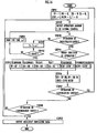
- FIG. 13 a second embodiment of the present invention is described. Further, the present embodiment is different from the first embodiment only in processing of the arithmetic processing circuit 34 of the manipulator 23, so that the present embodiment is described using the same reference numbers with the first embodiment, and descriptions for configurations and actuations which are the same as those in the first embodiment are omitted.
- the arithmetic processing circuit 34 of the manipulator 23 executes a processing as shown in the flowchart in FIG. 13 .
- the arithmetic processing circuit 34 initializes values for various variables TF, TB, TR, TL, TCW, TCCW, and T to be "0" in STEP 21.
- the variables TF, TB, TR, and TL are the respective variables for clocking the time that the manipulator lever 26(forward), the manipulator lever 26(back), the manipulator lever 26(right), and the manipulator lever 26(left) are continuously pressed to be operated.
- variables TCW and TCCW are the respective variables for clocking the time that the manipulator lever 26(turning) is continuously operated in the clockwise direction and the counterclockwise direction (hereinafter, the variables TF, TB, TR, TL, TCW, and TCCW are referred to as operation time variables).
- the variable T is the variable for clocking a duration in a state that none of the manipulator levers 26 is operated (hereinafter, the variable T is referred to as a non-operation time variable).
- the arithmetic processing circuit 34 judges whether or not any of the manipulator levers 26 is operated based on an output of the manipulation signal generating circuit 33 (STEP 22). Furthermore, when any of the manipulator levers 26 is operated, the arithmetic processing circuit 34 judges which of the moving direction of the robot A the corresponding manipulator lever 26 is operated toward (STEP 23), and the value for the operation time variables TF, TB, TR, TL, TCW, or TCCW corresponding to the judged direction increases by "1" (STEP 24). Further, in STEP 24, the value for the operation time variable TF increases even when either of the left-manipulator levers 26L(turning) and right-manipulator levers 26R(turning) is operated.
- the arithmetic processing circuit 34 judges whether or not the operation of the manipulator lever 26 is released (STEP 25). At this point, when the operation of the manipulator lever 26 is continued, after waiting for the time of the predetermined specific time width ⁇ T (STEP 26), the arithmetic processing circuit 34 returns to the processing in STEP 23 and STEP 24, and the value for the operation time variable TF, TB, TR, TL, TCW, or TCCW is increased by "1". In this manner, as long as the operation of the manipulator lever 26 continues, for each abovementioned time width ⁇ T, the value for the operation time variable TF, TB, TR, TL, TCW, or TCCW in response to the operation is increased by "1". Therefore, each value for the operation time variables TF, TB, TR, TL, TCW, and TCCW will show the time that the manipulator lever 26 is continuously operated corresponding to each direction.
- the arithmetic processing circuit 34 judges whether or not the confirmation switch 27 is operated (STEP 28). At this point, when the operation of the confirmation switch 27 is confirmed, the arithmetic processing circuit 34 executes an after-mentioned processing in STEP 35 assuming that the operation of the manipulator lever 26 for moving the robot A is completed, and when the confirmation switch 27 is not operated, additionally, the arithmetic processing circuit 34 judges whether or not the cancellation switch 28 is operated (STEP 29). When the cancellation switch 28 is operated, the arithmetic processing circuit 34 returns to STEP 21 and executes the initialization processing.
- the arithmetic processing circuit 34 executes the judgment processing of STEP 22 (a processing for judging whether or not the manipulator lever 26 is operated) after waiting for the time of the predetermined time width ⁇ T (STEP 30).
- the arithmetic processing circuit 34 judges whether or not this value for the non-operation time variable T reached the predetermined maximum value MAXT (STEP 34). At this point, when T ⁇ MAXT is given, the arithmetic processing circuit 34 executes the judgment processing of STEP 22, again after waiting for the time of the time width ⁇ T in the aforementioned STEP 30.
- the arithmetic processing circuit 34 sets the moving amount in the forward/backward direction, the moving amount in the right/left direction, and the moving amount (rotating amount) in the turning direction of the robot A, respectively, based on the predetermined data table for each variable.
- the above data table is individually provided for each type of the movement modes of the robot A (the minor movement mode or the major movement mode) selected by the movement mode selecting switch 32, resulting in using the data table depending on respective movement modes.
- the moving amount in each direction of the robot A set according to the data table for the minor movement mode is a relatively small moving amount which may move the robot A by alternately performing the lifting/landing action for the two legs 2, 2 of the robot A once at a time.
- the moving amount in each direction of the robot A set according to the data table for the major movement mode is a relatively large moving amount which may need to alternately perform the lifting/landing action for the two legs 2 of the robot A multiple times (performing the moving action of the robot A multiple steps).
- the moving amount in each direction of the robot A is set to a value proportional to the values for the time variables TX, TY, and TTHZ corresponding to the respective moving amounts.
- the moving amount in a direction corresponding to this time variable of "0" is also "0".
- a relationship between each of the time variables TX, TY, and TTHZ, and the moving amount in each movement mode does not always need to satisfy proportionality, and basically, setting may be made as absolute values for the time variables TX, TY, and TTHZ increases, the moving amount in the corresponding direction increases.
- the moving amount in each direction of the forward/backward, the right/left, and the turning directions of the robot A is set according to the individual data table for each movement mode depending on the values for the time variables TX, TY, and TTHZ corresponding to the respective directions, so that the moving amount in each direction will be set depending on the continuous operation time of the manipulator lever 26 corresponding to the respective directions for each movement mode.
- the operation time of this manipulator lever 26 will be a cumulative operation time.
- the arithmetic processing circuit 34 After the moving amount in each direction of the forward/backward, the right/left, and the turning directions is set as described above, the arithmetic processing circuit 34 outputs the movement commanding data including the setting data for the moving amount for each direction and the data for the respective operation states of the opened-legs-stop ON/OFF switch 29 and the movement mode selecting switch 32 through the communication processing circuit 37, the communication system 25, and the communication system 20 of the robot A to the ECU 19 of the robot A (STEP 36). Accordingly, the processing of the arithmetic processing circuit 34 is completed.
- right/left manipulation distinguishing data showing which manipulator lever 26 is operated first (or last) the left-manipulator lever 26L or the right-manipulator lever 26R is output with the movement commanding data from the arithmetic processing circuit 34 of the manipulator 23 to the ECU 19 of the robot A. Consequently, in moving the robot A, a data description output from the arithmetic processing circuit 34 of the manipulator 23 to the ECU 19 of the robot A is the same as that of the first embodiment.
- the arithmetic processing circuit 34 of the manipulator 23 lights the LED lamps 31 in response to the value for the operation time variables TF, TB, TR, TL, TCW, or TCCW updated by this operation.
- the LED lamps 31 are lighted in a manner that as the value for each of the operation time variables TF, TB, TR, TL, TCW, and TCCW increases by the predetermined amount, a lighting number of the LED lamps 31 increases from one side toward the other side of an arrangement of the LED lamps 31.
- the operator may operate the manipulator lever 26 while visually recognizing the operation time of the manipulator lever 26 corresponding to a desired moving direction of the robot A, and then a change of the setting value for the moving amount to the moving direction. Further, the values for the operation time variables TF, TB, TR, TL, TCW, and TCCW showing the operation time of the manipulator lever 26 for each direction may be indicated by the liquid crystal display 30 or the like.
- the arithmetic processing circuit 34 determines the moving amount of the robot A in each direction of the forward/backward, the right/left, and the turning directions according to the data table used in the above STEP 35.
- the arithmetic processing circuit 34 allows the indication of the liquid crystal display 30 (refer to FIG. 5 ) based on the determined moving amount in each direction just as in the first embodiment. Accordingly, the operator will successively and visually confirm the position (including a direction) after the movement of the robot A by operating the manipulator lever 26 by herself/himself.
- the processing described above is the processing of the arithmetic processing circuit 34 of the manipulator 23 in the present embodiment.
- the ECU 19 executes the motion control of the legs 2, 2 of the robot A in the minor movement mode (including the control for stopping the legs opened), and the motion control of the legs 2, 2 of the robot A in the major movement mode just like the first embodiment. Consequently, also in the present embodiment, a relatively simple operation of the manipulator 23 allows the robot A to move in a desired direction to a desired position. In this situation, in the minor movement mode, the robot A may be moved to the desired position by a relatively small moving amount, and in the major movement mode, the robot A may be moved to the desired position by a relatively large moving amount.
- the present embodiment differs from the first embodiment only in a portion of configuration of the manipulator and the processing of the arithmetic processing circuit 34, so that descriptions about configurations and operations, which are same as those in the first embodiment, are omitted while the same component portions or function portions are described using the same reference numbers.
- the manipulator 23 is provided with a sliding control 38 slidable in a backward/forward direction as shown on a side portion of the manipulator 23 with an arrow y, in addition to the configuration described in the first embodiment.
- This sliding control 38 is for setting the moving amount in each direction of the forward/backward, the right/left, and the turning directions of the robot A, and a manipulation amount (sliding amount) is increased from a position on a backward side (a min position shown) to a forward side in order to deal with increasing the moving amount of the robot A.
- the sliding control 38 is in a volume control style, and can be held in any slid position within the slidable range (a range from the min position to a max position shown).
- a structural configuration of the manipulator 23 in the present embodiment is same as that in the first embodiment except the above sliding control 38.
- an internal circuit of the manipulator 23 of the present invention shown in FIG. 15 comprises a manipulation signal generating circuit 33, an arithmetic processing circuit 34, a communication processing circuit 37, a driving circuits 35 of LED lamps 31, and a driving circuits 36 of a liquid crystal display 30, as in the first embodiment.
- the manipulation signal generating circuit 33 in the present embodiment is adapted to output signals for operation states of the manipulator levers 26, the confirmation switch 27, the cancellation switch 28, the opened-legs-stop ON/OFF switch 29, and the movement mode selecting switch 32 to the arithmetic processing circuit 34, and in addition to these, further outputs a signal for showing the manipulation amount of the sliding control 38 to the arithmetic processing circuit 34.
- sliding control 38 in the present embodiment is equivalent to a second manipulator lever in the third aspect of the present invention
- manipulator lever 26 is equivalent to a first manipulator lever in the third aspect in the present invention
- sliding control 38 is employed as the second manipulator lever, but a dial style control such as the manipulator lever 26(turning) for turning may also be employed.
- the arithmetic processing circuit 34 of the manipulator 23 executes a processing as shown in a flowchart of FIG. 16 .
- the arithmetic processing circuit 34 initializes a value for each kind of variables DF, DB, DR, DL, DCW, DCCW, and T to be "0" in STEP 41.
- the variables DF, DB, DR, DL, DCW, and DCCW are variables expressing setting values for moving amounts in the forward, backward, right, left, clockwise, and counterclockwise directions of the robot A (hereinafter refereed to as a moving amount variable).
- the variable T is a non-operation time variable for clocking a duration in a state that none of manipulator levers 26 is operated.
- the arithmetic processing circuit 34 detects a current manipulation amount S of the sliding control 38 based on an output of the manipulation signal generating circuit 33 (STEP 42).
- the sliding control 38 is slid by only an amount corresponding to the desired moving amount from the min position toward the max position side in FIG. 14 , and in this state, the manipulator lever 26 corresponding to the desired moving direction is operated.
- the operator wants to move the robot A forward by a predetermined amount
- the operator operates either the manipulator lever 26R(forward) or the manipulator lever 26L(forward).
- the manipulation amount S of the sliding control 38 that the arithmetic processing circuit 34 detects in the above STEP 42 is the manipulation amount of the sliding control 38 that the operator operates as described above.
- the arithmetic processing circuit 34 judges whether or not any of manipulator levers 26 is operated based on the output of the manipulation signal generating circuit 33 (STEP 43). When any of the manipulator levers 26 is operated, the arithmetic processing circuit 34 judges which of the moving directions of the robot A the corresponding manipulator lever 26 is operated (STEP 44), and sets the value for the moving amount variable DF, DB, DR, DL, DCW, or DCCW corresponding to the judged direction to a value that the manipulation amount S of the sliding control 38 detected in STEP 42 is multiplied by a gain predetermined in each direction GF, GB, GR, GL, GCW, or GCCW (STEP 45).
- the gains GF, GB, GR, GL, GCW, and GCCW may be individual values, but in the present embodiment, the gains GF and GB corresponding to the forward direction and the backward direction, respectively are set to the same value, the gains GR and GL corresponding to the rightward direction and the leftward direction, respectively are set to the same value, and the gains GCW and GCCW corresponding to the clockwise direction and the counterclockwise direction, respectively are set to the same value.
- the gains GF, GB, GR, GL, GCW, and GCCW are individually determined for each movement mode (the minor movement mode and the major movement mode) set by the movement mode selecting switch 32, and the gains are set to relatively small values in the minor movement mode and relatively large values in the major movement mode depending on a scale of the moving amount of the robot A in each movement mode.
- Such a processing in STEP 45 allows the moving amount of the robot A depending on the manipulation amount S of the sliding control 38 to be set for each direction of the forward, backward, rightward, leftward, clockwise, and counterclockwise directions. Additionally, the moving amount set at this point will be individually set depending on which movement mode is selected, the major movement mode or the minor movement mode.
- deviations DX, DY, and DTHZ indicates setting values of overall moving amounts of the robot A in the forward/backward direction, the right/left direction, and the turning direction, respectively (hereinafter, the deviations DX, DY, and DTHZ are referred to as a forward/backward moving amount variable DX, a right/left moving amount variable DY, and a turning moving amount variable DTHZ, respectively).
- the arithmetic processing circuit 34 judges whether or not the cancellation switch 28 is operated (STEP 47).
- the arithmetic processing circuit 34 executes the initialization processing of the aforementioned STEP 41.
- the arithmetic processing circuit 34 judges whether or not the confirmation switch 27 is operated (STEP 48).
- the arithmetic processing circuit 34 executes an after-mentioned processing of STEP 52 assuming that the operation of the manipulator lever 26 for moving the robot A is completed.
- the arithmetic processing circuit 34 returns to the processing of STEP 42 and detects the manipulation amount S of the sliding control 38.
- the arithmetic processing circuit 34 judges whether or not the value for the non-operation time variable T has reached a predetermined maximum time MAXT (STEP 50).
- the arithmetic processing circuit 34 waits for the time of the time width ⁇ T (STEP 51), and subsequently executes the judgment processing of the aforementioned STEP 43 (the processing for judging whether or not the manipulator lever 26 is operated).
- the arithmetic processing circuit 34 considers values for the current forward/backward moving amount variable DX, right/left moving amount variable DY, and turning moving amount variable DTHZ as setting values of final moving amounts of the robot A in the forward/backward direction, the right/left direction, and the turning direction, respectively, and outputs the movement commanding data including the setting data and the data of the respective operating states of the opened-legs-stop ON/OFF switch 29 and the movement mode selecting switch 32 through the communication processing circuit 37, the communication system 25, and the communication system 20 of the robot A to the ECU 19 of the robot A. Accordingly, the processing of the arithmetic processing circuit 34 is completed.
- the right/left manipulation distinguishing data indicating which manipulator lever 26 is operated first (or last), the left-manipulator lever 26L or the right-manipulator lever 26R is also output with the movement commanding data from the arithmetic processing circuit 34 of the manipulator 23 to the ECU 19 of the robot A. Consequently, in moving the robot A, a data description output from the arithmetic processing circuit 34 of the manipulator 23 to the ECU 19 of the robot A is identical to that of the first embodiment.
- the processing of the arithmetic processing circuit 34 returns to "START" of FIG. 16 .
- the processing of the arithmetic processing circuit 34 as has been described allows the operator to set the moving amount of the robot A depending on the manipulation amount of the sliding control 38 by operating the sliding control 38 and the manipulator lever 26 in the corresponding direction in turn for each desired direction of the robot A.
- the setting value for the moving amount in each direction will be proportional to the manipulation amount of the sliding control 38, but do not need to satisfy this proportionality, and may be set in such a manner that basically, as the manipulation amount of the sliding control 38 increases, the setting value for the moving amount in each direction increases.
- the setting value for the moving amount with respect to the manipulation amount of the sliding control 38 may also be set according to the data table in each movement mode as in the first or the second embodiment.
- the arithmetic processing circuit 34 of the manipulator 23 lights the LED lamps 31 depending on its manipulation amount.
- the LED lamps 31 are lighted in a manner that as the manipulation amount of the sliding control 38 increases by a predetermined amount, a lighting number of the LED lamps 31 increases from one side toward the other side of an arrangement of the LED lamps 31. Accordingly, the operator may operate the manipulator lever 26 while visually recognizing the manipulation amount of the sliding control 38 as well as a change of the setting value for the moving amount of the robot A corresponding to this manipulation amount.
- the arithmetic processing circuit 34 allows the indication of the liquid crystal display 30 (refer to FIG. 5 ) based on the moving amount in each direction determined according to the values of these variables DX, DY, and DTHZ just as in the first embodiment. Accordingly, the operator may successively and visually confirm the position (including a direction) after the movement of the robot A by operating the sliding control 38 and the manipulator lever 26 by herself/himself.
- the processing as has been described is the processing of the arithmetic processing circuit 34 of the manipulator 23 in the present embodiment.
- the ECU 19 executes the motion control of the legs 2, 2 of the robot A in the minor movement mode (including the control for stopping the legs opened), and the motion control of the legs 2, 2 of the robot A in the major movement mode just as in the first embodiment. Consequently, also in the present embodiment, a relatively simple operation of the manipulator 23 allows the robot A to be moved in a desired direction to a desired position. In this situation, in the minor movement mode, the robot A may be moved to the desired position by a relatively small moving amount, and in the major movement mode, the robot A may be moved to the desired position by a relatively large moving amount.
- the processing in the same manner when the confirmation switch 27 is confirmed is adapted to be executed, but, the processing in the same manner when the cancellation switch 28 is operated may also be executed.
- the present embodiment is another embodiment of the first embodiment of the present invention. Further, the present embodiment differs from the first embodiment only in a portion of configuration of the manipulator, so that descriptions about configurations and actuations, which are same as those in the first embodiment, are omitted while the same component portions or function portions are described using the same reference numbers.
- the manipulator 23 of the present embodiment is provided with the manipulator levers 39R and 39L in a joystick shape instead of the right-manipulator lever 26R and the left-manipulator lever 26L according to the first embodiment, and the respective manipulator levers 39R and 39L are disposed on a rightward place and a leftward place on a surface portion of the manipulator 23 (according to the following description, the manipulator levers 39R and 39L may generically be refereed to as the manipulator levers 39).
- each manipulator lever 39 is provided in an extended condition on a top surface portion of a sphere 40 which is pivotably provided inside the manipulator 23, and the sphere 40 is rolled, so that as shown with arrows P, Q, and R, swinging in the forward/backward direction, swinging in the right/left direction, and rotating about an axis in a vertical direction (rotations in the clockwise direction and the counterclockwise direction) are possible.
- each manipulator lever 39 is stood up in the vertical direction with a spring that is not shown, and energized in a neutral posture condition in a manner that a mark 41 marked on a periphery on each top surface portion faces forward.
- an operation for swinging the manipulator lever 39R on the right side toward the front or the back for more than a predetermined amount is equivalent to the operation of the right-manipulator lever 26(forward) or the right-manipulator lever 26(backward) in the first embodiment, respectively, thereby corresponding to the movement toward the front and the movement toward the back of the robot A, respectively.
- an operation for swinging the manipulator lever 39R toward the right or the left for more than a predetermined amount is equivalent to the operation of the right-manipulator lever 26(right) or the right-manipulator lever 26(left) in the first embodiment, respectively, thereby corresponding to the movement toward the right and the movement toward the left of the robot A, respectively.
- a operation for rotating the manipulator lever 39R toward the clockwise direction or the counterclockwise direction for more than a predetermined amount is equivalent to the operation of the right-manipulator lever 26(turning) in the clockwise direction or the counterclockwise direction in the first embodiment, respectively, thereby corresponding to the turning movement in the clockwise direction and the turning movement in the counterclockwise direction of the robot A, respectively.
- the manipulator lever 39L on the left side is also operated in the same fashion.
- the present embodiment further has a real time mode for executing the movement of the robot A almost in real time in response to the operation of the manipulator lever 39 of the robot A, so that the movement mode selecting switch 32 provided in the manipulator 23 of the present embodiment in order to alternatively select these movement modes is configured with three-position switch switchable to three types of operating positions corresponding to three types of movement modes.
- the manipulation signal generating circuit 33 in the internal circuit of the manipulator 23 (refer to FIG. 3 ), the manipulation signal generating circuit 33 generates a signal indicating the manipulation amount in each direction of the forward/backward direction, the right/left direction, and the rotating direction about an axis of each manipulator lever 39, and outputs thereof to the arithmetic processing circuit 34. According to this signal, the arithmetic processing circuit 34 recognizes which direction of the forward, backward, rightward, leftward, clockwise, and counterclockwise directions each manipulator lever 39 is operated in.
- actuations in the minor movement mode and the major movement mode are just the same as those in the first embodiment, except a point that an operating method of the manipulator lever 39 of the manipulator 23 corresponding to each moving direction of the robot A differs from that of the first embodiment. Consequently, also in the present embodiment, a relatively simple operation of the manipulator lever 39 allows the robot A to be moved in a desired position.
- the robot A in the real time mode, the robot A is moved almost in real time in response to the operation of the manipulator lever 39.
- the present applicant describes in detail in Japanese Patent Application No. 2000-351753 or PCT International Publication Number WO 02/40227 , and additionally, this is not a part of a main subject of the present invention, so that a detailed description is omitted herein, but its summary is as follows.
- the legs 2, 2 of the robot A alternately perform the lifting/landing action at a timing synchronized with a predetermined clock.
- a relative moving amount and a moving direction of the foot 9 of the left leg 2L to the foot 9 of the right leg 2R is determined depending on the manipulation amount and the operating direction (including a rotating direction) of the manipulator lever 39L just before the lifting of the left leg 2L, and the foot 9 of the left leg 2L is landed on a position of this determined moving amount and moving direction.
- a relative moving amount and moving direction of the foot 9 of the right leg 2R with respect to the foot 9 of the left leg 2L is determined depending on the manipulation amount and the operating direction (including the rotating direction) of the manipulator lever 39R just before the lifting of the right leg 2R, and the foot 9 of the right leg 2R is landed on a position of this determined moving amount and moving direction.
- the first aspect of the present invention has been taken as an example and described, but a manipulator lever in a joystick shape may certainly be applied to the second aspect or the third aspect of the present invention.
- the manipulator 23 described in the fourth embodiment instead of the manipulator 23 of the second embodiment may be used, and when applied to the third aspect of the present embodiment, the manipulator 23 described in the fourth embodiment may be provided with the sliding control described in the third embodiment and be applied with a processing as in the third embodiment.
- a setting processing of the moving amount of the robot A in the minor movement mode and the major movement mode is adapted to be executed by the arithmetic processing circuit 34 of the manipulator 23, but the processing of the arithmetic processing circuit 34 may also be executed by the ECU 19 of the robot A.
- the present invention is useful to provide a device that can easily operate a bipedal mobile robot, which can perform wide variety of works, by remote control.
Claims (13)
- Robotersystem, das einen zweibeinigen mobilen Roboter (A), der sich durch eine Aktion zum abwechselnden Anheben und Aufsetzen zweier Beine (2) bewegt, und eine Fernsteuervorrichtung (22) hierfür umfasst, wobei die Fernsteuervorrichtung (22) einen Manipulatorhebel (26, 39) umfasst zum Befehlen einer Bewegungsrichtung des zweibeinigen mobilen Roboters, gekennzeichnet durch:Bewegungsmaßeinstellmittel (34) zum Zählen einer Anzahl von Betätigungen des Manipulatorhebels (26, 39) aus einem Nicht-Manipulationszustand in einen Manipulationszustand, der einer gewünschten Richtung des zweibeinigen mobilen Roboters entspricht, bis vorgegebene Manipulationsabschlussbedingungen in einem angehaltenen Zustand des zweibeinigen mobilen Roboters erfüllt sind, und zum Einstellen des Bewegungsmaßes des zweibeinigen mobilen Roboters in der gewünschten Richtung entsprechend der gezählten Anzahl; undBewegungssteuermittel (19), die den zweibeinigen mobilen Roboter veranlassen, sich in Richtung der gewünschten Bewegungsrichtung entsprechend dem eingestellten Bewegungsmaß zu bewegen.
- System nach Anspruch 1, wobei es mehrere Typen von Bewegungsrichtungen des zweibeinigen mobilen Roboters (A) gibt, die durch den Manipulatorhebel (26, 39) zu befehlen sind, wobei das Bewegungsmaßeinstellmittel (34) die Anzahl der Betätigungen des Manipulatorhebels (26, 39) in einen Manipulationszustand, der einer Bewegungsrichtung entspricht, für jeden Typ von Bewegungsrichtung zählt und das Bewegungsmaß des zweibeinigen mobilen Roboters in Abhängigkeit von der gezählten Anzahl für jeden Typ von Bewegungsrichtung einstellt, wobei das Bewegungssteuermittel (19) die eingestellten Bewegungsmaße für jeden Typ von Bewegungsrichtung kombiniert, um den zweibeinigen mobilen Roboter zu veranlassen, sich zu bewegen.
- Robotersystem, das einen zweibeinigen mobilen Roboter (A), der sich durch eine Aktion zum abwechselnden Anheben und Aufsetzen zweier Beine (2) bewegt, und eine Fernsteuervorrichtung (22) hierfür umfasst, wobei die Fernsteuervorrichtung einen Manipulatorhebel (26) umfasst zum Befehlen einer Bewegungsrichtung des zweibeinigen mobilen Roboters, gekennzeichnet durch:Bewegungsmaßeinstellmittel (34) zum Zählen einer Zeit, die der Manipulatorhebel (26) kontinuierlich in einem Manipulationszustand gehalten wird, der einer gewünschten Richtung des zweibeinigen mobilen Roboters entspricht, nach einem Nicht-Manipulationszustand, bis vorgegebene Manipulationsabschlussbedingungen in einem angehaltenen Zustand des zweibeinigen mobilen Roboters erfüllt sind, und Einstellen eines Bewegungsmaßes des zweibeinigen mobilen Roboters in Richtung der gewünschten Bewegungsrichtung in Abhängigkeit von der gezählten Zeit; undBewegungssteuermittel (19), um den zweibeinigen mobilen Roboter zu veranlassen, sich in der gewünschten Bewegungsrichtung entsprechend dem eingestellten Bewegungsmaß zu bewegen.
- System nach Anspruch 3, wobei dann, wenn die Betätigung des Manipulatorhebels (26) in den Manipulationszustand, der der gewünschten Richtung entspricht, mehrfach ausgeführt wird, nachdem die Betätigung des Manipulatorhebels gestartet ist bis die Manipulationsabschlussbedingungen erfüllt sind, das Bewegungsmaßeinstellmittel kumulativ die Zeit zählt, die der Manipulatorhebel (26) kontinuierlich im Manipulationszustand gehalten wird, wodurch das Bewegungsmaß in Abhängigkeit von der gezählten Zeit bis zu dem Zeitpunkt, zu dem die Manipulationsabschlussbedingungen erfüllt sind, eingestellt wird.
- System nach Anspruch 3, das ferner Informationsmittel (31) umfasst, um jedes Mal dann zu informieren, wenn sich das der gezählten Zeit entsprechende Bewegungsmaß um ein vergebenes Bewegungsmaß mit einer Erhöhung der gezählten Zeit während der Betätigung des Manipulatorhebels (26) ändert.
- System nach Anspruch 3, wobei es mehrere Typen von Bewegungsrichtungen des zweibeinigen mobilen Roboters gibt, die durch den Manipulatorhebel (26) zu befehlen sind, wobei das Bewegungsmaßeinstellmittel die Zeit zählt, die der Manipulatorhebel (26) kontinuierlich in dem Manipulationszustand gehalten wird, der der Bewegungsrichtung für jeden Typ von Bewegungsrichtung entspricht, und das Bewegungsmaßeinstellmittel des zweibeinigen mobilen Roboters in Abhängigkeit von der gezählten Zeit für jeden Typ von Bewegungsrichtungen einstellt, wobei das Bewegungssteuermittel (19) die eingestellten Bewegungsmaße für jeden Typ von Bewegungsrichtung kombiniert, um den zweibeinigen mobilen Roboter zu veranlassen, sich zu bewegen.
- Robotersystem, das einen zweibeinigen mobilen Roboter, der sich durch eine Aktion zum abwechselnden Anheben und Aufsetzen zweier Beine (2) bewegt, und eine Fernsteuervorrichtung (22) hierfür umfasst, wobei die Fernsteuervorrichtung einen ersten Manipulatorhebel (26) mit einem Manipulationszustand und einem Nicht-Manipulationszustand enthält, der eine Bewegungsrichtung des zweibeinigen mobilen Roboters befiehlt, gekennzeichnet durch:einen zweiten Manipulatorhebel (389, der in Reaktion auf ein Manipulationsmaß, das von einem gewünschten Bewegungsmaß des zweibeinigen mobilen Roboters abhängt, variabel betätigt werden kann und in einem willkürlichen Manipulationsmaß-Zustand gehalten werden kann;Bewegungsmaßeinstellmittel (34) zum Einstellen des Bewegungsmaßes des zweibeinigen mobilen Roboters in Richtung zu der gewünschten Bewegungsrichtung in Abhängigkeit von dem Manipulationsmaß des zweiten Manipulatorhebels (38), wenn der erste Manipulatorhebel (26) in den Manipulationszustand, der der gewünschten Bewegungsrichtung entspricht, in einem Zustand betätigt wird, in welchem der zweite Manipulatorhebel (38) um das gewünschte Manipulationsmaß betätigt ist, während eines angehaltenen Zustands des zweibeinigen mobilen Roboters; undBewegungssteuermittel (19), das den zweibeinigen mobilen Roboter veranlasst, sich in Richtung zu der gewünschten Bewegungsrichtung um das eingestellte Bewegungsmaß zu bewegen.
- System nach Anspruch 7, wobei es mehrere Typen von Bewegungsrichtungen des zweibeinigen mobilen Roboters gibt, die durch den Manipulatorhebel (26) angezeigt werden können, wobei das Bewegungsmaßeinstellmittel (34) das Bewegungsmaß in Abhängigkeit vom Manipulationsmaß des zweiten Manipulatorhebels (26) für jeden Typ von Bewegungsrichtung einstellt, und wobei das Bewegungssteuermittel (19) die eingestellten Bewegungsmaße für jeden Typ von Bewegungsrichtung kombiniert, um den zweibeinigen mobilen Roboter zu veranlassen, sich zu bewegen.
- System nach einem der Ansprüche 1, 3 oder 7, das ferner ein Anzeigemittel (30) zum Anzeigen von Nach-Bewegung-Positionsinformationen umfasst, die eine bewegte Position von der aktuellen Position des zweibeinigen mobilen Roboters auf der Grundlage des vom Bewegungsmaßeinstellmittel (34) eingestellten Robotersystemes anzeigt, bevor der zweibeinige mobile Roboter beginnt, sich mittels des Bewegungssteuermittels (19) zu bewegen.
- System nach einem der Ansprüche 1, 3 oder 7, wobei das vom Bewegungsmaßeinstellmittel (34) eingestellte Bewegungsmaß ein Bewegungsmaß umfasst, um das der zweibeinige mobile Roboter durch abwechselndes Anheben und Aufsetzen jedes Beins (2) des zweibeinigen mobilen Roboters bewegt werden kann, wenn das Bewegungssteuermittel (19) den zweibeinigen mobilen Roboter veranlasst, sich zu bewegen, in einen Zustand, in welchem ein Fuß (9) eines der beiden Beine (2) des zweibeinigen mobilen Roboters aufgesetzt ist, ein Fuß (9) des anderen Beins (2) auf der Position aufgesetzt ist, die um das vom Bewegungsmaßeinstellmittel (34) eingestellte Bewegungsmaß in Richtung zu der gewünschten Bewegungsrichtung bezüglich des Fußes des einen Beins bewegt ist, und anschließend in einen Zustand, in dem der Fuß (9) des anderen Beins (2) aufgesetzt ist, wobei der Fuß (9) des einen Beins zu einer Position bewegt ist, in der dessen Fuß parallel zu dem Fuß (9) des anderen Beins angeordnet ist, um somit den zweibeinigen mobilen Roboter zu veranlassen, sich zu bewegen.
- System nach Anspruch 10, das ferner Mittel (29) umfasst zum Einstellen eines offenbeinigen Anhaltemodus, um den zweibeinigen mobilen Roboter zu veranlassen, mit geöffneten Beinen (2) anzuhalten, mittels einer vorgegebenen Operation, nachdem der zweibeinige mobile Roboter bewegt worden ist, wobei dann, wenn der offenbeinige Anhaltemodus eingestellt ist, in einem Zustand, in dem der Fuß (9) eines der beiden Beine des zweibeinigen mobilen Roboters aufgesetzt ist, das Bewegungssteuermittel (19) die zwei Beine stoppt, nachdem das andere Bein auf einer Position aufgesetzt worden ist, so dass das andere Bein in Richtung zu der gewünschten Bewegungsrichtung um das Bewegungsmaß bezüglich des Fußes des einen Beins bewegt ist.
- System nach einem der Ansprüche 1, 3 oder 7, wobei das vom Bewegungsmaßeinstellmittel (34) eingestellte Bewegungsmaß ein Bewegungsmaß umfasst, um das der zweibeinige mobile Roboter mittels der mehreren Gehschritte der Bewegungsaktion bewegt werden kann, wenn das Bewegungssteuermittel (19) den zweibeinigen mobilen Roboter veranlasst, sich zu bewegen, wobei das Bewegungssteuermittel eine Anzahl von Gehschritten des zweibeinigen mobilen Roboters in Abhängigkeit von dem Bewegungsmaß in Richtung der gewünschten Bewegungsrichtung, das vom Bewegungsmaßeinstellmittel (34) eingestellt worden ist, bestimmt; das Anheben und Aufsetzen jedes Beins (2) des zweibeinigen mobilen Roboters mittels der vorgegebenen Gehschritte und bei dem letzten Gehschritt durchführt, wobei der Fuß (9) des Beins angehoben und aufgesetzt werden muss, um es zu einer Position zu bewegen, wo der Fuß desselben parallel zu dem Fuß des Beins auf der Unterstützungsbeinseite angeordnet ist, um somit den zweibeinigen mobilen Roboter zu veranlassen, sich zu bewegen.
- System nach einem der Ansprüche 1, 3 oder 7, das ferner Mittel (32) umfasst, um mittels einer vorgegebenen Operation einen ersten Bewegungsmodus zum Einstellen eines Bewegungsmaßes, in welchem der zweibeinige mobile Roboter durch abwechselndes Anheben und Aufsetzen jedes Beins (2) des zweibeinigen mobilen Roboters bewegt werden kann, mit dem Bewegungsmaßeinstellmittel (34) auszuwählen, und einen zweiten Bewegungsmodus zum Einstellen eines Robotersystemes, in welchem der zweibeinige mobile Roboter mittels der mehreren Gehschritte der Bewegungsaktion bewegt werden kann, mit dem Bewegungsmaßeinstellmittel (34) auszuwählen,
wobei dann, wenn der zweibeinige mobile Roboter in einem Zustand, in welchem der erste Bewegungsmodus ausgewählt ist, in einen Zustand bewegt wird, in dem der Fuß (9) eines der beiden Beine des zweibeinigen mobilen Roboters aufgesetzt ist, das Bewegungssteuermittel (19) den Fuß (9) des anderen Beins bezüglich des Fußes des einen Beins auf einer Position aufsetzt, wo dessen Fuß um das vom Bewegungsmaßeinstellmittel (34) entsprechend dem ersten Bewegungsmodus eingestellten Bewegungsmaß in der gewünschten Bewegungsrichtung bewegt ist, und anschließend in einen Zustand, in dem der Fuß (9) des anderen Beins aufgesetzt ist, wobei der Fuß (9) des einen Beins zu der Position bewegt ist, wo dessen Fuß parallel zu dem Fuß (9) des anderen Beins angeordnet ist, wodurch der zweibeinige mobile Roboter veranlasst wird, sich zu bewegen;
und wobei dann, wenn der zweibeinige mobile Roboter in einem Zustand bewegt wird, in welchem der zweite Bewegungsmodus ausgewählt ist, das Bewegungssteuermittel (19) eine Anzahl von Gehschritten des zweibeinigen mobilen Roboters in Abhängigkeit vom Bewegungsmaß in Richtung zu der gewünschten Bewegungsrichtung, das vom Bewegungsmaßeinstellmittel (3) eingestellt worden ist, entsprechend dem zweiten Bewegungsmodus bestimmt, das Anheben und Aufsetzen jedes Beins (2) des zweibeinigen mobilen Roboters mittels der vorgegebenen Anzahl von Gehschritten durchführt, und den Fuß (9) des Beins anhebt und aufsetzt, um es zu einer Position zu bewegen, wo dessen Fuß parallel zu dem Fuß (9) des Beins auf der Unterstützungsbeinseite bei dem letzten Gehschritt angeordnet ist, um somit den zweibeinigen mobilen Roboter zu veranlassen, sich zu bewegen.
Applications Claiming Priority (3)
| Application Number | Priority Date | Filing Date | Title |
|---|---|---|---|
| JP2001259974 | 2001-08-29 | ||
| JP2001259974 | 2001-08-29 | ||
| PCT/JP2002/008377 WO2003020476A1 (fr) | 2001-08-29 | 2002-08-20 | Dispositif de commande a distance pour robot mobile bipede |
Publications (3)
| Publication Number | Publication Date |
|---|---|
| EP1433574A1 EP1433574A1 (de) | 2004-06-30 |
| EP1433574A4 EP1433574A4 (de) | 2009-02-25 |
| EP1433574B1 true EP1433574B1 (de) | 2010-11-24 |
Family
ID=19087247
Family Applications (1)
| Application Number | Title | Priority Date | Filing Date |
|---|---|---|---|
| EP02760670A Expired - Fee Related EP1433574B1 (de) | 2001-08-29 | 2002-08-20 | Fernsteuervorrichtung für beweglichen zweibeinigen roboter |
Country Status (7)
| Country | Link |
|---|---|
| US (1) | US7221999B2 (de) |
| EP (1) | EP1433574B1 (de) |
| JP (1) | JP3836466B2 (de) |
| KR (1) | KR100501456B1 (de) |
| CN (1) | CN1296182C (de) |
| DE (1) | DE60238426D1 (de) |
| WO (1) | WO2003020476A1 (de) |
Families Citing this family (32)
| Publication number | Priority date | Publication date | Assignee | Title |
|---|---|---|---|---|
| WO2003090982A1 (fr) * | 2002-04-26 | 2003-11-06 | Honda Giken Kogyo Kabushiki Kaisha | Dispositif de commande et dispositif de determination de pas pour robot mobile sur jambes |
| JP2004074370A (ja) | 2002-08-21 | 2004-03-11 | Ntt Docomo Inc | 二足歩行ロボットの遠隔操作システム及び遠隔操作装置 |
| EP1610221A4 (de) * | 2003-03-28 | 2009-01-07 | Sony Corp | Informationsbereitstellungseinrichtung, verfahren und informationsbereitstellungssystem |
| JP2007030060A (ja) * | 2005-07-22 | 2007-02-08 | Honda Motor Co Ltd | 移動ロボットの制御装置 |
| WO2007057390A2 (en) * | 2005-11-16 | 2007-05-24 | Abb Ab | Method and device for controlling motion of an industrial robot with a position switch |
| US9101279B2 (en) | 2006-02-15 | 2015-08-11 | Virtual Video Reality By Ritchey, Llc | Mobile user borne brain activity data and surrounding environment data correlation system |
| JP4919746B2 (ja) * | 2006-09-14 | 2012-04-18 | 双葉電子工業株式会社 | 模型用ラジオコントロール送信機 |
| JP2008100287A (ja) * | 2006-10-17 | 2008-05-01 | Futaba Corp | ロボットシステム |
| US9168963B2 (en) * | 2007-12-28 | 2015-10-27 | The Invention Science Fund I, Llc | Systems and methods employing limbed vehicle and spaced posts |
| US9162719B2 (en) * | 2007-12-28 | 2015-10-20 | The Invention Science Fund I, Llc | Limbed vehicles, systems and methods using same, and post networks on which limbed vehicles travel |
| KR20100001567A (ko) * | 2008-06-27 | 2010-01-06 | 삼성전자주식회사 | 보행 로봇 및 그 제어 방법 |
| US8345004B1 (en) * | 2009-03-06 | 2013-01-01 | Pixar | Methods and apparatus for differentially controlling degrees of freedom of an object |
| US8777818B1 (en) * | 2010-12-22 | 2014-07-15 | Larry E. Tate, Jr. | Training device |
| CN103909524B (zh) * | 2013-01-09 | 2015-10-28 | 上银科技股份有限公司 | 定向式位置控制方法 |
| JP5642304B2 (ja) * | 2013-02-15 | 2014-12-17 | 株式会社神戸製鋼所 | ロボットペンダント |
| US10081098B1 (en) | 2014-08-25 | 2018-09-25 | Boston Dynamics, Inc. | Generalized coordinate surrogates for integrated estimation and control |
| US9618937B1 (en) | 2014-08-25 | 2017-04-11 | Google Inc. | Slip detection using robotic limbs |
| US9387588B1 (en) | 2014-08-25 | 2016-07-12 | Google Inc. | Handling gait disturbances with asynchronous timing |
| US9446518B1 (en) * | 2014-11-11 | 2016-09-20 | Google Inc. | Leg collision avoidance in a robotic device |
| US9499218B1 (en) | 2014-12-30 | 2016-11-22 | Google Inc. | Mechanically-timed footsteps for a robotic device |
| JP6690265B2 (ja) * | 2015-03-19 | 2020-04-28 | 株式会社デンソーウェーブ | ロボット操作装置、ロボット操作方法 |
| KR102562556B1 (ko) * | 2015-04-16 | 2023-08-03 | 삼성전자주식회사 | 이동 로봇 시스템 및 그 원격 제어 방법 |
| US9594377B1 (en) * | 2015-05-12 | 2017-03-14 | Google Inc. | Auto-height swing adjustment |
| US9586316B1 (en) | 2015-09-15 | 2017-03-07 | Google Inc. | Determination of robotic step path |
| SE539323C2 (en) * | 2015-10-19 | 2017-07-04 | Husqvarna Ab | Improved control of remote demolition robot |
| US9789919B1 (en) | 2016-03-22 | 2017-10-17 | Google Inc. | Mitigating sensor noise in legged robots |
| US10427305B2 (en) * | 2016-07-21 | 2019-10-01 | Autodesk, Inc. | Robotic camera control via motion capture |
| CN106826814B (zh) * | 2016-12-16 | 2019-12-10 | 深圳市优必选科技有限公司 | 一种机器人的运动控制方法和运动控制系统 |
| CN108536165A (zh) * | 2018-04-02 | 2018-09-14 | 深圳小趴智能科技有限公司 | 一种姿态感应遥控装置控制机器人运动方法 |
| CN111487972B (zh) * | 2020-04-24 | 2024-04-26 | 深圳市优必选科技股份有限公司 | 一种踢球的步态规划方法、装置、可读存储介质及机器人 |
| CN113238500B (zh) * | 2021-04-28 | 2022-04-01 | 上海大学 | 足式机器人整机运动灵巧操控的多模式遥控系统 |
| CN114750188A (zh) * | 2022-04-15 | 2022-07-15 | 公安部第一研究所 | 一种巡逻机器人控制终端及其控制方法 |
Family Cites Families (15)
| Publication number | Priority date | Publication date | Assignee | Title |
|---|---|---|---|---|
| US4585387A (en) * | 1983-10-11 | 1986-04-29 | William Jayne | Robot arm |
| JPH05318338A (ja) | 1992-05-14 | 1993-12-03 | Hitachi Ltd | 脚移動機構操縦システム |
| US5404086A (en) * | 1992-07-20 | 1995-04-04 | Honda Giken Kogyo Kabushiki Kaisha | System for controlling locomotion of legged mobile robot and correcting inclinometer's output thereof |
| JP3330710B2 (ja) * | 1993-12-30 | 2002-09-30 | 本田技研工業株式会社 | 移動ロボットの位置検知および制御装置 |
| US5982389A (en) * | 1996-06-17 | 1999-11-09 | Microsoft Corporation | Generating optimized motion transitions for computer animated objects |
| JP3672406B2 (ja) * | 1997-01-31 | 2005-07-20 | 本田技研工業株式会社 | 脚式移動ロボットの歩容生成装置 |
| JPH11262884A (ja) * | 1998-03-19 | 1999-09-28 | Denso Corp | ロボットのマニュアル操作装置 |
| CA2271498C (en) * | 1998-05-11 | 2007-01-09 | Honda Giken Kogyo Kabushiki Kaisha | Legged mobile robot |
| CN2384655Y (zh) * | 1999-06-10 | 2000-06-28 | 黄善钧 | 遥控机器人踢球玩具 |
| JP2001062766A (ja) * | 1999-08-26 | 2001-03-13 | Matsushita Electric Works Ltd | 2足歩行ロボットの遠隔制御用ユーザインターフェイスシステム |
| CN2392580Y (zh) * | 1999-11-05 | 2000-08-23 | 刘明福 | 遥控机器人玩具 |
| JP2001198865A (ja) * | 2000-01-20 | 2001-07-24 | Toshiba Corp | 2足歩行ロボット装置およびその運用方法 |
| JP4281208B2 (ja) | 2000-04-04 | 2009-06-17 | ソニー株式会社 | ロボット遠隔制御システム |
| JP4707290B2 (ja) | 2000-11-17 | 2011-06-22 | ソニー株式会社 | 脚式移動ロボットの動作制御装置及び動作制御方法 |
| US6789338B2 (en) * | 2000-11-17 | 2004-09-14 | Honda Giken Kogyo Kabushiki Kaisha | Remote controller of biped robot |
-
2002
- 2002-08-20 DE DE60238426T patent/DE60238426D1/de not_active Expired - Lifetime
- 2002-08-20 CN CNB028169662A patent/CN1296182C/zh not_active Expired - Fee Related
- 2002-08-20 EP EP02760670A patent/EP1433574B1/de not_active Expired - Fee Related
- 2002-08-20 JP JP2003524771A patent/JP3836466B2/ja not_active Expired - Fee Related
- 2002-08-20 WO PCT/JP2002/008377 patent/WO2003020476A1/ja active Application Filing
- 2002-08-20 KR KR10-2004-7002818A patent/KR100501456B1/ko not_active IP Right Cessation
- 2002-08-20 US US10/488,055 patent/US7221999B2/en not_active Expired - Lifetime
Also Published As
| Publication number | Publication date |
|---|---|
| CN1549758A (zh) | 2004-11-24 |
| EP1433574A1 (de) | 2004-06-30 |
| KR100501456B1 (ko) | 2005-07-18 |
| US7221999B2 (en) | 2007-05-22 |
| JP3836466B2 (ja) | 2006-10-25 |
| WO2003020476A1 (fr) | 2003-03-13 |
| CN1296182C (zh) | 2007-01-24 |
| US20040236467A1 (en) | 2004-11-25 |
| JPWO2003020476A1 (ja) | 2004-12-16 |
| KR20040031005A (ko) | 2004-04-09 |
| EP1433574A4 (de) | 2009-02-25 |
| DE60238426D1 (de) | 2011-01-05 |
Similar Documents
| Publication | Publication Date | Title |
|---|---|---|
| EP1433574B1 (de) | Fernsteuervorrichtung für beweglichen zweibeinigen roboter | |
| TWI609748B (zh) | 遠端操作機器人系統 | |
| EP3547267A1 (de) | Roboterkontrollsystem, maschinenkontrollsystem, roboterkontrollmethode, maschinenkontrollmethode, und aufnahmemedium | |
| JP3176701B2 (ja) | 移動体の現在位置認識処理装置 | |
| EP1344613B1 (de) | Fernsteuerung von zweifüssigem roboter | |
| US10246152B2 (en) | Control device for mobile robot | |
| EP1908561B1 (de) | Steuerung für mobilen roboter | |
| KR100912688B1 (ko) | 이동 로봇의 제어장치 | |
| CN107364506B (zh) | 一种足履复合式四足机器人 | |
| CN112158734B (zh) | 建筑机械 | |
| EP1344612A1 (de) | Vorrichtung und verfahren zur steuerung eines beweglichen roboters mit beinen und verfahren zur erzeugung von bewegungsmustern für einen beweglichen roboter mit beinen | |
| KR20010050543A (ko) | 로봇의 이동 제어 장치 및 이동 제어 방법 | |
| CN107127760A (zh) | 一种足履复合式人形机器人 | |
| JP2008090575A (ja) | 移動ロボット | |
| CN109333506A (zh) | 一种人形智能机器人系统 | |
| CN112008692A (zh) | 示教方法 | |
| US8972058B2 (en) | Wearable robot and control method thereof | |
| JP2014087892A (ja) | 多脚ロボットの脚操作制御装置及び方法 | |
| Guarnieri et al. | HELIOS IX tracked vehicle for urban search and rescue operations: Mechanical design and first tests | |
| Kurisu | A study on teleoperation system for a hexapod robot—Development of a prototype platform | |
| JPH0611347A (ja) | 墨出し装置 | |
| JP6850639B2 (ja) | ロボット | |
| JP3936991B2 (ja) | 人間型ロボットの遠隔制御装置 | |
| CN101219540A (zh) | 机器人系统 | |
| CN115958575B (zh) | 类人灵巧操作移动机器人 |
Legal Events
| Date | Code | Title | Description |
|---|---|---|---|
| PUAI | Public reference made under article 153(3) epc to a published international application that has entered the european phase |
Free format text: ORIGINAL CODE: 0009012 |
|
| 17P | Request for examination filed |
Effective date: 20040324 |
|
| AK | Designated contracting states |
Kind code of ref document: A1 Designated state(s): AT BE BG CH CY CZ DE DK EE ES FI FR GB GR IE IT LI LU MC NL PT SE SK TR |
|
| AX | Request for extension of the european patent |
Extension state: AL LT LV MK RO SI |
|
| A4 | Supplementary search report drawn up and despatched |
Effective date: 20090126 |
|
| 17Q | First examination report despatched |
Effective date: 20090520 |
|
| GRAP | Despatch of communication of intention to grant a patent |
Free format text: ORIGINAL CODE: EPIDOSNIGR1 |
|
| GRAS | Grant fee paid |
Free format text: ORIGINAL CODE: EPIDOSNIGR3 |
|
| GRAA | (expected) grant |
Free format text: ORIGINAL CODE: 0009210 |
|
| AK | Designated contracting states |
Kind code of ref document: B1 Designated state(s): DE FR GB |
|
| REG | Reference to a national code |
Ref country code: GB Ref legal event code: FG4D |
|
| REF | Corresponds to: |
Ref document number: 60238426 Country of ref document: DE Date of ref document: 20110105 Kind code of ref document: P |
|
| PLBE | No opposition filed within time limit |
Free format text: ORIGINAL CODE: 0009261 |
|
| STAA | Information on the status of an ep patent application or granted ep patent |
Free format text: STATUS: NO OPPOSITION FILED WITHIN TIME LIMIT |
|
| 26N | No opposition filed |
Effective date: 20110825 |
|
| REG | Reference to a national code |
Ref country code: DE Ref legal event code: R097 Ref document number: 60238426 Country of ref document: DE Effective date: 20110825 |
|
| GBPC | Gb: european patent ceased through non-payment of renewal fee |
Effective date: 20110820 |
|
| REG | Reference to a national code |
Ref country code: FR Ref legal event code: ST Effective date: 20120430 |
|
| PG25 | Lapsed in a contracting state [announced via postgrant information from national office to epo] |
Ref country code: GB Free format text: LAPSE BECAUSE OF NON-PAYMENT OF DUE FEES Effective date: 20110820 Ref country code: FR Free format text: LAPSE BECAUSE OF NON-PAYMENT OF DUE FEES Effective date: 20110831 |
|
| REG | Reference to a national code |
Ref country code: DE Ref legal event code: R084 Ref document number: 60238426 Country of ref document: DE Effective date: 20140428 |
|
| PGFP | Annual fee paid to national office [announced via postgrant information from national office to epo] |
Ref country code: DE Payment date: 20160816 Year of fee payment: 15 |
|
| REG | Reference to a national code |
Ref country code: DE Ref legal event code: R119 Ref document number: 60238426 Country of ref document: DE |
|
| PG25 | Lapsed in a contracting state [announced via postgrant information from national office to epo] |
Ref country code: DE Free format text: LAPSE BECAUSE OF NON-PAYMENT OF DUE FEES Effective date: 20180301 |