EP1431427A1 - Spinnbalken - Google Patents
Spinnbalken Download PDFInfo
- Publication number
- EP1431427A1 EP1431427A1 EP03022828A EP03022828A EP1431427A1 EP 1431427 A1 EP1431427 A1 EP 1431427A1 EP 03022828 A EP03022828 A EP 03022828A EP 03022828 A EP03022828 A EP 03022828A EP 1431427 A1 EP1431427 A1 EP 1431427A1
- Authority
- EP
- European Patent Office
- Prior art keywords
- spinning
- regeneration
- spinning beam
- melt
- heating
- Prior art date
- Legal status (The legal status is an assumption and is not a legal conclusion. Google has not performed a legal analysis and makes no representation as to the accuracy of the status listed.)
- Granted
Links
- 238000009987 spinning Methods 0.000 title claims abstract description 80
- 230000008929 regeneration Effects 0.000 claims abstract description 51
- 238000011069 regeneration method Methods 0.000 claims abstract description 51
- 238000010438 heat treatment Methods 0.000 claims description 34
- 238000000034 method Methods 0.000 claims description 17
- 239000000155 melt Substances 0.000 claims description 16
- 229920000642 polymer Polymers 0.000 claims description 14
- 239000007789 gas Substances 0.000 claims description 8
- 238000009826 distribution Methods 0.000 claims description 7
- 238000000354 decomposition reaction Methods 0.000 claims 1
- 238000001914 filtration Methods 0.000 claims 1
- 239000004952 Polyamide Substances 0.000 abstract description 4
- 229920002647 polyamide Polymers 0.000 abstract description 4
- 238000002074 melt spinning Methods 0.000 abstract description 3
- 229920005862 polyol Polymers 0.000 abstract 1
- 150000003077 polyols Chemical class 0.000 abstract 1
- 230000018109 developmental process Effects 0.000 description 4
- 238000009833 condensation Methods 0.000 description 3
- 230000005494 condensation Effects 0.000 description 3
- 238000010276 construction Methods 0.000 description 3
- 239000000835 fiber Substances 0.000 description 3
- MHCVCKDNQYMGEX-UHFFFAOYSA-N 1,1'-biphenyl;phenoxybenzene Chemical group C1=CC=CC=C1C1=CC=CC=C1.C=1C=CC=CC=1OC1=CC=CC=C1 MHCVCKDNQYMGEX-UHFFFAOYSA-N 0.000 description 2
- 239000012530 fluid Substances 0.000 description 2
- 238000006068 polycondensation reaction Methods 0.000 description 2
- 238000000197 pyrolysis Methods 0.000 description 2
- 230000005855 radiation Effects 0.000 description 2
- 230000015572 biosynthetic process Effects 0.000 description 1
- 238000009835 boiling Methods 0.000 description 1
- 230000008020 evaporation Effects 0.000 description 1
- 238000001704 evaporation Methods 0.000 description 1
- 239000003517 fume Substances 0.000 description 1
- 239000007792 gaseous phase Substances 0.000 description 1
- 238000009413 insulation Methods 0.000 description 1
- 239000007788 liquid Substances 0.000 description 1
- 239000007791 liquid phase Substances 0.000 description 1
- 239000000463 material Substances 0.000 description 1
- 239000000203 mixture Substances 0.000 description 1
- 238000005457 optimization Methods 0.000 description 1
- 230000000704 physical effect Effects 0.000 description 1
- 238000006116 polymerization reaction Methods 0.000 description 1
- 230000001172 regenerating effect Effects 0.000 description 1
- 239000000565 sealant Substances 0.000 description 1
- 238000007711 solidification Methods 0.000 description 1
- 230000008023 solidification Effects 0.000 description 1
- 238000005979 thermal decomposition reaction Methods 0.000 description 1
Images


Classifications
-
- D—TEXTILES; PAPER
- D01—NATURAL OR MAN-MADE THREADS OR FIBRES; SPINNING
- D01D—MECHANICAL METHODS OR APPARATUS IN THE MANUFACTURE OF ARTIFICIAL FILAMENTS, THREADS, FIBRES, BRISTLES OR RIBBONS
- D01D1/00—Treatment of filament-forming or like material
- D01D1/06—Feeding liquid to the spinning head
- D01D1/09—Control of pressure, temperature or feeding rate
Definitions
- the invention relates to a device for spinning according to the preamble of Claim 1.
- Such devices are used for melt spinning synthetic threads and are known for example from DE 195 40 907 A1.
- a spinning beam from a melt source such as polymer melt supplied to an extruder or a polymerization system.
- the melt is usually one within the spinning beam or by means of a distributor fed several dosing pumps, which the melt with a defined Volume flow is distributed to spinning pots in which the filaments are formed.
- the elements of the spinning beam i.e. distributors, metering pumps, piping and Spin pots are heated together and are surrounded by insulation.
- spinning is from Polyamide 6.6 feared by man-made fiber manufacturers. If there is a formation of post-condensed polymer and thus lead to a blockage of the lines the spinning beam should be completely dismantled and the clogged ones Elements must be regenerated in an external furnace, i.e. at temperatures of Can be pyrolytically cleaned at 450 to 550 ° Celsius. This situation can affect everyone Plant downtimes or when polymer throughputs are too low. But it may be necessary even if an unexpected operating state does not occur be to regenerate the spinning beam at certain intervals.
- the spinning beam over a permanently installed one or one that can be temporarily attached to the spinning beam Regeneration heating has the spinning beam to the required if necessary Pyrolysis temperature warmed.
- the advantage of the invention is that the regeneration process can thus be carried out without extensive disassembly of the spinning beam can.
- the spinning beam can be built as a whole unit, so that it can be dismantled Flanges and other leakage risks are not required, which means the spinning beam is cheaper and simpler.
- the pyrolysis temperature required for the regeneration process can in the case a spinning beam heated by heat transfer medium normally not can be achieved with this heating principle. For this reason, it is for the regeneration process a separate regeneration heater is provided. It is in shape an electric resistance heater or a hot air blower or the like executed.
- the regeneration heater is in to carry out the regeneration process able to bring the melt-carrying components to temperatures above the Heating up the operating temperature.
- This temperature is preferably in the range from 450 to 550 ° C, in which the organic deposits thermally decompose become.
- the thermal decomposition of the organic deposits results in Spinning beam gases and vapors.
- the Invention provided a means for suction of the resulting gases and vapors.
- the extracted gases and fumes filtered.
- the spinning beam is heated with a heat transfer medium
- means are provided to the during the regeneration process by evaporation of the heat transfer medium evacuating vapors.
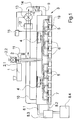
- a device for spinning according to the invention is shown in section. From an extruder 1 via a melt feed line 2, the spinning beam 3 polymer melt fed. Instead of extruder 1, one can also be used here direct polycondensation serve as a source for the polymer melt.
- the melt feed line 2 is divided into two spinning pumps 4 on.
- the spinning pumps 4 distribute the polymer melt in a metered manner via the distributor lines 5 on the individual, housed in the spin pot holders 6 and Spin pots, not shown here. In these spinning pots, the polymer melt becomes the filaments are extruded to form the thread. Both the number the spin pot receptacles 6 and the number of spin pumps 4 are exemplary here selected.
- a cavity 7 is formed, which with a Heat transfer medium is filled.
- This heat transfer medium circulates over one Inlet 8.1 and an outlet 8.2 through an operating heating medium 8.3.
- the operating heating means 8.3 to operating temperature heated, the usual operating temperature being 250 to 330 ° C.
- Oil or diphyl are known as the heat transfer medium.
- Diphyl has the advantage that it is in the liquid and gaseous phase in the spinning beam 3, so that cold components of the spinning beam 3 by condensation of the gaseous Diphyls are specifically heated by the resulting heat of condensation.
- the operating heating of the melt feed line is 2, which interacts with the service heating 8.3 or is operated separately, here not shown.
- the length of the split melt feed line 2 as well as the length of the Distribution lines 5 to the respective spin pot receptacles 6 for each branch is the same and thus the residence time of the melt in the melt-carrying Parts of the spinning beam 3 is the same for each spinning pot holder 6, it can despite the uniform temperature in the spinning beam 3 to degenerate the polymer come.
- a regeneration heater is therefore provided on the spinning beam 3 in FIG. 1, with which the spinning beam 3 to a regeneration temperature above the Operating temperature can be heated.
- the regeneration heater is a hot air blower that comes from the Hot air outlet 10, the filter 12, the blower 13, the regeneration heating medium 14 and the hot air supply 9 there.
- a control means 15 detects the temperature by means of a temperature sensor 19 in the spinning beam 3 and controls the fan 13 and the regeneration heating means 14 based on a setpoint / actual value comparison.
- the spinning pots not shown here removed from the spin pot receptacles 6, so that the openings of the distribution lines 5 are open.
- An opening 2.1 is provided on the melt feed line 2, through which compressed air can be blown into the melt line system.
- the melt feed line 2 is via the opening 2.1 with a suction device 2.2 connected by which arise during the regeneration process Gases are sucked off and filtered.
- the regeneration heater can be permanently connected to the spinning beam. It is but also possible and economically sensible, the filter 12, the blower 13, the Regeneration heating means 14 and the control means 15 can be dismantled, see above that there is a need for the hot air supply 9 and the hot air outlet 10 of the regenerating spinning beam can be attached. This makes it enough for a manufacturer of man-made fibers, only one regeneration heater for several spinning beams reproach.
- the spinning beam according to the invention also comprises other embodiments the operational heating, such as the (electrical) trace heating of the melt-carrying components. These are known from the prior art. The same applies to the following figure.
- FIG. 2 shows a variant of the spinning beam 3 shown in FIG. 1.
- the Regeneration heating means 16 are based here on additional electrical heating of the spinning beam 3. Although here the cavity of the spin beam is not is flowed through by hot air, is still a collection reservoir 8.4 for the Heat transfer medium provided, as a rule, the heat transfer media used are not heat-resistant in the range of the regeneration temperatures. in the Spin beam 3 remaining residues of the heat transfer medium evaporate during of the regeneration process and are sucked off by a suction device 20.
- the spinning beam is well insulated from the outside while the components conduct the heat relatively well inside. Thereby and through the heat radiation inside the spinning beam 3 there is a sufficiently uniform heat distribution reached, the requirements for the regeneration process Temperature uniformity are not as high as in spinning.
- the number and the respective location of the regeneration heating means 16 are derived from the Construction of the spinning beam 3 and can by a specialist accordingly be interpreted.
- the regeneration heating means 16 are as heating coils, Heaters etc. run and transfer the heat through heat conduction or Thermal radiation.
- the regeneration heating means 16 can either be permanently installed in the spinning beam 3 or be designed to be replaceable. Especially in connection with heating elements, it is advisable to use them especially for this provided openings in the normal operation, which are closed by plugs Use spinning beam 3.
- the spinning beam 3 is heated here in normal spinning mode (service heating) not via a heat transfer medium, but through heating means 17 on the individual melt-carrying parts, which are executed here as trace heating are.
- heating means 17 are controlled by a control means 18 which e.g. the Temperature control includes.
- the control means 18 has a separate one Operating mode in which the heating medium with a higher regeneration temperature are operable, so that the regeneration process with the operating heating medium at the same time is feasible.
Landscapes
- Engineering & Computer Science (AREA)
- Mechanical Engineering (AREA)
- Textile Engineering (AREA)
- Spinning Methods And Devices For Manufacturing Artificial Fibers (AREA)
- Materials For Medical Uses (AREA)
- Chemical Or Physical Treatment Of Fibers (AREA)
Abstract
Description
- Fig. 1:
- einen Schnitt durch eine erfindungsgemäße Vorrichtung zum Spinnen,
- Fig. 2:
- einen Schnitt durch eine Ausführungsvariante der erfindungsgemäßen Vorrichtung,
- Fig. 3:
- einen Schnitt durch eine weitere Ausführungsvariante der erfindungsgemäßen Vorrichtung.
- 1.
- Extruder
- 2.
- Schmelzezuleitung
- 2.1
- Öffnung
- 2.2
- Absaugmittel
- 3.
- Spinnbalken
- 4.
- Spinnpumpe
- 5.
- Verteilerleitung
- 6.
- Spinntopfaufnahme
- 7.
- Hohlraum
- 8.1
- Wärmeträgermedium Zulauf
- 8.2
- Wärmeträgermedium Ablauf
- 8.3
- Betriebsheizmittel
- 8.4
- Auffangbehälter
- 9.
- Heißluftzufuhr
- 10.
- Heißluftauslass
- 11.
- Zweiter Heißluftkanal
- 12.
- Filter
- 13.
- Gebläse
- 14.
- Regenerationsheizmittel
- 15.
- Steuermittel
- 16.
- Regenerationsheizmittel
- 17.
- Heizmittel
- 18.
- Steuermittel
- 19.
- Temperaturmessfühler
- 20.
- Absaugmittel
Claims (8)
- Vorrichtung zum Spinnen von schmelzgesponnenen Filamentgarnen,
mit einem Spinnbalken (3),
sowie mit zumindest einer Schmelzezuleitung (2) zum Zuleiten von Polymerschmelze zum Spinnbalken (3),
wobei der Spinnbalken (3)
Verteilerleitungen (5) zur Weiterverteilung der Polymerschmelze, Spinntopfaufnahmen (6) zur Aufnahmen von Spinntöpfen zum Extrudieren der Schmelze zu Filamentgarnen,
und eine Betriebsheizmittel (8.3) zum Beheizen des Spinnbalkens (3) auf eine Betriebstemperatur während des Spinnens enthält,
dadurch gekennzeichnet, dass
der Spinnbalken (3) eine zusätzliche Regenerationsheizeinrichtung (14, 16) enthält, mit der der Spinnbalken (3) auf eine Regenerationstemperatur oberhalb der Betriebstemperatur beheizbar ist. - Vorrichtung nach Anspruch 1,
dadurch gekennzeichnet, dass
die Regenerationsheizung (14, 16) für das Durchführen des Regenerationsvorganges an den Spinnbalken (3) anbaubar ist.. - Vorrichtung nach Anspruch 1 oder 2,
dadurch gekennzeichnet, dass
die Regenerationsheizung (16) eine elektrische Widerstandsheizung ist. - Vorrichtung nach Anspruch 1 oder 2,
dadurch gekennzeichnet, dass
die Regenerationsheizung (14) ein Heißluftgebläse ist. - Vorrichtung nach dem Oberbegriff des Anspruchs 1,
dadurch gekennzeichnet, dass
die Betriebsheizung (17) in einem Regenerationsmodus betreibbar ist, in der der Spinnbalken (3) auf eine Temperatur oberhalb der Betriebstemperatur, vorzugsweise auf 450 bis 550 °C, aufheizbar ist. - Vorrichtung nach einem der vorhergehenden Ansprüche,
dadurch gekennzeichnet, dass
Absaugmittel (2.2) zum Absaugen der während des Regenerationsvorganges in Folge der Regeneration der Schmelzeablagerungen entstehenden Gase und Dämpfe vorhanden sind. - Vorrichtung nach einem der vorhergehenden Ansprüche,
dadurch gekennzeichnet, dass
die Betriebsheizung die Wärme mit einem Wärmeträgermedium überträgt und dass Absaugmittel (20) zum Absaugen der während des Regenerationsvorganges in Folge der Zersetzung des Wärmeträgermediums entstehenden Gase und Dämpfe vorhanden sind. - Vorrichtung nach Anspruch 6 oder 7,
dadurch gekennzeichnet, dass
Mittel zum Filtern (12, 2.2, 20) der abgesaugten Gase und Dämpfe vorhanden sind.
Applications Claiming Priority (2)
| Application Number | Priority Date | Filing Date | Title |
|---|---|---|---|
| DE10258261 | 2002-12-13 | ||
| DE10258261A DE10258261A1 (de) | 2002-12-13 | 2002-12-13 | Spinnbalken |
Publications (2)
| Publication Number | Publication Date |
|---|---|
| EP1431427A1 true EP1431427A1 (de) | 2004-06-23 |
| EP1431427B1 EP1431427B1 (de) | 2006-12-06 |
Family
ID=32336280
Family Applications (1)
| Application Number | Title | Priority Date | Filing Date |
|---|---|---|---|
| EP03022828A Expired - Lifetime EP1431427B1 (de) | 2002-12-13 | 2003-10-08 | Spinnbalken |
Country Status (4)
| Country | Link |
|---|---|
| US (1) | US7172399B2 (de) |
| EP (1) | EP1431427B1 (de) |
| AT (1) | ATE347626T1 (de) |
| DE (2) | DE10258261A1 (de) |
Cited By (1)
| Publication number | Priority date | Publication date | Assignee | Title |
|---|---|---|---|---|
| EP4365339A1 (de) * | 2022-11-02 | 2024-05-08 | Trützschler Group SE | Spinnbalken zur herstellung von schmelzgesponnenen filamenten oder garnen |
Families Citing this family (9)
| Publication number | Priority date | Publication date | Assignee | Title |
|---|---|---|---|---|
| US8512509B2 (en) * | 2007-12-19 | 2013-08-20 | Applied Materials, Inc. | Plasma reactor gas distribution plate with radially distributed path splitting manifold |
| DE112011101081B4 (de) * | 2010-11-16 | 2019-09-05 | Korea Institute Of Industrial Technology | Mehrfachfaser-Spinnvorrichtung und Verfahren zu deren Regelung |
| CN103255587B (zh) * | 2012-09-16 | 2016-08-24 | 仙桃市德兴塑料制品有限公司 | 高过滤性无纺布自动生产系统及其生产的三m复合无纺布 |
| DE102015100179A1 (de) * | 2015-01-08 | 2016-07-14 | TRüTZSCHLER GMBH & CO. KG | Spinnbalken zur Herstellung von schmelzgesponnenen Filamentgarnen |
| FR3037789A1 (fr) * | 2015-06-23 | 2016-12-30 | Rondol Ind | Ligne de production pour la production de medicaments, et installation de production comprenant une telle ligne de production |
| JP6696322B2 (ja) * | 2016-06-24 | 2020-05-20 | 東京エレクトロン株式会社 | ガス処理装置、ガス処理方法及び記憶媒体 |
| CA3056171A1 (en) | 2017-03-17 | 2018-09-20 | Ives BOURGONJON | Polypropylene composition with improved tensile properties, fibers and nonwoven structures |
| KR101887147B1 (ko) | 2018-05-08 | 2018-08-09 | 주식회사 월드로 | 용융 멀티방사 시스템용 히팅장치 |
| CN110528091B (zh) * | 2019-08-23 | 2024-08-09 | 神马实业股份有限公司 | 聚合物熔融纺丝加工装置 |
Citations (3)
| Publication number | Priority date | Publication date | Assignee | Title |
|---|---|---|---|---|
| DE1959180A1 (de) * | 1968-11-26 | 1970-06-18 | Teijin Ltd | Verfahren zur Regelung der Temperatur in einer ummantelten Kammer in einer Schmelzspinnmaschine |
| DE2310463A1 (de) * | 1973-02-20 | 1974-09-19 | Japan Steel Works Ltd | Verfahren zur kontinuierlichen thermischen zersetzung von synthetischen makromolekularen materialien |
| JP2002227026A (ja) * | 2001-01-31 | 2002-08-14 | Teijin Ltd | 溶融紡糸装置 |
Family Cites Families (18)
| Publication number | Priority date | Publication date | Assignee | Title |
|---|---|---|---|---|
| FR1229726A (de) | 1958-01-11 | 1960-09-09 | ||
| IT941066B (it) * | 1971-06-19 | 1973-03-01 | Jenne S R L | Cella modulare per la filatura di fibre sintetiche |
| US3864068A (en) * | 1973-02-09 | 1975-02-04 | Gen Mills Inc | Hot melt extrusion apparatus |
| DE3575313D1 (de) | 1984-05-26 | 1990-02-15 | Barmag Barmer Maschf | Spinnbalken zum schmelzspinnen synthetischer faeden. |
| US4698008A (en) | 1984-06-22 | 1987-10-06 | Barmag Ag | Melt spinning apparatus |
| JP2510672B2 (ja) | 1988-04-21 | 1996-06-26 | 東レ株式会社 | 溶融紡糸装置および該装置による溶融紡糸方法 |
| DE4000218C1 (de) * | 1990-01-05 | 1990-12-06 | Automatik Apparate-Maschinenbau Gmbh, 8754 Grossostheim, De | |
| CH688044A5 (de) | 1993-06-21 | 1997-04-30 | Rieter Automatik Gmbh | Spinnbalken zum Schmelzspinnen endloser Faeden. |
| DE9313586U1 (de) | 1993-09-08 | 1993-11-04 | Synthetik Fiber Machinery, 63762 Großostheim | Spinnbalken |
| IT1276034B1 (it) | 1994-11-10 | 1997-10-24 | Barmag Barmer Maschf | Traversa di filatura per la filatura di una pluralita' di fili sintetici e procedimento per la sua produzione |
| CN1064724C (zh) | 1994-12-02 | 2001-04-18 | 巴马格股份公司 | 带纺多股人造丝的纺丝保温箱体的纺丝设备 |
| DE29517100U1 (de) * | 1995-10-17 | 1997-02-13 | Zimmer, Johannes, Klagenfurt | Strömungsteilungs- und -umformungskörper |
| EP0828017B1 (de) | 1996-09-04 | 2001-11-28 | B a r m a g AG | Spinnbalken |
| CN1107125C (zh) | 1996-12-18 | 2003-04-30 | 巴马格股份公司 | 纺丝箱体 |
| US5866050A (en) * | 1997-02-06 | 1999-02-02 | E. I. Du Pont De Nemours And Company | Method and spinning apparatus having a multiple-temperature control arrangement therein |
| DE19815546C2 (de) | 1998-04-07 | 2000-10-05 | Schiessl Helmut F | Topfspinnvorrichtung |
| DE19905859A1 (de) | 1999-02-12 | 2000-08-17 | Schlafhorst & Co W | Zentrifugenspinnmaschine und Verfahren zum Zentrifugenspinnen |
| DE19920682B4 (de) | 1999-05-05 | 2007-04-12 | Zimmer Ag | Dampfbeschleierung für Spinnsystem mit Rechteckdüsen |
-
2002
- 2002-12-13 DE DE10258261A patent/DE10258261A1/de not_active Withdrawn
-
2003
- 2003-10-08 AT AT03022828T patent/ATE347626T1/de not_active IP Right Cessation
- 2003-10-08 EP EP03022828A patent/EP1431427B1/de not_active Expired - Lifetime
- 2003-10-08 DE DE50305893T patent/DE50305893D1/de not_active Expired - Fee Related
- 2003-12-11 US US10/733,697 patent/US7172399B2/en not_active Expired - Fee Related
Patent Citations (3)
| Publication number | Priority date | Publication date | Assignee | Title |
|---|---|---|---|---|
| DE1959180A1 (de) * | 1968-11-26 | 1970-06-18 | Teijin Ltd | Verfahren zur Regelung der Temperatur in einer ummantelten Kammer in einer Schmelzspinnmaschine |
| DE2310463A1 (de) * | 1973-02-20 | 1974-09-19 | Japan Steel Works Ltd | Verfahren zur kontinuierlichen thermischen zersetzung von synthetischen makromolekularen materialien |
| JP2002227026A (ja) * | 2001-01-31 | 2002-08-14 | Teijin Ltd | 溶融紡糸装置 |
Non-Patent Citations (2)
| Title |
|---|
| PATENT ABSTRACTS OF JAPAN vol. 0140, no. 37 (C - 680) 24 January 1990 (1990-01-24) * |
| PATENT ABSTRACTS OF JAPAN vol. 2002, no. 12 12 December 2002 (2002-12-12) * |
Cited By (1)
| Publication number | Priority date | Publication date | Assignee | Title |
|---|---|---|---|---|
| EP4365339A1 (de) * | 2022-11-02 | 2024-05-08 | Trützschler Group SE | Spinnbalken zur herstellung von schmelzgesponnenen filamenten oder garnen |
Also Published As
| Publication number | Publication date |
|---|---|
| DE10258261A1 (de) | 2004-06-24 |
| US7172399B2 (en) | 2007-02-06 |
| ATE347626T1 (de) | 2006-12-15 |
| DE50305893D1 (de) | 2007-01-18 |
| US20040124551A1 (en) | 2004-07-01 |
| EP1431427B1 (de) | 2006-12-06 |
Similar Documents
| Publication | Publication Date | Title |
|---|---|---|
| DE102011117458A1 (de) | Vorrichtung zum Schmelzspinnen und Abkühlen von synthetischen Filamenten | |
| EP1431427B1 (de) | Spinnbalken | |
| US2253176A (en) | Method and apparatus for production of structures | |
| EP3799584B1 (de) | Vorrichtung und verfahren zur in-situ-schneckenimprägnierung und extrusion von endlosfasern | |
| DE69405560T2 (de) | Reinigung von filtern | |
| WO2013030400A1 (de) | Extrusionsverfahren und -vorrichtung | |
| EP2122019B1 (de) | Vorrichtung zum schmelzspinnen synthetischer filamente | |
| DE10143070A1 (de) | Verfahren und Vorrichtung zum Schmelzspinnen eines multifilen Mehrkomponentenfadens | |
| EP2209604B1 (de) | Verfahren zum extrudieren von kunststoffteilen | |
| DE102013014572A1 (de) | Vorrichtung zum Schmelzspinnen und Abkühlen synthetischer Filamente | |
| DE69520955T2 (de) | Verfahren zum zufasern eines mineralen materials mit einem organischen material | |
| WO2020104434A1 (de) | Verfahren und vorrichtung zum schmelzspinnen von filamenten | |
| AT512520B1 (de) | Filtereinrichtung | |
| DE10340724A1 (de) | Abschreckvorrichtung | |
| EP1190124B1 (de) | Spinnvorrichtung zum verspinnen schmelzflüssiger polymere und verfahren zum beheizen der spinnvorrichtung | |
| WO2001009413A1 (de) | Selbstdichtende kompaktdüse für schmelzspinnverfahren | |
| DE2639282A1 (de) | Beheizbarer verteilerblock zur schmelzverteilung im spinnbalken | |
| EP3678833B1 (de) | Verfahren und vorrichtung zum reinigen einer polymerschmelze | |
| DE102004059069A1 (de) | Vertropfungsanlage | |
| WO2020104256A1 (de) | Spinnbalken | |
| DE102019120827A1 (de) | Galette | |
| DE102013013254A1 (de) | Vorrichtung zum Schmelzspinnen und Abkühlen multifiler Fäden | |
| DE102010013653A1 (de) | Vorrichtung zum Sammeln von Flusen in einem Wäschetrockner, Wäschetrockner und Verfahren zum Entfernen von Flusen von einem Flusensieb | |
| WO2013153018A1 (de) | Vorrichtung zur herstellung synthetischer fäden | |
| DE212004000010U1 (de) | Vorrichtung zum Spinnen von Fäden bildenden Stoffen |
Legal Events
| Date | Code | Title | Description |
|---|---|---|---|
| PUAI | Public reference made under article 153(3) epc to a published international application that has entered the european phase |
Free format text: ORIGINAL CODE: 0009012 |
|
| AK | Designated contracting states |
Kind code of ref document: A1 Designated state(s): AT BE BG CH CY CZ DE DK EE ES FI FR GB GR HU IE IT LI LU MC NL PT RO SE SI SK TR |
|
| AX | Request for extension of the european patent |
Extension state: AL LT LV MK |
|
| 17P | Request for examination filed |
Effective date: 20040730 |
|
| AKX | Designation fees paid |
Designated state(s): AT BE CH DE IT LI TR |
|
| RBV | Designated contracting states (corrected) |
Designated state(s): AT BE CH DE IT LI TR |
|
| GRAP | Despatch of communication of intention to grant a patent |
Free format text: ORIGINAL CODE: EPIDOSNIGR1 |
|
| GRAS | Grant fee paid |
Free format text: ORIGINAL CODE: EPIDOSNIGR3 |
|
| GRAA | (expected) grant |
Free format text: ORIGINAL CODE: 0009210 |
|
| AK | Designated contracting states |
Kind code of ref document: B1 Designated state(s): AT BE CH DE IT LI TR |
|
| REG | Reference to a national code |
Ref country code: CH Ref legal event code: EP |
|
| REF | Corresponds to: |
Ref document number: 50305893 Country of ref document: DE Date of ref document: 20070118 Kind code of ref document: P |
|
| RAP2 | Party data changed (patent owner data changed or rights of a patent transferred) |
Owner name: OERLIKON TEXTILE GMBH & CO. KG |
|
| PLBE | No opposition filed within time limit |
Free format text: ORIGINAL CODE: 0009261 |
|
| STAA | Information on the status of an ep patent application or granted ep patent |
Free format text: STATUS: NO OPPOSITION FILED WITHIN TIME LIMIT |
|
| 26N | No opposition filed |
Effective date: 20070907 |
|
| PGFP | Annual fee paid to national office [announced via postgrant information from national office to epo] |
Ref country code: DE Payment date: 20071030 Year of fee payment: 5 |
|
| PGFP | Annual fee paid to national office [announced via postgrant information from national office to epo] |
Ref country code: CH Payment date: 20071029 Year of fee payment: 5 Ref country code: AT Payment date: 20071024 Year of fee payment: 5 Ref country code: IT Payment date: 20071017 Year of fee payment: 5 |
|
| PGFP | Annual fee paid to national office [announced via postgrant information from national office to epo] |
Ref country code: BE Payment date: 20071029 Year of fee payment: 5 |
|
| PGFP | Annual fee paid to national office [announced via postgrant information from national office to epo] |
Ref country code: TR Payment date: 20071004 Year of fee payment: 5 |
|
| BERE | Be: lapsed |
Owner name: SAURER G.M.B.H. & CO. KG Effective date: 20081031 |
|
| REG | Reference to a national code |
Ref country code: CH Ref legal event code: PL |
|
| PG25 | Lapsed in a contracting state [announced via postgrant information from national office to epo] |
Ref country code: IT Free format text: LAPSE BECAUSE OF NON-PAYMENT OF DUE FEES Effective date: 20081008 Ref country code: DE Free format text: LAPSE BECAUSE OF NON-PAYMENT OF DUE FEES Effective date: 20090501 Ref country code: AT Free format text: LAPSE BECAUSE OF NON-PAYMENT OF DUE FEES Effective date: 20081008 |
|
| PG25 | Lapsed in a contracting state [announced via postgrant information from national office to epo] |
Ref country code: BE Free format text: LAPSE BECAUSE OF NON-PAYMENT OF DUE FEES Effective date: 20081031 |
|
| PG25 | Lapsed in a contracting state [announced via postgrant information from national office to epo] |
Ref country code: LI Free format text: LAPSE BECAUSE OF NON-PAYMENT OF DUE FEES Effective date: 20081031 Ref country code: CH Free format text: LAPSE BECAUSE OF NON-PAYMENT OF DUE FEES Effective date: 20081031 |
|
| PG25 | Lapsed in a contracting state [announced via postgrant information from national office to epo] |
Ref country code: TR Free format text: LAPSE BECAUSE OF NON-PAYMENT OF DUE FEES Effective date: 20100921 |
|
| PG25 | Lapsed in a contracting state [announced via postgrant information from national office to epo] |
Ref country code: TR Free format text: LAPSE BECAUSE OF NON-PAYMENT OF DUE FEES Effective date: 20081008 |