EP1429857B1 - Verfahren zur prozessführung der trennung von mehrstoffgemischen - Google Patents
Verfahren zur prozessführung der trennung von mehrstoffgemischen Download PDFInfo
- Publication number
- EP1429857B1 EP1429857B1 EP02764873A EP02764873A EP1429857B1 EP 1429857 B1 EP1429857 B1 EP 1429857B1 EP 02764873 A EP02764873 A EP 02764873A EP 02764873 A EP02764873 A EP 02764873A EP 1429857 B1 EP1429857 B1 EP 1429857B1
- Authority
- EP
- European Patent Office
- Prior art keywords
- column
- concentration
- process model
- feed
- control
- Prior art date
- Legal status (The legal status is an assumption and is not a legal conclusion. Google has not performed a legal analysis and makes no representation as to the accuracy of the status listed.)
- Expired - Lifetime
Links
- 238000000034 method Methods 0.000 title claims abstract description 63
- 230000008569 process Effects 0.000 title claims abstract description 45
- 239000000203 mixture Substances 0.000 title claims abstract description 18
- 239000000126 substance Substances 0.000 title abstract description 8
- 238000009835 boiling Methods 0.000 claims abstract description 9
- 238000004821 distillation Methods 0.000 claims abstract description 9
- 239000000047 product Substances 0.000 claims description 27
- 238000004458 analytical method Methods 0.000 claims description 19
- 238000004886 process control Methods 0.000 claims description 13
- 239000007788 liquid Substances 0.000 claims description 10
- 238000012856 packing Methods 0.000 claims description 6
- 238000010438 heat treatment Methods 0.000 claims description 5
- 238000005259 measurement Methods 0.000 claims description 4
- 239000007795 chemical reaction product Substances 0.000 claims description 3
- 238000010992 reflux Methods 0.000 claims description 3
- 239000007791 liquid phase Substances 0.000 claims 5
- 230000002035 prolonged effect Effects 0.000 claims 1
- 238000000926 separation method Methods 0.000 abstract description 20
- 239000000470 constituent Substances 0.000 abstract 1
- ZPTVNYMJQHSSEA-UHFFFAOYSA-N 4-nitrotoluene Chemical compound CC1=CC=C([N+]([O-])=O)C=C1 ZPTVNYMJQHSSEA-UHFFFAOYSA-N 0.000 description 12
- 230000008859 change Effects 0.000 description 9
- 239000012467 final product Substances 0.000 description 7
- 239000000463 material Substances 0.000 description 5
- QZYHIOPPLUPUJF-UHFFFAOYSA-N 3-nitrotoluene Chemical compound CC1=CC=CC([N+]([O-])=O)=C1 QZYHIOPPLUPUJF-UHFFFAOYSA-N 0.000 description 4
- 230000035945 sensitivity Effects 0.000 description 4
- YXFVVABEGXRONW-UHFFFAOYSA-N Toluene Chemical compound CC1=CC=CC=C1 YXFVVABEGXRONW-UHFFFAOYSA-N 0.000 description 3
- 238000009834 vaporization Methods 0.000 description 3
- 230000008016 vaporization Effects 0.000 description 3
- PLAZTCDQAHEYBI-UHFFFAOYSA-N 2-nitrotoluene Chemical compound CC1=CC=CC=C1[N+]([O-])=O PLAZTCDQAHEYBI-UHFFFAOYSA-N 0.000 description 2
- 230000008901 benefit Effects 0.000 description 2
- 238000009833 condensation Methods 0.000 description 2
- 230000005494 condensation Effects 0.000 description 2
- 238000011109 contamination Methods 0.000 description 2
- VLZLOWPYUQHHCG-UHFFFAOYSA-N nitromethylbenzene Chemical class [O-][N+](=O)CC1=CC=CC=C1 VLZLOWPYUQHHCG-UHFFFAOYSA-N 0.000 description 2
- 230000000630 rising effect Effects 0.000 description 2
- 230000006978 adaptation Effects 0.000 description 1
- 238000009530 blood pressure measurement Methods 0.000 description 1
- 238000009529 body temperature measurement Methods 0.000 description 1
- 238000006243 chemical reaction Methods 0.000 description 1
- 230000008878 coupling Effects 0.000 description 1
- 238000010168 coupling process Methods 0.000 description 1
- 238000005859 coupling reaction Methods 0.000 description 1
- 238000001514 detection method Methods 0.000 description 1
- 238000010586 diagram Methods 0.000 description 1
- VMMLSJNPNVTYMN-UHFFFAOYSA-N dinitromethylbenzene Chemical class [O-][N+](=O)C([N+]([O-])=O)C1=CC=CC=C1 VMMLSJNPNVTYMN-UHFFFAOYSA-N 0.000 description 1
- 238000002845 discoloration Methods 0.000 description 1
- 238000005516 engineering process Methods 0.000 description 1
- 238000001704 evaporation Methods 0.000 description 1
- 230000008020 evaporation Effects 0.000 description 1
- 239000012530 fluid Substances 0.000 description 1
- 210000003918 fraction a Anatomy 0.000 description 1
- 239000000446 fuel Substances 0.000 description 1
- 239000012535 impurity Substances 0.000 description 1
- 230000010354 integration Effects 0.000 description 1
- 238000011835 investigation Methods 0.000 description 1
- 238000012423 maintenance Methods 0.000 description 1
- SYSQUGFVNFXIIT-UHFFFAOYSA-N n-[4-(1,3-benzoxazol-2-yl)phenyl]-4-nitrobenzenesulfonamide Chemical class C1=CC([N+](=O)[O-])=CC=C1S(=O)(=O)NC1=CC=C(C=2OC3=CC=CC=C3N=2)C=C1 SYSQUGFVNFXIIT-UHFFFAOYSA-N 0.000 description 1
- 238000006396 nitration reaction Methods 0.000 description 1
- 238000010986 on-line near-infrared spectroscopy Methods 0.000 description 1
- 230000009467 reduction Effects 0.000 description 1
- 230000001105 regulatory effect Effects 0.000 description 1
- 238000005070 sampling Methods 0.000 description 1
- 239000002689 soil Substances 0.000 description 1
- 238000004611 spectroscopical analysis Methods 0.000 description 1
- 238000012546 transfer Methods 0.000 description 1
- 230000007704 transition Effects 0.000 description 1
Images

Classifications
-
- B—PERFORMING OPERATIONS; TRANSPORTING
- B01—PHYSICAL OR CHEMICAL PROCESSES OR APPARATUS IN GENERAL
- B01D—SEPARATION
- B01D3/00—Distillation or related exchange processes in which liquids are contacted with gaseous media, e.g. stripping
- B01D3/42—Regulation; Control
- B01D3/4211—Regulation; Control of columns
- B01D3/4255—Head-, side-, bottom- and feed stream
-
- B—PERFORMING OPERATIONS; TRANSPORTING
- B01—PHYSICAL OR CHEMICAL PROCESSES OR APPARATUS IN GENERAL
- B01D—SEPARATION
- B01D3/00—Distillation or related exchange processes in which liquids are contacted with gaseous media, e.g. stripping
- B01D3/14—Fractional distillation or use of a fractionation or rectification column
- B01D3/143—Fractional distillation or use of a fractionation or rectification column by two or more of a fractionation, separation or rectification step
- B01D3/146—Multiple effect distillation
-
- G—PHYSICS
- G05—CONTROLLING; REGULATING
- G05B—CONTROL OR REGULATING SYSTEMS IN GENERAL; FUNCTIONAL ELEMENTS OF SUCH SYSTEMS; MONITORING OR TESTING ARRANGEMENTS FOR SUCH SYSTEMS OR ELEMENTS
- G05B17/00—Systems involving the use of models or simulators of said systems
- G05B17/02—Systems involving the use of models or simulators of said systems electric
-
- Y—GENERAL TAGGING OF NEW TECHNOLOGICAL DEVELOPMENTS; GENERAL TAGGING OF CROSS-SECTIONAL TECHNOLOGIES SPANNING OVER SEVERAL SECTIONS OF THE IPC; TECHNICAL SUBJECTS COVERED BY FORMER USPC CROSS-REFERENCE ART COLLECTIONS [XRACs] AND DIGESTS
- Y10—TECHNICAL SUBJECTS COVERED BY FORMER USPC
- Y10T—TECHNICAL SUBJECTS COVERED BY FORMER US CLASSIFICATION
- Y10T436/00—Chemistry: analytical and immunological testing
- Y10T436/25—Chemistry: analytical and immunological testing including sample preparation
Definitions
- the invention relates to a process for carrying out the separation of multicomponent mixtures of known composition in distillation columns.
- the invention relates to the separation of multicomponent mixtures with closely spaced boiling points, e.g. Isomer mixtures which are separated into their isomeric substance components with high product purity.
- the NIR analysis When measuring the concentration of the final product (p-nitrotoluene), the NIR analysis provides measured values which, due to the high concentration of p-nitrotoluene, do not have the required accuracy.
- the invention is based on the idea to attach the analyzer in the product stream between the two columns. If you then connect the analyzer in a control loop, so you can keep constant the concentration in the product flow between the two column sections. However, this does not ensure that the concentration of the final product drawn off at the bottom of the second column section remains constant. The reason for this is that the separation performance of the second column part, that between the point of attachment device and the bottom of the column, is subject to constant changes due to regulatory interventions and disturbances.
- the object of the invention is achieved in that the online analyzer is coupled in the arrangement described above with an online process model.
- the process can also be used for a column divided into at least two partial columns, the concentration measurement a) taking place in the region between the partial columns.
- a variant of the method with partial columns characterized in that instead of the temperatures and flow rates of inlet and return and the heating energy in particular the amount of steam and the flow rates between the two sub-columns and their temperatures are used in the process model.
- the analyzer is preferably arranged in the region between the uppermost fifth and the lowest fifth of the length of the overall column.
- the measured value of the liquid flow between the two partial columns can be used together with the heating energy in the process model.
- other analyzers can also be used, eg gas chromatographs, UV-VIS spectrometers, liquid chromatographs.
- the concentration is determined at a given temperature sensitivity preferably via a temperature and pressure measurement.
- the combination of online analysis and process model can also be used to control the concentration of the overhead product.
- the process is used in particular for the isomer separation of nitrotoluene and is preferably stirred as follows.
- the analyzer measures the concentration of one component (e.g., p-nitrotoluene) in the product stream between the two column parts and passes that information to the process model. Based on this information, the model calculates, using quantities measured directly at the column, e.g. Flow rates, steam supply and temperatures the p-nitrotoluene concentration in the bottom product.
- the value determined by the model is treated as the actual value of the controlled variable.
- the difference between the setpoint and the actual value is input to the controller, in particular to a PID controller module of the process control system. In case of deviations between setpoint and actual value, the controller changes the manipulated variable, i. the steam supply.
- the value for the sump concentration calculated by the online process model has a predictive character. Faults initiated, for example, by a change in mass flow or concentration in the inlet, are at the location of the device connection captured between the two columns before they reach the swamp.
- the model uses the currently measured concentration value and calculates the resulting new concentration value for the bottoms product based on the currently available separation performance. This value is the concentration that would occur in the bottoms product after about 20 to 30 minutes, if not intervened. Due to the direct coupling of model and controller, the controller changes the steam supply before the concentration failure reaches the sump.
- the process model uses the liquid / vapor ratio as well as the theoretical number of stages of the second column part, which depends on column internals such as trays or packing, to calculate the sump concentration. Since the theoretical number of stages may change due to contamination, for example, the output signal of the process model must be checked at intervals of eg 24 hours on the basis of analysis data. If the model and analysis values deviate, the model parameters are changed automatically. In the present case, the model parameter to be adjusted is the theoretical number of separation stages. This is a physically interpretable size. Their value and change indicates the status of the column internals and can be used, for example, as information for specifying maintenance intervals.
- the numerics of the process model allow its integration into closed-loop control systems. In the control-technically necessary interval times of up to 0.5 s, the model calculates the new concentration values.
- the advantage of the process model lies in the fact that its algorithm is robust and does not contain an iteration method, as eg in US-A-5,260,865 the case is. Compared to the method described in this document, which builds up on the concentration measured in the feed, the present process model assumes concentration measurements at the points of the column where the sensitivity is highest.
- the present process management also has the advantage that the plant operator explicitly sets the desired concentration in the final product as the setpoint of the controlled variable.
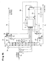
- FIG. 1a a process scheme for an isomer separation is shown.
- a mixture with 70% of the isomer A (p-nitrotoluene) is separated into a top product with 30% and a bottom product with 99.70% isomer A.
- the inlet is located in the lower third of the column part 10.
- the sensor 1 detects the temperature and sensor. 2 the feed quantity of the mixture A, B.
- the low-boiling fraction A, B is condensed via the line 21 to a condenser 16 and partially removed via the line 13.
- the other part is returned as return 22 via a valve with flow regulator 12 and temperature measuring device 11 to the head part 30.
- a measuring point 29 with a near-infrared spectrometer 3 is arranged in the region of the connecting lines.
- a sump removal line 14 is attached, from which a portion of the bottom product via the evaporator 17 and the line 20 is returned to the column part 9.
- the evaporator 17 is acted upon via the control valve 19 from the steam line 18 with steam.
- the measured values of the sensors 1, 2, 24, 11, 12, 18 and the analyzer 3 are fed to the computer 6.
- the sample of the bottom product at certain intervals is analyzed for their composition and with the calculated value of the sump concentration (comparator 8 of the process control system 28, which includes the computer 6).
- the online process model 6 used here, for the binary substance system A, B, has been derived from the stationary laws of thermodynamics and hydrodynamics and has been simplified so that on the one hand this reproduces the process behavior in the intended working range in the accuracy required for the process control and on the other hand runs through a simplified numerics in the process control system 28 and can deliver the required results for the control within the specified interval time.
- the result of the online process model has a predictive character.
- the model in the stripping section 9 reflects its expected rise in the bottoms product with a lead time of approximately 20 minutes.
- the concentration of component A of the product stream leaving the sump corresponds to the sump concentration X A, see below. This results from the concentration of the component A at the measuring point 29 ⁇ A, online analysis and the separation performance between this measuring point and the column bottom 23, measured with the online analyzer.
- the model includes, inter alia, the liquid-to-vapor Ratio a and the theoretical number of separation stages between measuring point 29 and column bottom 23 n available.
- the liquid to vapor ratio a is to be calculated from the feed quantity 2 in combination with the temperature difference determined from the temperatures 1 and 27, the return amount 12 in combination with the temperature difference determined from the temperatures 11 and 24 and the amount of steam18.
- samples 5 are drawn to determine the concentration in product stream 14 that corresponds to the bottoms concentration.
- the concentration is compared 8 with the calculated concentration 25 from the process model.
- the number of separation stages of the process model is adjusted (model adaptation 4).
- the model combines the increased low boiler fraction (low boilers here is component B) at the measuring point with the currently existing separation efficiency, which was sufficient before the disturbance to maintain the sump concentration, a higher low boiler fraction is calculated in the sump concentration, which is not yet available and would be reached only in the equilibrium state, ie after about 20 minutes.
- the value determined by the model 25 is fed to the controller as the actual value of the controlled variable.
- the regulator 7 immediately increases the amount of steam 18 until the increased low-boiler fraction at the measuring point 29, together with the lowered liquid-to-vapor ratio, again leads to the setpoint value 26 of the sump concentration. Since the change in the amount of steam 18 is returned via the model without delay to the controller 7, resulting in a robust control. This is supported by the fact that the controller 7 intervenes before the fault has reached the sump 23 and that due to the early intervention, the manipulated variable changes 19 can be dosed.
Landscapes
- Chemical & Material Sciences (AREA)
- Chemical Kinetics & Catalysis (AREA)
- Physics & Mathematics (AREA)
- General Physics & Mathematics (AREA)
- Engineering & Computer Science (AREA)
- Automation & Control Theory (AREA)
- Vaporization, Distillation, Condensation, Sublimation, And Cold Traps (AREA)
- Investigating Or Analysing Materials By Optical Means (AREA)
- Organic Low-Molecular-Weight Compounds And Preparation Thereof (AREA)
Abstract
Description
- Die Erfindung betrifft ein Verfahren zur Prozessführung der Trennung von Mehrstoffgemischen bekannter Zusammensetzung in Destillationskolonnen. Im Besonderen betrifft die Erfindung die Trennung von Mehrstoffgemischen mit eng beieinander liegenden Siedepunkten, z.B. Isomerengemische, die in ihre isomeren Stoffkomponenten mit hoher Produktreinheit aufgetrennt werden.
- Bei der Nitrierung von Toluol erhält man aus der Reaktionsstufe ein Isomerengemisch bestehend aus ortho-, meta- und para-Nitrotoluol sowie Di-Nitrotoluol-Isomere und weiteren Stoffkomponenten. Die technische Aufgabe besteht darin, die Isomeren o-, m- und p-Nitrotoluol aus diesem Stoffgemisch abzutrennen und in hoher Reinheit von mindestens 99,70 % zu gewinnen. Dies geschieht in einer Reihe hintereinander geschalteter Destillationskolonnen, die zum Teil auch über Kreislaufströme miteinander verbunden sind. Infolge der geringen Siedepunktsdifferenzen der zu gewinnenden Nitrotoluol-Isomeren sind zur Trennung Destillationskolonnen mit einer hohen Trennstufenzahl und hohem Rücklaufverhältnis erforderlich. Im Besonderen erfordert die Trennung von m-, und p-Nitrotoluol, deren Siedepunktdifferenz nur etwa 3 K beträgt, eine hohe Trennstufenzahl. Aus diesem Grund erfolgt die Trennung dieser Isomeren in einer Kolonne, die apparativ in zwei nebeneinanderstehende Kolonnenteile mit insgesamt einem Verdampfer und einem Kondensator aufgeteilt ist. Aufgrund der geringen Temperatursensitivität ist es nicht möglich, die Konzentration von p-Nitrotoluol, das am Sumpf des zweiten Kolonnenteils anfällt, über eine Kolonnentemperatur als Hilfsregelgröße zu regeln.
- Da Kolonnentemperaturen als Hilfsregelgrößen zur Einhaltung der Produktspezifikation von p-Nitrotoluol nicht verwendet werden können, bietet sich der Einsatz von Online-Nahinfrarot-Spektroskopie-Geräten zur Prozessführung an. Allerdings zeigt sich, dass deren Einsatz zur Analyse des Endproduktes, d.h. am Sumpfausgang oder Kolonne zwei wesentliche Nachteile hat. Dies sind:
- Bei der Messung der Konzentration des Endproduktes (p-Nitrotoluol) liefert die NIR-Analyse Messwerte, die aufgrund der hohen Konzentration von p-Nitrotoluol nicht die erforderliche Genauigkeit aufweisen.
- Selbst wenn es gelänge, mit der Analyse die für die Prozessführung erforderliche Genauigkeit zu erzielen, so ist die Anbringung des Messgeräts im Endproduktstrom nicht sinnvoll, da dort Konzentrationsabweichungen zu spät erfasst werden und damit zu spät entgegen gesteuert wird.
- Im Endproduktstrom ist auf Grund der Produkteigenschaft während der Anfahrprozesse des Verfahrens mit erheblichen Verunreinigungen und Verfärbungen zu rechnen. Damit ist die Anwendung der Spektroskopie als Messverfahren für die Regelung des Prozesses ausgeschlossen.
- Eigene Untersuchungen haben gezeigt, dass im Produktstrom zwischen den beiden Kolonnenteilen die höchste Sensitivität bei Konzentrationsänderungen des Sumpfproduktes vorliegt. In dem genannten Produktstrom ist die Konzentrationsänderung um den Faktor 10 höher als die sich daraus ergebende Konzentrationsänderung im Sumpfprodukt. Darüber hinaus liegt in dem Produktstrom zwischen den Kolonnen eine gegenüber dem Endprodukt niedrigere p-Nitrotoluol-Konzentration vor. In diesem Produktstrom wird mit dem Analysengerät daher eine höhere Genauigkeit erzielt. Sie ist etwa doppelt so hoch wie bei einer Messung im Endprodukt.
- Der Erfindung liegt die Idee zugrunde, das Analysengerät in den Produktstrom zwischen den beiden Kolonnen anzubringen. Bindet man das Analysengerät dann in einen Regelkreis ein, so kann man damit die Konzentration in dem Produktstrom zwischen den beiden Kolonnenteilen konstant halten. Es ist damit jedoch nicht gewährleistet, dass auch die Konzentration des am Sumpf des zweiten Kolonnenteils abgezogenen Endprodukts konstant bleibt. Der Grund dafür liegt darin, dass die Trennleistung des zweiten Kolonnenteils, das zwischen der Stelle der Geräteanbringung und dem Kolonnensumpf liegt, aufgrund von Stelleingriffen und Störeinflüssen ständigen Änderungen unterliegt.
- Die Aufgabe der Erfindung wird erfindungsgemäß dadurch gelöst, dass das Online-Analysengerät bei der oben beschriebenen Anordnung mit einem Online-Prozessmodell gekoppelt wird.
- Gegenstand der Erfindung ist ein Verfahren zur Prozessführung von Destillationskolonnen mit einem unteren Kolonnenteil und einem oberen Kolonnenteil unter Regelung der Sumpfkonzentration, wobei mehrere Komponenten A, B vorzugsweise mit eng beieinander liegenden Siedepunkten von einander getrennt werden und wobei die am Sumpf des unteren Kolonnenteils anfallende Stoffkomponente mit hoher Reinheit gewonnen wird, dadurch gekennzeichnet,
- a) dass die Konzentration der Komponenten A, B an einer Stelle der Kolonne außerhalb des Sumpf- oder Kopfbereiches der Kolonne insbesondere an einer Stelle die im mittleren Bereich zwischen dem obersten Zehntel und dem untersten Zehntel der Länge der Gesamtkolonne angeordnet ist mit einem Analysengerät, insbesondere einem Nahinfrarot-Spektrometer online gemessen wird,
- b) dass die nach a) gemessene Konzentration mindestens einer der Komponenten A oder B von einem Online-Prozessmodell in einer Rechnereinheit eines Prozessleitsystems übernommen und benutzt wird, und dass das Prozessmodell unter Verwendung des Messwertes und weiteren direkt an der Kolonne gemessenen Größen ausgewählt aus Temperatur, Druck und Stoff-Mengenströme, insbesondere von Zulauf, Heizmittelzufuhr, insbesondere Dampfzufuhr und Rücklauf, eine Sumpfkonzentration XAsu berechnet innerhalb einer durch das Prozessleitsystem und die Regelungstechnik bedingten Intervallzeit,
- c) dass die unter Verwendung des Prozessmodells berechnete Sumpfkonzentration XAsu zur Regelung verwendet wird, indem die vom Modell berechnete Sumpfkonzentration XAsu regelungstechnisch wie der Istwert der Regelgröße der Sumpfkonzentration behandelt wird,
- d) dass bestimmte Parameter des Prozessmodells physikalisch interpretierbare Größen, insbesondere die theoretische Stufenzahl bezogen auf Packungen oder Füllkörper und/oder den Bodenwirkungsgrad darstellen, die in größeren Zeitintervallen insbesondere von mehreren Stunden, gegebenenfalls auch mehreren Tagen dem jeweiligen Kolonnenzustand, z.B. dem Verschmutzungsgrad, angepasst werden auf der Basis von Analysen des Endproduktes und Eingabe der Analysendaten in das Prozessmodell.
- In einer bevorzugten Variante kann das Verfahren auch für eine in mindestens zwei Teilkolonnen geteilte Kolonne angewendet werden, wobei die Konzentrationsmessung a) im Bereich zwischen den Teilkolonnen erfolgt.
- Bevorzugt ist eine Variante des Verfahrens mit Teilkolonnen, dadurch gekennzeichnet, dass anstelle der Temperaturen und Mengenströme von Zulauf und Rücklauf sowie der Heizenergie insbesondere der Dampfmenge auch die Mengenströme zwischen den beiden Teilkolonnen sowie deren Temperaturen im Prozessmodell verwendet werden.
- Bevorzugt ist in dem Verfahren das Analysengerät im Bereich zwischen dem obersten Fünftel und dem untersten Fünftel der Länge der Gesamtkolonne angeordnet.
- Alternativ kann der Messwert des Flüssigkeitsstromes zwischen den beiden Teilkolonnen zusammen mit der Heizenergie im Prozessmodell verwendet werden. Anstelle eines NIR-Spektrometers können auch andere Analysengeräte eingesetzt werden, z.B. Gaschromatographen, UV-VIS-Spektrometer, Flüssigkeitschromatographen.
- In den Verfahren werden bevorzugt Stoffgemische mit höchstens 20 K insbesondere 10 K auseinander liegenden Siedepunkten getrennt.
- Die Konzentration wird bei gegebener Temperatursensitivität bevorzugt über eine Temperatur- und Druckmessung ermittelt.
- In einer alternativen Variante des Verfahrens kann die Kombination von Online-Analytik und Prozessmodell auch zur Konzentrationsregelung des Kopfproduktes verwendet werden.
- Das Verfahren wird insbesondere für die Isomerentrennung von Nitrotoluol verwendet und bevorzugt wie folgt durchgerührt.
- Das Analysengerät misst die Konzentration von einer Komponente (z.B. p-Nitrotoluol) im Produktstrom zwischen den beiden Kolonnenteilen und gibt diese Information an das Prozessmodell weiter. Aufbauend auf dieser Information berechnet das Modell unter Nutzung von direkt an der Kolonne gemessenen Größen z.B. Mengenströmen, Dampfzufuhr und Temperaturen die p-Nitrotoluol-Konzentration im Sumpfprodukt. Der vom Modell ermittelte Wert wird als Istwert der Regelgröße behandelt. Die Differenz zwischen Soll- und Istwert ist Eingangsgröße in den Regler, insbesondere in einen PID-Regler-Baustein des Prozessleitsystems. Bei Abweichungen zwischen Soll- und Istwert ändert der Regler die Stellgröße, d.h. die Dampfzufuhr.
- Der vom Online-Prozessmodell berechnete Wert für die Sumpfkonzentration hat prädiktiven Charakter. Störungen, eingeleitet z.B. durch eine Änderung von Mengenstrom oder Konzentration im Zulauf, werden an der Stelle des Geräteanschlusses zwischen den beiden Kolonnen erfasst, bevor sie den Sumpf erreichen. Das Modell benutzt den aktuell gemessenen Konzentrationswert und berechnet anhand der gerade vorliegenden Trennleistung den sich daraus ergebenden neuen Konzentrationswert für das Sumpfprodukt. Dieser Wert ist die Konzentration, die sich nach ca. 20 bis 30 Minuten im Sumpfprodukt einstellen würde, wenn nicht eingegriffen werden würde. Aufgrund der direkten Kopplung von Modell und Regler ändert der Regler die Dampfzufuhr, bevor die Konzentrationsstörung den Sumpf erreicht. Durch die Rückkopplung der Dampfmengenänderung über das Modell zum Regler erfolgt die Änderung der Dampfmenge nur soweit, dass sie die Konzentrationsänderung im Produktstrom zwischen den Kolonnenteilen mit einer geänderten Trennleistung des zweiten Kolonnenteils ausgleicht. Das Konzept verwirklicht damit gleichzeitig eine inhärente Stellgrößenbeschränkung. Durch das frühzeitige Erkennen der Störung sowie den rechtzeitigen und dosierten Reglereingriff wird die Arbeitsweise der Prozessführung genau und robust. In
Fig. 1a und1b ist erkennbar, dass die Messwerte der Zulaufmenge und der Zulauftemperatur, sowie die Rücklaufmenge, die Rücklauf- und die Kopftemperatur in das Prozessmodell eingehen und damit auch eine Feedforward-Strategie verwirklicht wird. - Das Prozessmodell benutzt zur Berechnung der Sumpfkonzentration das Flüssigkeits/- Dampfverhältnis sowie die theoretische Stufenzahl des zweiten Kolonnenteils, die von den Kolonneneinbauten wie z.B. Böden oder Packung abhängt. Da sich die theoretische Stufenzahl z.B. durch Verschmutzung ändern kann, muss das Ausgangssignal des Prozessmodells in bestimmten Zeitabständen von z.B. je 24 Stunden anhand von Analysendaten überprüft werden. Bei Abweichungen zwischen Modell- und Analysenwert werden die Modellparameter automatisch geändert. Im vorliegenden Fall ist der anzupassende Modellparameter die theoretische Trennstufenzahl. Dies ist eine physikalisch interpretierbare Größe. Deren Wert und Änderung zeigt den Zustand der Kolonneneinbauten an und kann z.B. als Information zur Festlegung von Instandhaltungsintervallen genutzt werden.
- Die Numerik des Prozessmodells erlaubt dessen Einbindung in geschlossene Regelkreise. In den regelungstechnisch notwendigen Intervallzeiten bis zu 0,5 s berechnet das Modell die neuen Konzentrationswerte. Der Vorteil des Prozessmodells liegt darin, dass dessen Algorithmus robust ist und kein Iterationsverfahren enthält, wie dies z.B. in
US-A-5,260,865 der Fall ist. Im Vergleich zu dem in dieser Druckschrift beschriebenen Verfahren, das auf der im Zulauf gemessenen Konzentration aufbaut, geht das vorliegende Prozessmodell von Konzentrationsmessungen an den Stellen der Kolonne aus, wo die Sensitivität am höchsten ist. - Gegenüber anderen Prozessführungskonzepten, in denen die Sollwerte von Hilfsregelgrößen wie z.B. Temperaturen eingestellt werden, hat die vorliegende Prozessführung auch den Vorteil, dass der Anlagenfahrer die gewünschte Konzentration im Endprodukt als Sollwert der Regelgröße explizit vorgibt.
- Die Erfindung wird nachfolgend anhand der
Figuren 1a und1b durch die Beispiele, welche jedoch keine Beschränkung der Erfindung darstellen, näher erläutert. - Fig. 1a
- zeigt das Verfahrensschema einer Destillationsanlage mit zwei Teilkolonnen
- Fig. 1b
- zeigt das Verfahrensschema einer Destillationsanlage mit einer Kolonne
- In der
Figur 1a ist ein Verfahrensschema für eine Isomerentrennung dargestellt. Ein Gemisch mit 70 %-Anteil des Isomers A (p-Nitrotoluol) wird in ein Kopfprodukt mit 30 % und ein Sumpfprodukt mit 99,70 % Isomeranteil A aufgetrennt. - Über eine Zuleitung 15 wird das Stoffgemisch (p-Nitrotoluol A, m-Nitrotoluol B) dem oberen Kolonnenteil 10 einer zweiteiligen Destillationskolonne 9, 10 zugeführt, der Einlass befindet sich im unteren Drittel des Kolonnenteils 10. Der Sensor 1 erfasst die Temperatur und Sensor 2 die Zulaufmenge des Gemisches A, B.
- Am Kopf 30 der Kolonne 10 mit Temperaturfühler 24 wird die Leichtsiederfraktion A, B über die Leitung 21 an einen Kondensator 16 kondensiert und zum Teil über die Leitung 13 entnommen. Der andere Teil wird als Rücklauf 22 über ein Ventil mit Mengenregler 12 und Temperaturmessgerät 11 zum Kopfteil 30 zurückgeführt.
- Zwischen dem oberen Kolonnenteil 10 und unterem Kolonnenteil 9 ist im Bereich der Verbindungsleitungen eine Messstelle 29 mit einem Nahinfrarot-Spektrometer 3 angeordnet.
- Am Sumpf 23 des unteren Kolonnenteiles 9 ist eine Sumpfentnahmeleitung 14 angebracht, von der ein Teil des Sumpfproduktes über den Verdampfer 17 und die Leitung 20 zum Kolonnenteil 9 zurückgeführt wird. Der Verdampfer 17 wird über das Regelventil 19 aus der Dampfleitung 18 mit Dampf beaufschlagt.
- Die Messwerte der Sensoren 1, 2, 24, 11, 12, 18 und des Analysengerätes 3 werden dem Rechner 6 zugeleitet.
- An der Entnahmestelle 5 wird die Probe des Sumpfproduktes in bestimmten Zeitabständen (z.B. einmal täglich) auf ihre Zusammensetzung analysiert und mit dem berechneten Wert der Sumpfkonzentration verglichen (Vergleicher 8 des Prozessleitsystems 28, das den Rechner 6 umfasst).
- Das hier eingesetzte Online-Prozessmodell 6, für das binäre Stoffsystem A, B, ist aus den stationären Gesetzmäßigkeiten der Thermo- und Hydrodynamik hergeleitet und so vereinfacht worden, dass dies einerseits das Prozessverhalten im vorgesehenen Arbeitsbereich in der für die Prozessführung notwendigen Genauigkeit wiedergibt und andererseits durch eine vereinfachte Numerik im Prozessleitsystem 28 abläuft und die für die Regelung erforderlichen Ergebnisse innerhalb der vorgegebenen Intervallzeit liefern kann.
- Das Ergebnis des Online-Prozessmodells hat prädiktiven Charakter. So gibt das Modell im Abtriebsteil 9 bei einer Störung z.B. einem Anstieg der Leichtsiederkonzentration im Zulauf dessen zu erwartenden Anstieg im Sumpfprodukt mit einer Vorlaufzeit von ca. 20 Minuten wieder. Das Modell berechnet die Sumpfkonzentration der Komponente A aus der vom Analysengerät 3 an der Messstelle 29 gemessenen Konzentration von A gemäß:

- Die Konzentration der Komponente A des aus dem Sumpf austretenden Produktstroms entspricht der Sumpfkonzentration X A, su . Diese ergibt sich aus der mit dem Online-Analysengerät gemessenen Konzentration der Komponente A an der Messstelle 29 X A, online-Analyse und der Trennleistung zwischen dieser Messstelle und dem Kolonnensumpf 23. Zur Berechnung der Trennleistung stehen dem Modell u.a. das Flüssigkeits- zu Dampf -Verhältnis a sowie die theoretische Trennstufenzahl zwischen Messstelle 29 und Kolonnensumpf 23 n zur Verfügung.
- Hierzu werden noch die folgenden Gleichungen 2 bis 6 verwendet:


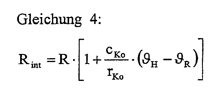


- Das Flüssigkeits- zu Dampf-Verhältnis a ist zu berechnen aus der Zulaufmenge 2 in Kombination mit der Temperaturdifferenz ermittelt aus den Temperaturen 1 und 27, der Rücklaufmenge 12 in Kombination mit der Temperaturdifferenz ermittelt aus den Temperaturen 11 und 24 und der Dampfmenge18.
- Die Trennstufenzahl n ist abhängig von der den Stoffaustausch bestimmenden Hydrodynamik sowie vom Zustand der Packung und des Flüssigkeitsverteilers. Die Trennstufenzahl wird angepasst mittels Laboranalysen unter Verwendung von

- In größeren Zeitabständen werden Proben 5 gezogen, um die Konzentration im Produktstrom 14 zu bestimmen, die der Sumpfkonzentration entspricht. Die Konzentration wird verglichen 8 mit der berechneten Konzentration 25 aus dem Prozessmodell. Bei Abweichungen zwischen gemessener und berechneter Konzentration wird die Trennstufenzahl des Prozessmodells angepasst (Modellanpassung 4).
- Da das Modell den erhöhten Leichtsiederanteil (Leichtsieder ist hier die Komponente B) an der Messstelle mit der gerade vorhandenen Trennleistung, die vor der Störung zur Einhaltung der Sumpfkonzentration ausreichte, verbindet, wird ein höherer Leichtsiederanteil in der Sumpfkonzentration errechnet, der noch nicht vorhanden ist und erst im Gleichgewichtszustand erreicht werden würde, d.h. nach ca. 20 Minuten. Der vom Modell ermittelte Wert 25 wird dem Regler als Istwert der Regelgröße zugeführt. Der Regler 7 erhöht sofort die Dampfmenge 18 soweit, bis der erhöhte Leichtsiederanteil an der Messstelle 29 zusammen mit dem erniedrigten Flüssigkeitszu Dampf-Verhältnis wieder zum Sollwert 26 der Sumpfkonzentration führt. Da die Änderung der Dampfmenge 18 über das Modell ohne Zeitverzug zum Regler 7 zurückgeführt wird, ergibt sich eine robuste Regelung. Dies wird unterstützt durch die Tatsache, dass der Regler 7 eingreift, bevor die Störung den Sumpf 23 erreicht hat und dass infolge des frühzeitigen Eingreifens die Stellgrößenänderungen 19 dosiert erfolgen können.
- Im Falle einer Verringerung des Leichtsiederanteils an der Messstelle 29 wird die Dampfmenge nur soweit zurückgefahren bis der erniedrigte Leichtsiederanteil zusammen mit dem erhöhten Flüssigkeits- zu Dampf-Verhältnis zum Sollwert der Sumpfkonzentration führt. Mit der direkten Rückführung der Dampfmenge 18 über das Modell zurück zum Regler 7 wird die Dampfmenge 18 nur soweit reduziert, wie dies mit dem erniedrigten Leichtsiederanteil an der Messstelle 29 verträglich ist. Dies kann als eine inhärente Stellgrößenbeschränkung betrachtet werden. Die Praxis hat gezeigt, dass sich das System selbst bei starken Störungen robust verhält bei nur geringen Abweichungen des Istwertes vom Sollwert in der Übergangsphase.
- Nachfolgend ist eine Liste der in den Gleichungen benutzten Symbole aufgeführt:
- ϑH
- Temperatur am Kopf der Kolonne
- ϑR
- Temperatur der Rücklaufmenge
- ϑFeed
- Temperatur des Zulaufs
- ϑKol, Fe
- Temperatur der Kolonne an der Zulaufstelle
- cFeed
- Spezifische Wärme des Stoffsystems im Zulauf
- cKo
- Spezifische Wärme des Stoffsystems am Kopf der Kolonne
- rFeed
- Verdampfungswärme des Stoffsystems im Zulauf
- rKo
- Verdampfungswärme des Stoffsystems am Kopf der Kolonne
- rSu
- Verdampfungswärme des Stoffsystems im Sumpf der Kolonne
- rD
- Verdampfungswärme des der Kolonne zugeführten Heizdampfes
- m
- Steigung der Tangente an die Gleichgewichtskurve des für das Stoffsystem und den Druck maßgebenden McCabe-Thiele-Diagramms am unteren linken Punkt (Leichtsiederanteil gleich Null)
- a
- Flüssigkeits- zu Dampf-Verhältnis im Kolonnenteil zwischen Messstelle 29 und Sumpf 23
- F
- Flüssigkeitsstrom im Kolonnenteil zwischen Messstelle 29 und Sumpf 23
- D
- Dampfstrom im Kolonnenteil zwischen Messstelle 29 und Sumpf 23
- R
- Rücklaufmenge, (extern) gemessen bei 11
- Rint
- Interner Flüssigkeitsstrom im obersten Kolonnenteil. Dieser ergibt sich aus der gemessenen Rücklaufmenge und dem kondensierten Dampfanteil der in der Kolonnen aufsteigenden Dämpfe, dessen Kondensationsenergie zur Anhebung der Rücklauftemperatur auf die Kolonnentemperatur benötigt wird.
- ṁFeed
- Zulaufmenge, (extern) gemessen bei 2
- ṁFeed,int
- Flüssigkeitsstrom, der sich aus der gemessenen Zulaufmenge 2 und dem kondensierten Dampfanteil der aufsteigenden Dämpfe ergibt, dessen Kondensationsenergie zur Anhebung der Zulauftemperatur auf die Kolonnentemperatur an der Zulaufstelle benötigt wird.
- ṁD
- Dampfstrom 18 zur Kolonne
- n
- Theoretische Trennstufenzahl zwischen Messstelle 29 und Kolonnensumpf 23
- XA, Su
- Vom Prozessmodell berechnete Konzentration der Komponente A im Produktstrom 14 in Molanteilen (entspricht der Konzentration im Sumpf)
- XA, online-Analyse
- Vom online-Analysengerät gemessene Konzentration der Komponente A an der Messstelle 29 in Molanteilen
- XA, Laboranalyse
- Mittels Laboranalyse gemessene Konzentration der Komponente A des Produktstroms 14 in Molanteilen
Claims (8)
- Verfahren zur Prozessführung von Destillationskolonnen mit einem unteren Kolonnenteil (9) und einem oberen Kolonnenteil (10) unter Regelung der Sumpfkonzentration, wobei mehrere Komponenten A, B vorzugsweise mit eng beieinander liegenden Siedepunkten von einander getrennt werden und wobei die am Sumpf (23) des unteren Kolonnenteils (9) anfallende Stoffkomponente mit hoher Reinheit gewonnen wird, dadurch gekennzeichnet,a) dass die Konzentration der Komponenten A, B an einer Stelle (29) der Kolonne außerhalb des Sumpf- (23) oder Kopfbereiches (30) der Kolonne (9;10) insbesondere an einer Stelle (29), die im mittleren Bereich zwischen dem obersten Zehntel und dem untersten Zehntel der Länge der Gesamtkolonne (9,10) angeordnet ist, mit einem Analysengerät (3), insbesondere einem Nahinfrarot-Spektrometer online gemessen wird,b) dass die nach a) gemessene Konzentration mindestens einer der Komponenten A oder B von einem Online-Prozessmodell in einer Rechnereinheit (6) eines Prozessleitsystems (28) übernommen und benutzt wird, und dass das Prozessmodell unter Verwendung des Messwertes und weiteren direkt an der Kolonne (9, 10) gemessenen Größen ausgewählt aus Temperatur, Druck und Stoff-Mengenströme, insbesondere von Zulauf (15), Rücklauf (22) und Heizmittelzufuhr, insbesondere Dampfzufuhr (18), eine Sumpfkonzentration XAsu berechnet innerhalb einer durch das Prozessleitsystem (28) und die Regelungstechnik bedingten Intervallzeit,c) dass die unter Verwendung des Prozessmodells berechnete Sumpfkonzentration XAsu zur Regelung verwendet wird, indem die vom Modell berechnete Sumpfkonzentration XAsu regelungstechnisch wie der Istwert der Regelgröße der Sumpfkonzentration behandelt wird,d) dass bestimmte Parameter des Prozessmodells physikalisch interpretierbare Größen, insbesondere die theoretische Stufenzahl bezogen auf Packungen oder Füllkörper und/oder den Bodenwirkungsgrad darstellen, die in größeren Zeitintervallen insbesondere von mehreren Stunden dem jeweiligen Kolonnenzustand, z.B. dem Verschmutzungsgrad, angepasst werden auf der Basis von Analysen des Endproduktes und Eingabe der Analysendaten in das Prozessmodell.
- Verfahren nach Anspruch 1, dadurch gekennzeichnet, dass die Kolonne in mindestens zwei Teilkolonnen (9) und (10) aufgeteilt ist, und dass die Konzentrationsmessung a) zwischen den Teilkolonnen (9) und (10) erfolgt.
- Verfahren nach Anspruch 2, dadurch gekennzeichnet, dass anstelle der Temperaturen und Mengenströme von Zulauf (15) und Rücklauf (22) sowie der Heizenergie, insbesondere der Dampfmenge (18) auch die Mengenströme zwischen den beiden Kolonnenteilen (9, 10) sowie deren Temperaturen im Prozessmodell verwendet werden.
- Verfahren nach einem der Ansprüche 1 bis 3, dadurch gekennzeichnet, dass das Analysengerät zwischen dem obersten Fünftel und dem untersten Fünftel der Länge der Gesamtkolonne (9, 10) angeordnet ist.
- Verfahren nach einem der Ansprüche 1 bis 4, dadurch gekennzeichnet, dass als Analysengerät ein NIR-Spektrometer, UV-VIS Spektrometer, Flüssigkeitschromatograph oder Gaschromatograph eingesetzt wird.
- Verfahren nach einem der Ansprüche 1 bis 5, dadurch gekennzeichnet, dass als weitere Größen die Temperatur im Kopf (24) der Kolonne und im Zulaufbereich (27) der Kolonne (10) für das Prozessmodell verwendet wird.
- Verfahren nach Anspruch 1 bis 6, dadurch gekennzeichnet, dass Stoffgemische A, B mit höchstens 20 K, insbesondere höchstens 10 K auseinander liegenden Siedepunkten getrennt werden.
- Verfahren nach Anspruch 1 bis 7, dadurch gekennzeichnet, dass die Kombination von Online-Analytik und Prozessmodell auch zur Konzentrationsregelung des Kopfproduktes verwendet werden kann.
Applications Claiming Priority (5)
| Application Number | Priority Date | Filing Date | Title |
|---|---|---|---|
| DE10146103 | 2001-09-19 | ||
| DE10146103 | 2001-09-19 | ||
| DE10156720 | 2001-11-19 | ||
| DE10156720A DE10156720A1 (de) | 2001-09-19 | 2001-11-19 | Verfahren zur Prozessführung der Trennung von Mehrstoffgemischen |
| PCT/EP2002/009969 WO2003024556A1 (de) | 2001-09-19 | 2002-09-06 | Verfahren zur prozessführung der trennung von mehrstoffgemischen |
Publications (2)
| Publication Number | Publication Date |
|---|---|
| EP1429857A1 EP1429857A1 (de) | 2004-06-23 |
| EP1429857B1 true EP1429857B1 (de) | 2010-12-08 |
Family
ID=26010178
Family Applications (1)
| Application Number | Title | Priority Date | Filing Date |
|---|---|---|---|
| EP02764873A Expired - Lifetime EP1429857B1 (de) | 2001-09-19 | 2002-09-06 | Verfahren zur prozessführung der trennung von mehrstoffgemischen |
Country Status (5)
| Country | Link |
|---|---|
| US (1) | US8078323B2 (de) |
| EP (1) | EP1429857B1 (de) |
| JP (1) | JP4113121B2 (de) |
| CN (1) | CN100337711C (de) |
| WO (1) | WO2003024556A1 (de) |
Families Citing this family (11)
| Publication number | Priority date | Publication date | Assignee | Title |
|---|---|---|---|---|
| DE10304615A1 (de) * | 2003-02-05 | 2004-08-19 | Bayer Ag | Verfahren zur Überwachung und Führung von Nitrierprozessen mit Hilfe von Online-Spektrometern |
| CN100346856C (zh) * | 2005-10-14 | 2007-11-07 | 清华大学 | 精馏塔的一种自动控制和优化方法 |
| PL1901142T3 (pl) * | 2006-09-18 | 2018-07-31 | Abb Research Ltd. | Optymalizacja procesu rozdzielania materiałów |
| CN100440081C (zh) * | 2006-12-26 | 2008-12-03 | 浙江大学 | 空分塔的广义预测控制系统及方法 |
| CN102039059B (zh) * | 2009-10-10 | 2012-11-07 | 中国石油化工股份有限公司 | 一种精丙烯塔顶的控制方法 |
| JP2011173844A (ja) * | 2010-02-25 | 2011-09-08 | Teijin Ltd | 精製ラクチドの製造方法 |
| KR102416360B1 (ko) * | 2016-08-04 | 2022-07-04 | 코베스트로 도이칠란트 아게 | 정류 컬럼 제어 방법 |
| EP3643376A1 (de) * | 2018-10-24 | 2020-04-29 | Covestro Deutschland AG | Thermisches trennverfahren mit soft-sensor |
| CN115397779B (zh) * | 2020-04-27 | 2024-12-06 | 科思创德国股份有限公司 | 净化被硝基苯污染的水性废水料流的方法 |
| US12480930B2 (en) * | 2022-11-28 | 2025-11-25 | Halliburton Energy Services, Inc. | Multi-column gas chromatography for analysis of a formation sample |
| CN119925973B (zh) * | 2024-12-31 | 2025-11-25 | 广州市华达石化有限公司 | 二氧化碳提纯的回流控制方法、装置、设备及程序产品 |
Family Cites Families (8)
| Publication number | Priority date | Publication date | Assignee | Title |
|---|---|---|---|---|
| US3208230A (en) * | 1960-02-29 | 1965-09-28 | Phillips Petroleum Co | Automatic continuous feedback process control |
| US4784677A (en) * | 1987-07-16 | 1988-11-15 | The Boc Group, Inc. | Process and apparatus for controlling argon column feedstreams |
| US5260865A (en) * | 1991-04-01 | 1993-11-09 | Beauford Martin H | Nonlinear model based distillation control |
| DE4127536A1 (de) * | 1991-08-21 | 1993-02-25 | Henkel Kgaa | Modellgestuetztes verfahren zum regeln einer rektifikationskolonne |
| US5437179A (en) * | 1993-07-07 | 1995-08-01 | Union Carbide Chemicals & Plastics Technology Corporation | Fast gas chromatography method, apparatus and applications |
| US5464504A (en) * | 1993-12-02 | 1995-11-07 | Phillips Petroleum Company | Inferential correction of composition for a distillation analyzer |
| CN1048642C (zh) * | 1996-06-25 | 2000-01-26 | 抚顺石油化工公司石油二厂 | 气体分馏塔多参数在线优化控制方法 |
| US6006546A (en) * | 1998-04-29 | 1999-12-28 | Air Products And Chemicals, Inc. | Nitrogen purity control in the air separation unit of an IGCC power generation system |
-
2002
- 2002-09-06 WO PCT/EP2002/009969 patent/WO2003024556A1/de not_active Ceased
- 2002-09-06 EP EP02764873A patent/EP1429857B1/de not_active Expired - Lifetime
- 2002-09-06 JP JP2003528647A patent/JP4113121B2/ja not_active Expired - Lifetime
- 2002-09-06 US US10/490,006 patent/US8078323B2/en not_active Expired - Fee Related
- 2002-09-06 CN CNB028184424A patent/CN100337711C/zh not_active Expired - Lifetime
Also Published As
| Publication number | Publication date |
|---|---|
| CN1556727A (zh) | 2004-12-22 |
| EP1429857A1 (de) | 2004-06-23 |
| CN100337711C (zh) | 2007-09-19 |
| WO2003024556A1 (de) | 2003-03-27 |
| US8078323B2 (en) | 2011-12-13 |
| JP4113121B2 (ja) | 2008-07-09 |
| US20040249512A1 (en) | 2004-12-09 |
| JP2005503251A (ja) | 2005-02-03 |
Similar Documents
| Publication | Publication Date | Title |
|---|---|---|
| DE69402572T2 (de) | Verfahren zur Maximierung der Rückgewinnung von Argon bei der Zerlegung von Luft | |
| DE69511291T2 (de) | Mehrgrössenprozesssteuermethode und gerät | |
| DE3586373T2 (de) | Gas-konditionierung fuer einen elektrostatischen praezipitator. | |
| EP0780147B1 (de) | Verfahren zur Regelung einer Trennwandkolonne | |
| EP2173447A2 (de) | Verfahren zum regeln und kühlen einer destillationskolonne | |
| EP1429857A1 (de) | Verfahren zur prozessführung der trennung von mehrstoffgemischen | |
| DE69500973T2 (de) | Sauerstoffrückgewinnungsverfahren mittels eines kryogenischen Lufttrennungsverfahrens | |
| DE2444201C3 (de) | Vorrichtung zur kontinuierlichen Entnahme eines Mehrphasen-Gemisches zur Analyse von Gemisch-Gaskomponenten | |
| WO2012052149A2 (de) | Vorrichtung und verfahren zur untersuchung von katalysatoren mit variabler prozessdruckeinstellung | |
| EP0460037B1 (de) | Modellgestützte diagnose- und regeleinrichtung für rektifikationskolonnen | |
| WO2003020849A1 (de) | Verfahren zur kontrolle einer extraktivdestillationsanlage, prozessleitsystem und extraktivdestillationsanlage | |
| EP1112769A1 (de) | Verfahren zur Extraktivdestillation und Kolonne zur Durchführung des Verfahrens | |
| DE10156720A1 (de) | Verfahren zur Prozessführung der Trennung von Mehrstoffgemischen | |
| EP0514717B1 (de) | Verfahren zum Trennen von Mehrstoffsystemen mit zwischensiedenden Substanzen in Trenn-kolonnen mit Seitenabzug | |
| DE1803991C3 (de) | Vorrichtung zur selbsttätigen Regelung einer Fraktionierkolonne mit Seitenproduktabnahme | |
| DE2523900B2 (de) | Verfahren zum regeln einer atmosphaerischen rohoeldestillationskolonne | |
| EP0599900A1 (de) | Modellgestütztes verfahren und einrichtung zum regeln einer rektifikationskolonne | |
| EP0017774B1 (de) | Verfahren zur Regelung der einer Extraktivdestillationskolonne am Sumpf zugeführten Wärmemenge | |
| EP3643376A1 (de) | Thermisches trennverfahren mit soft-sensor | |
| DE1901088A1 (de) | Verfahren und Vorrichtung zur Prozesssteuerung | |
| DE4226905A1 (de) | Verfahren zur Durchführung von destillativen Trennungen in diskontinuierlicher Betriebsweise | |
| DE3326524C2 (de) | ||
| EP0491288B1 (de) | Verfahren zum optimalen Regeln der Stoffaustauschzone von Destillationskolonnen | |
| DE1523073C (de) | Verfahren und Anordnung zur konti nuierlichen Ermittlung der Zusammen Setzung einer Flüssigkeit über die Messung ihres Dampfdruckes | |
| DE102007038919A1 (de) | Verfahren zum Destillieren/Rektifizieren von oleochemischen Stoffgemischen |
Legal Events
| Date | Code | Title | Description |
|---|---|---|---|
| PUAI | Public reference made under article 153(3) epc to a published international application that has entered the european phase |
Free format text: ORIGINAL CODE: 0009012 |
|
| 17P | Request for examination filed |
Effective date: 20040419 |
|
| AK | Designated contracting states |
Kind code of ref document: A1 Designated state(s): AT BE BG CH CY CZ DE DK EE ES FI FR GB GR IE IT LI LU MC NL PT SE SK TR |
|
| AX | Request for extension of the european patent |
Extension state: AL LT LV MK RO SI |
|
| GRAP | Despatch of communication of intention to grant a patent |
Free format text: ORIGINAL CODE: EPIDOSNIGR1 |
|
| GRAS | Grant fee paid |
Free format text: ORIGINAL CODE: EPIDOSNIGR3 |
|
| GRAA | (expected) grant |
Free format text: ORIGINAL CODE: 0009210 |
|
| AK | Designated contracting states |
Kind code of ref document: B1 Designated state(s): CH DE FR GB IT LI NL |
|
| REG | Reference to a national code |
Ref country code: GB Ref legal event code: FG4D Free format text: NOT ENGLISH |
|
| REG | Reference to a national code |
Ref country code: CH Ref legal event code: EP |
|
| REF | Corresponds to: |
Ref document number: 50214807 Country of ref document: DE Date of ref document: 20110120 Kind code of ref document: P |
|
| REG | Reference to a national code |
Ref country code: NL Ref legal event code: T3 |
|
| PLBE | No opposition filed within time limit |
Free format text: ORIGINAL CODE: 0009261 |
|
| STAA | Information on the status of an ep patent application or granted ep patent |
Free format text: STATUS: NO OPPOSITION FILED WITHIN TIME LIMIT |
|
| 26N | No opposition filed |
Effective date: 20110909 |
|
| REG | Reference to a national code |
Ref country code: DE Ref legal event code: R097 Ref document number: 50214807 Country of ref document: DE Effective date: 20110909 |
|
| REG | Reference to a national code |
Ref country code: DE Ref legal event code: R081 Ref document number: 50214807 Country of ref document: DE Owner name: BAYER INTELLECTUAL PROPERTY GMBH, DE Free format text: FORMER OWNER: BAYER TECHNOLOGY SERVICES GMBH, 51373 LEVERKUSEN, DE Effective date: 20130226 Ref country code: DE Ref legal event code: R081 Ref document number: 50214807 Country of ref document: DE Owner name: BAYER AKTIENGESELLSCHAFT, DE Free format text: FORMER OWNER: BAYER TECHNOLOGY SERVICES GMBH, 51373 LEVERKUSEN, DE Effective date: 20130226 |
|
| REG | Reference to a national code |
Ref country code: NL Ref legal event code: SD Effective date: 20130913 |
|
| REG | Reference to a national code |
Ref country code: GB Ref legal event code: 732E Free format text: REGISTERED BETWEEN 20140102 AND 20140108 |
|
| REG | Reference to a national code |
Ref country code: CH Ref legal event code: PUE Owner name: BAYER INTELLECTUAL PROPERTY GMBH, DE Free format text: FORMER OWNER: BAYER TECHNOLOGY SERVICES GMBH, DE |
|
| REG | Reference to a national code |
Ref country code: FR Ref legal event code: PLFP Year of fee payment: 14 |
|
| REG | Reference to a national code |
Ref country code: FR Ref legal event code: TP Owner name: BAYER INTELLECTUAL PROPERTY GMBH, DE Effective date: 20151126 |
|
| REG | Reference to a national code |
Ref country code: DE Ref legal event code: R081 Ref document number: 50214807 Country of ref document: DE Owner name: BAYER AKTIENGESELLSCHAFT, DE Free format text: FORMER OWNER: BAYER INTELLECTUAL PROPERTY GMBH, 40789 MONHEIM, DE |
|
| REG | Reference to a national code |
Ref country code: FR Ref legal event code: PLFP Year of fee payment: 15 |
|
| REG | Reference to a national code |
Ref country code: FR Ref legal event code: TP Owner name: BAYER AKTIENGESELLSCHAFT, DE Effective date: 20160922 |
|
| REG | Reference to a national code |
Ref country code: CH Ref legal event code: PUE Owner name: BAYER AKTIENGESELLSCHAFT, DE Free format text: FORMER OWNER: BAYER INTELLECTUAL PROPERTY GMBH, DE |
|
| REG | Reference to a national code |
Ref country code: NL Ref legal event code: PD Owner name: BAYER AKTIENGESELLSCHAFT; DE Free format text: DETAILS ASSIGNMENT: CHANGE OF OWNER(S), ASSIGNMENT; FORMER OWNER NAME: BAYER INTELLECTUAL PROPERTY GMBH Effective date: 20161020 |
|
| REG | Reference to a national code |
Ref country code: GB Ref legal event code: 732E Free format text: REGISTERED BETWEEN 20161229 AND 20170104 |
|
| REG | Reference to a national code |
Ref country code: FR Ref legal event code: PLFP Year of fee payment: 16 |
|
| REG | Reference to a national code |
Ref country code: FR Ref legal event code: PLFP Year of fee payment: 17 |
|
| PGFP | Annual fee paid to national office [announced via postgrant information from national office to epo] |
Ref country code: IT Payment date: 20210826 Year of fee payment: 20 Ref country code: NL Payment date: 20210915 Year of fee payment: 20 Ref country code: CH Payment date: 20210916 Year of fee payment: 20 Ref country code: FR Payment date: 20210826 Year of fee payment: 20 |
|
| PGFP | Annual fee paid to national office [announced via postgrant information from national office to epo] |
Ref country code: GB Payment date: 20210818 Year of fee payment: 20 Ref country code: DE Payment date: 20210818 Year of fee payment: 20 |
|
| REG | Reference to a national code |
Ref country code: DE Ref legal event code: R071 Ref document number: 50214807 Country of ref document: DE |
|
| REG | Reference to a national code |
Ref country code: NL Ref legal event code: MK Effective date: 20220905 |
|
| REG | Reference to a national code |
Ref country code: CH Ref legal event code: PL |
|
| REG | Reference to a national code |
Ref country code: GB Ref legal event code: PE20 Expiry date: 20220905 |
|
| PG25 | Lapsed in a contracting state [announced via postgrant information from national office to epo] |
Ref country code: GB Free format text: LAPSE BECAUSE OF EXPIRATION OF PROTECTION Effective date: 20220905 |