EP1426838A2 - Uhr - Google Patents
Uhr Download PDFInfo
- Publication number
- EP1426838A2 EP1426838A2 EP04075611A EP04075611A EP1426838A2 EP 1426838 A2 EP1426838 A2 EP 1426838A2 EP 04075611 A EP04075611 A EP 04075611A EP 04075611 A EP04075611 A EP 04075611A EP 1426838 A2 EP1426838 A2 EP 1426838A2
- Authority
- EP
- European Patent Office
- Prior art keywords
- reset
- time
- timepiece
- chronograph
- lever
- Prior art date
- Legal status (The legal status is an assumption and is not a legal conclusion. Google has not performed a legal analysis and makes no representation as to the accuracy of the status listed.)
- Granted
Links
Images


Classifications
-
- G—PHYSICS
- G04—HOROLOGY
- G04C—ELECTROMECHANICAL CLOCKS OR WATCHES
- G04C3/00—Electromechanical clocks or watches independent of other time-pieces and in which the movement is maintained by electric means
- G04C3/14—Electromechanical clocks or watches independent of other time-pieces and in which the movement is maintained by electric means incorporating a stepping motor
- G04C3/146—Electromechanical clocks or watches independent of other time-pieces and in which the movement is maintained by electric means incorporating a stepping motor incorporating two or more stepping motors or rotors
-
- G—PHYSICS
- G04—HOROLOGY
- G04B—MECHANICALLY-DRIVEN CLOCKS OR WATCHES; MECHANICAL PARTS OF CLOCKS OR WATCHES IN GENERAL; TIME PIECES USING THE POSITION OF THE SUN, MOON OR STARS
- G04B33/00—Calibers
- G04B33/02—Circular calibers
-
- G—PHYSICS
- G04—HOROLOGY
- G04C—ELECTROMECHANICAL CLOCKS OR WATCHES
- G04C3/00—Electromechanical clocks or watches independent of other time-pieces and in which the movement is maintained by electric means
- G04C3/008—Mounting, assembling of components
-
- G—PHYSICS
- G04—HOROLOGY
- G04F—TIME-INTERVAL MEASURING
- G04F7/00—Apparatus for measuring unknown time intervals by non-electric means
- G04F7/04—Apparatus for measuring unknown time intervals by non-electric means using a mechanical oscillator
- G04F7/08—Watches or clocks with stop devices, e.g. chronograph
- G04F7/0804—Watches or clocks with stop devices, e.g. chronograph with reset mechanisms
- G04F7/0809—Watches or clocks with stop devices, e.g. chronograph with reset mechanisms with single hammers, i.e. one hammer acts on each counter
-
- G—PHYSICS
- G04—HOROLOGY
- G04F—TIME-INTERVAL MEASURING
- G04F7/00—Apparatus for measuring unknown time intervals by non-electric means
- G04F7/04—Apparatus for measuring unknown time intervals by non-electric means using a mechanical oscillator
- G04F7/08—Watches or clocks with stop devices, e.g. chronograph
- G04F7/0842—Watches or clocks with stop devices, e.g. chronograph with start-stop control mechanisms
- G04F7/0847—Watches or clocks with stop devices, e.g. chronograph with start-stop control mechanisms with column wheel
Definitions
- the present invention relates to a multi-function timepiece having hands and to a time measuring method.
- Fig. 8 shows the display surface of an electronic watch as a conventional multi-function timepiece.
- an electronic watch 10 first includes an outer case 11.
- the outer case 11 has a dial 12 in the inside thereof in the figure.
- the dial 12 has an ordinary time display unit disposed thereon as the display unit of an ordinary time measuring section. Specifically, first, an ordinary second time display unit 13 is disposed at the position of an approximately 6 o'clock of the dial 12. An ordinary second time small second hand 13a is disposed to the ordinary second time display unit 13.
- an ordinary hour and minute time display unit 14 is located at the center of the dial 12 and includes an ordinary time hour hand 14a and an ordinary time minute hand 14b.
- the ordinary second time small second hand 13a, the ordinary time hour hand 14a, and the ordinary time minute hand 14b are hands disposed on the dial 12 to display an ordinary time.
- the electronic watch 10 since the electronic watch 10 has the multi-functicn, components for exhibiting a chronograph function are disposed on the dial 12 in addition to the above hands.
- a chronograph minute display unit 15 is disposed at an upper portion of the dial 12.
- the chronograph minute display unit 15 is provided with a chronograph minute CG hand 15a.
- a chronograph 1/5 second CG hand 16 is disposed at the center of the dial 12.
- the multi-function electronic watch 10 when a user desires to confirm an ordinary time, he or she visually confirms the ordinary second time small second hand 13a, the ordinary time hour hand 14a, and the ordinary time minute hand 14b.
- the chronograph function is to be exhibited in the electronic watch 10
- Fig. 9 is a view showing the train wheels of the respective hands 13a, 14a, 14b, 15, and 16.
- the train wheels and the like of the respective hands 13a, 14a, 14b, 15, and 16 will be mainly described and the description of the arrangement other than the train wheels are omitted.
- an ordinary time step motor 3 is disposed on a main plate 1, which is composed of a molded resin, to display the ordinary time.
- the ordinary time step motor 3 is provided with a rotor 4 for it.
- the rotor 4 of the ordinary time step motor 3 is meshed with a fifth wheel 5.
- the fifth wheel 5 is meshed with a second wheel 6 which is further meshed with a small second wheel 13 through other wheel gear 7.
- the ordinary second time small second hand 13a shown in Fig. 8 is disposed at the extreme end of the small second wheel 13 and driven.
- the second wheel 6 is meshed with a center wheel 8 through a third wheel 14.
- the ordinary time minute hand 14b of Fig. 10 is disposed to the center wheel 8 and driven.
- center wheel 8 is meshed with an hour wheel 10 through a minute wheel 9.
- the ordinary time hour hand 14a of Fig. 10 is disposed to the hour wheel 10 and driven.
- Fig. 10 is a sectional view showing the relationship between the ordinary time hour hand 14a and the ordinary time minute hand 14b disposed as described above.
- the ordinary time hour hand 14a and the ordinary time minute hand 14b are disposed at the center of the hour wheel 10 so as to be overlapped in the thickness direction of the hour wheel 10.
- a chronograph step motor 15 is disposed on the main plate 1.
- the chronograph step motor 15 is provided with a rotor 16 for it.
- the rotor 16 of the chronograph step motor 15 is meshed with a 1/5 second CG second intermediate wheel 18 through a 1/5 second CG first intermediate wheel 17.
- the 1/5 second CG second intermediate wheel 18 is meshed with a 1/5 second CG wheel 19, and a chronograph 1/5 second CG hand 16 is disposed at the extreme end of the 1/5 second CG wheel 19 as shown in Fig. 10 and driven.
- a chronograph minute display step motor 27 is disposed on the main plate 1.
- the chronograph step motor 27 is provided with a rotor 28 for it.
- the rotor 28 of the chronograph minute display step motor is meshed with a minute CG wheel 30 through a minute CG intermediate wheel 29.
- the chronograph minute CG hand 15a shown in Fig. 8 is attached to the minute CG wheel 30 and driven.
- the ordinary second time small second hand 13a, the ordinary time hour hand 14a, the ordinary time minute hand 14b, the chronograph 1/5 second CG hand 16, and the chronograph minute CG hand 15a are disposed as described above and train wheels and the like are provided accordingly.
- the ordinary time hour hand 14a, the ordinary time minute hand 14b, and the chronograph 1/5 second CG hand 16 are disposed at the center of the main plate 1 so that they overlap each other as shown in Fig. 9. Therefore, since the train wheels and the like of them also are disposed so as to overlap each other at the center, there is a problem that the thickness of the electronic watch 10 is inevitably increased.
- An object of the present invention is to solve the above problems and to provide a timepiece whose size and thickness are reduced and which can be visually viewed by a user easily.
- the wrist watch having an analog display type chronograph function as multi-function timepieces having hands.
- the wrist watch is an electronic watch, it includes in the main body thereof train wheels for transmitting drive force to hands for displaying an ordinary time, train wheels for transmitting drive force to hands for displaying a chronograph, for example, an hour chronograph hand, a minute chronograph hand, and a second chronograph hand, a motor for generating the drive force of the hands for displaying an ordinary time, a motor for generating the drive force of the hands for displaying the chronograph, an electronic circuit for controlling the respective components, and a cell of, for example, a button type as a drive power supply of the motors and the like.
- An object of the present invention is to solve the above problems and to prcvide a timepiece which is small in size, has high reliability in the electric conduction to a power generating unit and can prevent the influence of the magnetic field of generated power.
- wrist watches having an analog display type chronograph function as multi-function timepieces having hands.
- the wrist watches have, for example, a mechanical reset to zero mechanism for operating a chronograph.
- Fig. 53 is a plan view showing an example of the reset to zero mechanism of a conventional wrist watch having an analog display type chronograph function.
- the reset to zero mechanism is a mechanism for operating a chronograph second hand 2 disposed at the center of a watch main body 1.
- the chronograph second hand 2 since the chronograph second hand 2 is disposed at the center of the watch main body 1, the reset to zero mechanism thereof must be disposed on a side of the watch main body 1. Therefore, there is a problem that a useless space is liable to be made on the other side of the watch main body 1 and the size of the watch main body 1 is increased.
- the actuation cam 5 of the reset to zero mechanism cannot be disposed at the center of the watch main body 1, when a watch includes a plurality of chronograph hands, the lengths of the reset to zero levers of the respective chronograph hands must be changed.
- An object of the present invention is to solve the above problems and to provide a timepiece which is small in size and has a pinpoint accuracy.
- An invention of claim 1 is a timepiece having an ordinary time measuring section for measuring an ordinary time and a time information measuring section for measuring time information other than the ordinary time, the timepiece being characterized in that the parts, which constitute the ordinary time measuring section and the time information measuring section, are entirely or partly disposed without overlapping on a plane.
- An invention of claim 2 is such that, in the arrangement of the timepiece of claim 1, the ordinary time measuring section has an ordinary time train wheel, an ordinary time drive unit and an ordinary time display unit and the time information measuring section has chronograph train wheels, a chronograph drive unit and a chronograph display unit.
- An inventicn of claim 3 is such that, in the arrangement of the timepiece of claim 2, any ones of the parts which constitute the ordinary time train wheel and the ordinary time drive unit of the ordinary time measuring section overlap on a plane.
- An invention of claim 4 is such that, in the arrangement of the timepiece of claim 2, any ones of the parts which constitute the chronograph train wheels and the chronograph drive unit of the time measuring section overlap on a plane.
- An invention of claim 5 is such that, in the arrangement of the timepiece of claim 2, any ones of the parts which constitute the ordinary time train wheel and the ordinary time drive unit of the ordinary time measuring section overlap on a plane and any ones of the parts which constitute the ordinary time train wheel and the ordinary time drive unit of the ordinary time measuring section overlap on a plane.
- An invention of claim 6 is such that, in the arrangement of the timepiece of claim 2, the ordinary time display unit and the chronograph display unit are disposed to portions other than the approximate center of the display surface of the timepiece and the ordinary time display unit and the chronograph display unit are separately disposed to an outer peripheral portion which has an arbitrary distance from the approximate center.
- the display sections do not overlap each other.
- An invention of claim 7 is such that, in the arrangement of the timepiece of claim 6, the ordinary display unit is disposed at the position of an approximate 6 o'clock on the display surface of the timepiece and a plurality of the chronograph display units are separately disposed at positions other than the position of the approximate 6 o'clock on the display surface of the timepiece.
- the ordinary time display section is disposed at the position of the approximate 6 o'clock on the display surface which is relatively near to the eyes of a user.
- An invention of claim 8 is such that, in the arrangement of the timepiece of claim 7, the chronograph display units are separately disposed at the positions of an approximate 2 o'clock, an approximate 12 o'clock, and an approximate 10 o'clock on the display surface of the timepiece, respectively.
- the chronograph display units are gathered to the positions on both the sides of the approximate 12 o'clock on the display surface of the timepiece.
- An invention of claim 9 is such that, in the arrangement of the timepiece of claim 2, the ordinary time drive unit is an ordinary time motor which is disposed to a portion corresponding to the position of the 6 o'clock on the display surface of the timepiece.
- the ordinary time motor is disposed at the position of the approximate 6 o'clock
- the ordinary time train wheel and the ordinary time display unit also can be disposed at the position of the approximate 6 o'clock.
- An invention of claim 10 is such that, in the arrangement of the timepiece of claim 2, the chronograph drive unit is a chronograph motor which is disposed to a portion corresponding to the position of an approximate 9 o'clock to the approximate 12 o'clock on the display surface of the timepiece.
- the chronograph motor is disposed to the portion corresponding to the position of the approximate 9 o'clock
- the chronograph train wheels and the chronograph display units can be disposed at the position of the approximate 10 o'clock to the approximate 2 o'clock on the display surface of the timepiece.
- An invention of claim 11 is such that, in the arrangement of the timepiece of claim 7 or claim 8, the chronograph drive unit is a single chronograph motor which drives the chronograph display units, which are separately disposed on the display surface of the timepiece, through the chronograph train wheels.
- the single chronograph motor drives the chronograph display units which are separately disposed on the display surface of the timepiece, the number of motors is reduced as compared with the case in which each chronograph display unit is driven by a motor provided therewith. Further, the displays of the chronograph display units which are disposed separately can be driven in synchronism with each other.
- An invention of claim 12 is such that, in the arrangements of claim 1 to claim 11, a power supply unit as a power supply for the ordinary time measuring section and the time information measuring section is disposed to a portion corresponding to the position of an approximate 1 o'clock to the approximate 2 o'clock on the display surface of the timepiece.
- the power supply unit is disposed to the portion corresponding to the position of the approximate 1 o'clock to the approximate 2 o'clock on the display surface of the timepiece, the power supply unit is not located near to the ordinary time motor, the ordinary time train wheel, the chronograph motor, the chronograph train wheels, and the like.
- An invention of claim 13 is such that, in the arrangements of claim 1 to claim 12, the electric signal output unit of the ordinary time measuring section and the time information measuring section is disposed to a portion corresponding to the position of an approximate 8 o'clock on the display surface of the timepiece.
- the electric signal output unit is disposed to the portion corresponding to the position of the approximate 8 o'clock on the display surface of the timepiece, it does not overlap the ordinary time train wheel, the chronograph train wheels, and the like in a thickness direction.
- An invention of claim 14 is such that, in the arrangements of claim 1 to claim 13, the time correcting unit of the ordinary time measuring section is disposed to a portion corresponding to the position of an approximate 4 o'clock on the display surface of the timepiece.
- the ordinary time measuring section since the time correcting unit of the ordinary time measuring section is disposed to the portion corresponding to the position of the approximate 4 o'clock on the display surface of the timepiece, the ordinary time measuring section is located in the vicinity of the time correcting unit thereof.
- An invention of claim 15 is such that, in the arrangement of the timepiece of claim 14, an external manipulating member as the time correcting means of the ordinary time measuring section is disposed to a portion corresponding to the position of the approximate 4 o'clock on the display surface of the timepiece.
- the manipulating member since the external manipulating member is disposed to the portion corresponding to the position of the approximate 4 o'clock on the display surface of the timepiece, the manipulating member is located in the vicinity of the time correcting unit of the ordinary time measuring section.
- An invention of claim 16 is a timepiece having an ordinary time measuring section for measuring an ordinary time, a time information measuring section for measuring time information other than the ordinary time and a reset to zero mechanism for mechanically resetting the measurement of time information other than the ordinary time to zero, the timepiece being characterized in that a timepiece main body is composed of a plurality of layers and the reset to zero mechanism is disposed on a layer whose height in a sectional direction is different from that of a layer on which the ordinary time measuring section and the time information measuring section are disposed.
- An invention of claim 17 is such that, in the arrangement of the timepiece of claim 16, the ordinary time measuring section has an ordinary time train wheel, an ordinary time drive unit and an ordinary time display unit and the time information measuring section has time information train wheels, time information drive units and time information display units.
- the reset to zero mechanism is disposed on a layer other than the above layer, so that the ordinary time measuring section, the chronograph time measuring section and the reset to zero mechanism, which include mechanical structural units having a large occupying area, are disposed in lamination, whereby the size of the main body in a plane (lateral) direction can be reduced.
- An invention of claim 18 is a timepiece having an ordinary time measuring section for measuring an ordinary time, a time information measuring section for measuring time information other than the ordinary time, and a power generating unit for converting mechanical energy into electric energy and generating a drive voltage for driving the ordinary time measuring section and the time information measuring section, the timepiece being characterized in that a timepiece main body is composed of a plurality of layers and the power generating unit is disposed on a layer whose height in a sectional direction is different from that of a layer on which the ordinary time measuring section and the time information measuring section are disposed.
- the power generating unit is disposed on a layer other than the above layer, so that the ordinary time measuring section, the chronograph time measuring section and the power generating unit, which include mechanical structural units having a large occupying area, are disposed in lamination, whereby the size of the main body in the plane (lateral) direction can be reduced.
- An invention of claim 19 is a timepiece having an ordinary time measuring section for measuring an ordinary time, a time information measuring section for measuring time information other than the ordinary time, a reset to zero mechanism for mechanically resetting the measurement of time information other than the ordinary time to zero, and a power generating unit for converting mechanical energy into electric energy and generating a drive voltage for driving the ordinary time measuring section and the time information measuring section, the timepiece being characterized in that a timepiece main body is composed of a plurality of layers and the reset to zero mechanism and the power generating unit are disposed on a layer whose height in a sectional direction is different from that of a layer on which the ordinary time measuring section and the time information measuring section are disposed.
- the reset to zero mechanism and the power generating unit are disposed on a layer other than the above layer, so that the ordinary time measuring section, the chronograph time measuring section and the reset to zero mechanism, which include mechanical structural units having a large occupying area, are disposed in lamination, whereby the size of the main body in the plane (lateral) direction can be reduced.
- An invention of claim 20 is such that, in the arrangement of the timepiece of claim 16, claim 17, or claim 19, the reset to zero mechanism overlaps the time information measuring section on a plane in the disposition thereof.
- the reset to zero mechanism and the time information measuring section are disposed by overlapping each other on the plane, the size of the main body in the plane (lateral) direction can be reduced.
- an associating mechanism for associating the reset to zero mechanism with the information measuring section which is disposed in the vicinity of the reset to zero mechanism, occupies a small space and the association of them can be reliably carried out and reliability can be enhanced.
- An invention of claim 21 is such that, in the arrangement of the timepiece of claim 18 or 19, the power generating unit overlaps the ordinary time measuring section on a plane in the disposition thereof.
- An invention of claim 22 is such that, in the arrangement of the timepiece of claim 19, the reset to zero mechanism and the power generating unit are disposed on the same layer.
- the reset to zero mechanism and the power generating unit are disposed on the same layer which is different from the layer on which the ordinary time measuring section and the time information measuring section are disposed, not only the size of the main body in a plane (lateral) direction but also the size thereof in a side (thickness) direction can be reduced.
- An invention of claim 23 is such that, in the arrangement of the timepiece of claim 19, the reset to zero mechanism and the power generating unit are disposed on different layers.
- the reset to zero mechanism and the time information measuring section are individually disposed on the different layers which also are different from the layer on which ordinary time measuring section and the time information measuring section are disposed, the size of the main body in the plane (lateral) direction can be more reduced.
- An invention of claim 24 is such that, in the arrangement of the timepiece of claim 18, 19, 21, 22, or 23, the power generating unit, the ordinary time measuring section and the time information measuring section are connected to each other through elastic members.
- the elastic members are disposed in an elastically deformed state so that the power generating unit, the ordinary time measuring section and the time information measuring section, which are disposed in lamination, come into intimate contact with each other.
- the reliability of conduction can be enhanced.
- An invention of claim 25 is such that, in the arrangement of the timepiece of claim 18, 19, 21, 22, 23, or 24, a magnetic resistant member is disposed on at least one of the upper layer side and the lower layer side of the power generating unit.
- the power generating unit is covered with the magnetic resistant member so that the magnetic field generated by the power generating unit does not leak to the outside, the influence of the magnetic field on the ordinary time measuring section and the time information measuring section can be prevented.
- An invention of claim 26 is such that, in the arrangement of the timepiece of claim 18, 19, 21, 22, 23, 24, or 25, the power generating unit comprises a power generating rotor and a power generating coil.
- the power generating rotor is rotated and a drive voltage is generated to the power generating coil by electromagnetic induction.
- An invention of claim 27 is such that, in the arrangement of the timepiece of claim 26, the power generating rotor is rotated by an oscillating weight.
- An invention of claim 28 is such that, in the arrangement of the timepiece of any of claims 16 to 27, time information other than the ordinary time is a chronograph.
- An invention of claim 29 is such that, in the arrangement of the timepiece of any of claims 16 to 28, the time information other than the ordinary time has a display means for at least two kinds of time units.
- time units for example, 1/10 second and 12 hours can be displayed in addition to the ordinary time.
- An invention of claim 30 is such that, in the arrangement of the timepiece of claim 29, the display means for at least two kinds of time units have train wheels.
- An invention of claim 31 is such that, in the arrangement of the timepiece of any of claims 16 to 30, the timepiece is a wrist watch.
- the timepiece can be arranged as, for example, a chronograph of small size or, for example, a chronograph of small size in which a cell and the like need not be replaced.
- An invention of claim 32 is such that, in the arrangement of the timepiece of any of claims 16 to 31, wherein the timepiece is a quartz type watch.
- the timepiece can be arranged as, for example, a quartz type small chronograph which has a mechanical reset to zero mechanism and in which a cell and the like need not be replaced.
- An invention of claim 33 is a timepiece having an ordinary time measuring section for measuring an ordinary time, a time information measuring section for measuring time information other than the ordinary time, and a reset to zero mechanism including a reset to zero lever for mechanically resetting the time information display unit to zero and an actuation cam for actuating the reset to zero lever, the timepiece being characterized in that the actuation cam is disposed at an approximate center of a timepiece main body.
- the reset to zero mechanism can be arranged compact in its entirety and the position of a button and layout can be optionally set by reducing the size of the timepiece main body.
- An invention of claim 34 is such that, in the arrangement of the timepiece of claim 33, the position of the center of rotation of an indicator wheel, to which the indicator hands of the ordinary time display unit are attached, is disposed to the peripheral portion of the approximate center of the timepiece main body.
- An invention of claim 35 is such that, in the arrangement of the timepiece of claim 33, the position of the center of rotation of an indicator wheel, to which the indicator hands of the time information display units are attached, is disposed to the peripheral portion of the approximate center of the timepiece main body.
- An invention of claim 36 is such that, in the arrangement of the timepiece of claim 33, the position of the center of rotation of an indicator wheel, to which the indicator hands of the ordinary time display unit are attached, and the position of the center of rotation of an indicator wheel, to which the indicator hands of the time information display units are attached, are disposed to the peripheral portion of the approximate center of the timepiece main body.
- the reset to zero mechanism can be arranged compact in its entirety by disposing the actuation cam at the approximate center of the timepiece main body, whereby the position of a button and layout can be optionally set by reducing the size of the timepiece main body.
- An invention of claim 37 is such that, in the arrangement of the timepiece of any of claims 33 to 36, the actuation cam actuates a plurality of the reset to zero levers.
- the respective reset to zero levers can be designed so that they have the same torque and the same timing, whereby an accuracy can be more increased.
- An invention of claim 38 is such that, in the arrangement of the timepiece of any of claims 33 to 37, the timepiece comprises a power generating unit for converting mechanical energy into electric energy and generating a drive voltage for driving the ordinary time display unit and the time information display unit.
- An invention of claim 39 is such that, in the arrangement of the timepiece of claim 38, the power generating unit comprises a power generating rotor and a power generating coil.
- the power generating rotor is rotated and a drive voltage is generated to the power generating coil by electromagnetic induction.
- An invention of claim 40 is such that, in the arrangement of the timepiece of claim 39, the power generating rotor is rotated by an oscillating weight.
- An invention of claim 41 is such that, in the arrangement of the timepiece of any of claims 33 to 40, wherein time information other than the ordinary time is a chronograph.
- An invention of claim 42 is such that, in the arrangement of the timepiece of any of claims 33 to 41, time information other than the ordinary time has a display means for at least two kinds of time units.
- time units for example, 1/10 second and 12 hours can be displayed in addition to the ordinary time.
- An invention of claim 43 is such that, in the arrangement of the timepiece of claim 42, the display means for at least two kinds of the time units has train wheels.
- An invention of claim 44 is such that, in the arrangement of the timepiece of any of claims 33 to 43, the timepiece is a wrist watch.
- the timepiece can be arranged as, for example, a chronograph of small size in which a cell and the like need not be replaced.
- An invention of claim 45 is such that, in the arrangement of the timepiece of any of claims 34 to 44, wherein the timepiece is a quartz type watch.
- the timepiece can be arranged as, for example, a quartz type small chronograph which has a mechanical reset to zero mechanism and in which a cell and the like need not be replaced.
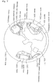
- Fig. 1 is a view showing the display surface of a timepiece according to an embodiment of the present invention, for example, the display surface of a multi-function electronic watch 1000.
- a dial 1002 and a transparent glass 1003 are fitted in the outer case 1001 of the multi-function electronic watch 1000.
- a crown 1101 as the external actuating member of a watch correcting unit is disposed to a portion corresponding to the position of an approximate 4 o'clock of the outer case 1001, and a chronograph start/stop button 1201 and a chronograph reset button 1202 are disposed at the position of an approximate 2 o'clock and at the position of an approximate 10 o'clock position, respectively.
- the ordinary time display unit 1110 of an ordinary time measuring section is disposed to a portion corresponding to the position of an approximate 6 o'clock which is located on an outer peripheral portion spaced apart from the approximate center of the dial 1002 by an arbitrary distance.
- the ordinary time display unit 1110 includes an hour hand 1111, a minute hand 1112, and a second hand 1113 which are ordinary time indicating hands.
- display units including auxiliary hands as chronograph display units are disposed to portions corresponding to the position of an approximate 3 o'clock, the position of an approximate 12 o'clock, and the position of an approximate 9 o'clock which are located on an outer peripheral portion spaced apart from the approximate center of the dial 1002 by an arbitrary distance. That is, a 12 hours display unit 1210 is located at the position of the approximate 3 o'clock of the dial 1002, and an hour chronograph hand 1211 and a minute chronograph hand 1212 are separately disposed on the 12 hours display unit 1210.
- a 60 seconds display unit 1220 is located at the position of the approximate 12 o'clock of the dial 1002 and includes a one second chronograph hand 1221.
- a one second display unit 1230 is located at the position of the approximate 9 o'clock of the dial 1002 and includes a 1/10 second chronograph hand 1231.
- Fig. 2 is a view showing a movement in which mainly shown are the train wheels, the drive units and the like of the ordinary time display unit 1110, the 12 hours display unit 1210, the 60 seconds display unit 1220 and the one second display unit 1230 as the respective display units shown in Fig. 1.
- an ordinary time train wheel 1100G and an ordinary time motor 1300 as an ordinary time drive unit are disposed to portions corresponding to the positions in the approximate 6 o'clock direction of the dial 1002 on the main plate 1701 of the movement 1700.
- a switching unit 1100C is disposed to a portion corresponding to the position of an approximate 4 o'clock of the dial 1002 in the vicinity of the ordinary time train wheel 1100G and the ordinary time motor 1300.
- An IC 1702 as an electric signal output unit having a control circuit 1800 is disposed to a portion corresponding to the position of an approximate 8 o'clock of the dial 1002 in the vicinity of the ordinary time train wheel 1100G and the ordinary time motor 1300.
- a tonometer type quartz resonator 1703 and the like are disposed in the vicinity of the IC 1702.
- a chronograph train wheel 1200G and a chronograph motor 1400 as a chronograph drive unit are disposed to portions corresponding to the position of the approximate 12 o'clock of the dial 1002 and in the direction in the vicinity of the position. Further, a power supply 1500 is disposed in the vicinity of the chronograph train wheel 1200G.
- the ordinary time train wheel 1100G includes a fifth wheel 1121, a second wheel 1122, a third wheel 1123, a center wheel 1124, a minute wheel 1125, an hour wheel 1126 and the like, and an ordinary time second, minute and hour are displayed by the train wheels of them.
- the ordinary time motor 1300 and the chronograph motor 1400 are step motors and composed of coil blocks 1302 and 1402 having magnetic cores composed of a highly permeable material, rotors 1304 and 1404 composed of rotor magnets and rotor pinions, and the like.
- Fig. 3 is a perspective view schematically showing how the train wheel of the ordinary time train wheel 1100G is engaged with the ordinary time motor 1300.
- a rotor pinion 1304 which constitutes the rotor 1304 is meshed with a fifth wheel gear 1121a and a fifth wheel pinion 1121b is meshed with a second wheel gear 1122a. Since a speed reduction ratio from the rotor pinion 1304a to the second wheel gear 1122a is set to 1/30, an electric signal is output from the IC 1702 so that the rotor 1304 is rotated one-half turn in a second. With this operation, the second wheel 1122 is rotated one turn in 60 seconds, whereby an ordinary time second can be displayed by the second hand 1113 fitted to the extreme end of the second wheel 1122.
- a second wheel pinion 1122b is meshed with a third wheel gear 1123a and a third wheel pinion 1123b is meshed with a center wheel gear 1124a. Since a speed reduction ratio from the second wheel pinion 1122b to the center wheel gear 1124a is set to 1/60, the center wheel 1124 is rotated one turn in 60 minutes, whereby an ordinary time minute can be displayed by the minute hand 1112 fitted to the extreme end of the center wheel 1124.
- a center wheel pinion 1124b is meshed with a minute wheel gear 1125a and a minute wheel pinion 1125b is meshed with the hour wheel 1126. Since a speed reduction ratio from the center wheel pinion 1124b to the hour wheel 1126 is set to 1/12, the hour wheel 1126 is rotated one turn in 12 hours, whereby an ordinary time hour can be displayed by the hour hand 1111 fitted to the extreme end of the hour wheel 1126.
- the multi-function electronic watch 1000 arranged as described above is used will be described.
- a user desires to visually confirm an ordinary time, he or she confirms it by looking at the hour hand 1111, the minute hand 1112, and the second hand 1113 of the ordinary time display unit 1110 on the dial 1002.
- the ordinary time display unit 1110 is disposed separately from the respective chronograph display units 1210, 1220, and 1230 as shown in Fig. 1, the user can visually confirm the ordinary time in a state in which his or her field of view is not disturbed by the chronograph indicating hands, and the like.
- the user intends to use the chronograph function of the multi-function electronic watch 1000, he or she uses it by pressing the chronograph start/stop button 1201 and the chronograph reset button 1202.
- the user can obtain the result of the operation by visually confirming the respective hands of the chronograph 12 hours display unit 1210, 60 seconds display unit 1220 and one second display unit 1230.
- the user can confirm the result in the state that his or her field of view is not disturbed by the hands of the ordinary time display unit.
- the ordinary time display unit 1110, the ordinary time train wheel 1100G and the ordinary time motor 1300 can be collectively disposed to the portion corresponding to the approximate 6 o'clock position of the dial 1002 and in the vicinity of it.
- the ordinary time motor 1300 can be located near to the ordinary time display unit 1110. Whereas, when the ordinary time motor 1300 is not located near to the ordinary time display unit 1110 and the distance therebetween is increased, the number of intermediate wheels from the rotor 1304 to the second wheel 1122 must be increased or the diameters of the gear wheels of the rotor 1304, the fifth wheel 1121, and the second wheel 1122 must be increased. A large space is required by this arrangement in any case.
- the disposition of these components in the embodiment can make the ordinary time train wheel 1100G most effectively operative, and the space of the multi-function electronic watch 1000 can be saved as the most remarkable effect of the disposition.
- the IC 1702 having the control circuit 1800 is disposed to the portion corresponding to the position of the approximate 8 o'clock of the dial 1002 as described above, the IC 1702 is prevented from overlapping the ordinary time train wheel 1100G and the other components of the multi-function electronic watch 1000 such as the chronograph train wheel 1200G to be described later, and the like, whereby the thickness of the movement 1700 can be reduced.
- the IC 1702 Since the IC 1702 is prevented from overlapping the ordinary time train wheel 1100G and the chronograph train wheel 1200G as described above, it is not abutted against other parts even if an external disturbance such as a shock is applied thereto. As a result, the IC 1702 itself can be structurally protected.
- the switching unit 1100C as the time correcting unit is disposed to the portion corresponding to the position of the approximate 4 o'clock of the dial 1002 in the vicinity of the ordinary time display unit 1110, the ordinary time train wheel 1100G and the ordinary time motor 1300.
- the switching unit 1100C includes the crown 1101, which is shown in Fig. 1, at an end thereof, and includes a winding stem 1128 having a sliding pinion 1127 fitted thereto, a setting wheel 1129, a setting lever 1131, a setting lever spring 1132, a yoke 1133, and a train wheel setting lever 1130, which are shown in Fig. 2, at the other end thereof.
- the winding stem 1128 is a member for correcting a time and the like externally and set to three states by being pulled out through the crown 1101, that is, a state in which it is pushed most inwardly (zeroth stage), a state in which it is pulled out one stage (first stage), and a state in which it is pulled out two stages (second stage).
- the zeroth stage is in such a state that the ordinary hands are driven on the ordinary time display unit 1110
- the first stage is in such a state that the ordinary hands are driven on the ordinary time display unit 1110 similarly to the zeroth state and a calendar can be corrected
- the second stage is in such a state that the hands are not driven on the ordinary time display unit 1110 and a time can be corrected.
- the winding stem 1128 is a long cylindrical rod having a cut-out formed at a portion thereof, and the extreme end of the setting lever 1131 is engaged with the cut-out.
- the setting lever 1131 is rotated counterclockwise about a setting lever rotating shaft 1131a.
- a click pin 1131b is disposed to a portion of the setting lever 1131, and the click-shaped portion 1132a of the setting lever spring 1132 is engaged with the click pin 1131b.
- click force is generated by the click-shaped portion 1132a as well as positioning of the zeroth, first and second stages is carried out.
- the setting lever 1131 is provided with another operation pin 1131c in confrontation with the click pin 1131b and the setting lever rotating shaft 1131a.
- a yoke 1133 and yoke slot 1133a which is disposed in the shape of a train wheel setting lever 1130, and a train wheel setting lever slot 1130a are engaged with the operation pin 1131c.
- the sliding pinion 1127 is guided by the winding stem 1128 through the center hole thereof and can be rotated together with the rotation of the winding stem 1128.
- the yoke 1133 can be rotated about a yoke rotating shaft 1133b. Further, the extreme end of the yoke 1133 is engaged with a cut-out formed on the sliding pinion 1127. The yoke 1133 moves the sliding pinion 1127 forward and backward, thereby creating a calendar correcting state and a time correcting state.
- the yoke 1133 has a spring portion and always applies force in the direction of the setting lever rotating shaft 1131a of the setting lever 1131.
- the operation pin 1131c of the setting lever 1131 is also rotated thereby.
- the extreme end of the yoke 1133 moves the sliding pinion 1127 toward the outside in the first stage and toward the center in the second stage through the yoke slot 1133a which is engaged with the operation pin 1131c.
- a wheel gear provided with the sliding pinion 1127 is meshed with a backside calendar part to thereby permit a calendar to be corrected.
- the wheel gear disposed at the extreme end of the sliding pinion 1127 is meshed with the setting wheel 1129 to thereby permit a time to be corrected.
- the train wheel setting lever 1130 sets the second wheel 1122 when the time is corrected as well as stops hand operating pulses by inputting a reset signal.
- the train wheel setting lever 1130 is rotated by the rotation of the operation pin 1131c of the setting lever 1131 about the setting lever rotating shaft 1131a along the train wheel setting lever slot 1130a with which it is engaged, thereby setting the second wheel 1122 as well as coming into contact with a reset pattern.
- the shape of the train wheel setting lever slot 1130a escapes the rotational locus of the operation pin 1131c of the setting lever 1131 from the zeroth stage to the first stage as it is.
- the switching unit 1100C is collectively disposed to the portion corresponding to the position of the approximate 4 o'clock of the dial 1002, it does not overlap the ordinary time display unit 1110, the ordinary time train wheel 1100G, the ordinary time motor 1300 and the like.
- the portion corresponding to position of the approximate 4 o'clock of the dial 1002 is very near to the portion corresponding to the position of the approximate 6 o'clock of the dial 1002 where the ordinary time display section 1110, the ordinary time train wheel 1100G, the ordinary time motor 1300 and the like are disposed, the number of the parts of the switching unit 1100 such as a train wheel and the like can be reduced.
- the collective disposition of the crown 1101 of the switching unit 1100C to the portion corresponding to the position of the approximate 4 o'clock of the dial 1002 is effective from the view point of the manipulation performed by the user.
- the winding stem 1128 is pulled out to the second stage by pulling the crown 1101, a reset signal input unit 1130b disposed to the train wheel setting lever 1130 comes into contact with the pattern of a circuit board 1704 on which the IC 1702 is mounted, thereby stopping the output of motor pulses so as to stop driving the hands.
- the rotation of the second wheel gear 1122a is set by the second setting unit 1130a disposed to the train wheel setting lever 1130.
- the center wheel gear 1124a is coupled with the center wheel pinion 1124b with predetermined sliding torque, the setting wheel 1129, the minute intermediate wheel 1131d, the minute wheel 1125, the center wheel pinion 1124b, and the hour wheel 1126 are rotated even if the second wheel 1122 is set. Therefore, an arbitrary time can be set because the minute hand 1112 and the hour hand 1111 are rotated.
- the chronograph train wheel 1200G includes the train wheels of a 1/10 second CG (chronograph) intermediate wheel 1231d, and a 1/10 second CG wheel 1232 which is disposed at the center position of the one second display unit 1230.
- chronograph 1/10 second is displayed at the portion corresponding to the position of the approximate 9 o'clock of the dial 10002.
- the chronograph train wheel 1200G includes the train wheels of a one second CG first intermediate wheel 1221d, a one second CG second intermediate wheel 1222d, and a one second CG wheel 1223 which is disposed at the center position of the 60 seconds display unit 1220. With the arrangement of the train wheels, a chronograph second is displayed at the portion corresponding to the position of the approximate 12 o'clock of the dial 10002.
- the chronograph train wheel 1200G includes the train wheels of a minute CG first intermediate wheel 1211d, a minute CG second intermediate wheel 1212d, a minute CG third intermediate wheel 1213d, a minute CG fourth intermediate wheel 1214d, an hour CG intermediate wheel 1215d, a minute CG wheel 1216, and an hour CG wheel 1217.
- the minute CG wheel 1216 and the hour CG wheel 1217 are concentrically disposed at the center position of the 12 hours display unit 1210. With the arrangement of the train wheels, a chronograph hour and minute are displayed at a portion corresponding to the position of the approximate 3 o'clock of the dial 1002.
- Fig. 4 is a side sectional view showing how a 1/10 second display train wheel of the chronograph train wheel 1200G is engaged.
- a rotor pinion 1404a is meshed with a 1/10 second CG intermediate wheel gear 1231a which is meshed with a 1/10 second CG wheel gear 1232a. Since a speed reduction ratio from the rotor pinion 1404a to the 1/10 second CG wheel gear 1232a is set to 1/5, the IC 1702 outputs an electric signal so that the rotor 1404 is rotated one-half turn in 1/10 second. Thus, the 1/10 second CG wheel 1232 is rotated one turn in a second, and chronograph 1/10 second can be displayed by the 1/10 second chronograph hand 1231 fitted to the extreme end of the 1/10 second CG wheel 1232.
- Fig. 5 is a side sectional view showing how a one second display train wheel of the chronograph train wheel 1200G is engaged.
- the 1/10 second CG intermediate wheel gear 1231a is meshed with a one second CG first intermediate wheel gear 1221a, and a one second CG first intermediate wheel pinion 1221b is meshed with a one second CG second intermediate wheel gear 1222a. Further, a one second CG second intermediate wheel pinion 1222b is meshed with a one second CG gear wheel 1223a.
- the 1/10 second CG intermediate wheel gear 1231a is meshed with the rotor pinion 1404a as described above, and a speed reduction ratio from the rotor pinion 1404a to the one second CG gear wheel 1223a is set to 1/300. Therefore, the one second CG wheel 1223 is rotated one turn in 60 seconds, and a chronograph one second can be displayed by the one second chronograph hand 1221 fitted to the extreme end of the one second CG wheel 1223.
- Fig. 6 is a side sectional view showing how an hour and minute display train wheel of the chronograph train wheel 1200G is engaged.
- the one second CG second intermediate wheel gear 1222a is meshed with a minute CG first intermediate wheel gear 1211a which is meshed with a minute CG second intermediate wheel gear 1212a. Further, a minute CG second intermediate wheel pinion 1212b is meshed with a minute CG third intermediate wheel gear 1213a, and a minute CG third intermediate wheel pinion 1213b is meshed with a minute CG fourth intermediate wheel gear 1214a. Further, a minute CG fourth intermediate wheel pinion 1214b is meshed with a minute CG wheel 1216a.
- a minute CG wheel pinion 1216b is meshed with an hour CG intermediate wheel gear 1215a
- an hour CG intermediate wheel pinion 1215b is meshed with an hour CG wheel gear 1217a. Note that, in Fig. 3 to Fig. 5, since a speed reduction ratio from the rotor 1404 to the minute CG wheel gear 1216a is set to 1/18000, the minute CG wheel 1216 is rotated one turn in 60 minutes and a chronograph minute can be displayed by the minute chronograph hand 1212 fitted to the extreme end of the minute CG wheel 1216.
- a speed reduction ratio from the minute CG wheel pinion 1216b to the hour CG wheel gear 1217a is set to 1/12
- the hour CG wheel 1217 is rotated one turn in 12 hours, and a chronograph hour can be displayed by the hour chronograph hand 1211 fitted to the extreme end of the hour CG wheel 1217.
- the one second display unit 1230, the 60 seconds display unit 1220, the hour chronograph 1211 and the minute chronograph 1212 are disposed to the portions corresponding to the positions of the approximate 10 o'clock, the approximate 12 o'clock and the approximate 2 o'clock of the dial 1002, respectively. Then, the train wheels and the like are disposed in the vicinity of them in correspondence to them. Further, as described above, the chronograph motor 1400 as the chronograph drive unit is disposed to the portion corresponding to the position of the approximate 9 o'clock to the position of the approximate 12 o'clock of the dial 1002 which are located in the vicinity of the train wheels and the like.
- the chronograph motor 1400 operates the one second display unit 1230, the 60 seconds display unit 1220, and the train wheels of the hour chronograph 1211 and the minute chronograph 1212, when the chronograph motor 1400 is disposed to the portion corresponding to the position of the approximate 9 to the position of the approximate 12 o'clock, the drive force of the motor can be transmitted in the following sequence.
- the drive force is transmitted from the one second display unit 1230 to the 60 seconds display unit 1220, and then transmitted to the hour chronograph hand 1211 through the minute chronograph hand 1212.
- the chronograph motor 1400 is disposed to other position, the distance from the one second display unit 1230 to the hour chronograph 1211 is increased, whereby the number of train wheels arranged in the intermediate portion therebetween is increased or the diameters of the wheel gears are increased.
- the embodiment can minimize the number of the train wheels as well as optimize gear diameters, whereby a remarkable effect of saving the space of the multi-function electronic watch 1000 can be achieved.
- circuit board 1704 of the multi-function electronic watch 1000 will be described.
- the circuit board 1704 shown in Fig. 7 is, for example, a flexible print board and disposed on the movement 1700 shown in Fig. 2.
- the IC 1702, the tonometer type quartz resonator 1703 and the like are mounted on the circuit board 1704. Then, drive pulses of an ordinary time and a chronograph are generated by the IC 1702 and transmitted to the coil blocks 1302 and 1402 of the respective motors 1300 and 1400 connected to a not shown copper foil pattern.
- the power supply 1500 is disposed to a portion corresponding to the position of the approximate 1 hour to the position of the approximate 12 o'clock of the dial 1002.
- the positive terminal of the power supply 1500 is connected to the circuit board 1704 in such a manner that the extreme end spring portion of a positive terminal 1502, which is guided by a pin 1501 fitted into the main plate 1701 composed of a metal, comes into contact with the side of the button type secondary power supply 1500 with predetermined spring force, a positive lead plate 1503 comes into contact with the extreme end of the pin 1501, and further extreme end spring portion of the positive lead plate 1503 comes into contact with the positive pattern of the circuit board 1704 with predetermined spring force.
- the positive voltage is supplied through the power supply 1500 ⁇ the positive terminal 1502 ⁇ the main plate 1701 ⁇ the pin 1501 ⁇ the positive lead plate 1503 ⁇ the positive pattern of the circuit board 1704 ⁇ the IC 1702. Further, the negative voltage of the power supply 1500 is connected to the circuit board 1704 in such a manner that a spring portion, which is disposed to the outer periphery of a negative terminal 1504 welded and conducted to the end surface of the power supply 1500, comes into contact with the negative pattern of the circuit board 1704 with predetermined spring force.
- the negative voltage is supplied through the power supply 1500 ⁇ the negative terminal 1504 ⁇ the negative pattern of the circuit board 1704 ⁇ the IC 1702.
- the power supply 1500 is disposed to the portion corresponding to the position of the approximate 1 o'clock to the position of the approximate 12 o'clock of the dial 1002.
- the ordinary time motor 1300 is mounted to the portion corresponding to the position of the approximate 6 o'clock of the dial 1002
- the chronograph motor 1400 is mounted to the portion corresponding to the position of the approximate 9 o'clock to the position of the 12 o'clock of the dial 1002.
- the IC 1702 is disposed to the portion corresponding to the position of the approximate 8 o'clock of the dial 1002.
- the power supply 1500 which is a relatively heavy part in the parts of the multi-function electronic watch 1000, is disposed at a position spaced apart from the ordinary time motor 1300, the chronograph motor 1400 and the IC 1702 so that it does not adversely affect them. Therefore, even if the multi-function electronic watch 1000 is dropped, the other parts are prevented from being directly affected by the weight of the power supply 1500, whereby the reliability of the electronic watch 1000 can be enhanced.
- the ordinary time motor 1300 is mounted to the portion corresponding to the position of the approximate 6 o'clock position of the dial 1002
- the chronograph motor 1400 is mounted to the portion corresponding to the position of the approximate 9 o'clock to the position of the approximate 12 o'clock of the dial 1002. Therefore, the wiring distance from the IC 1702 mounted on the circuit board 1704 to the ordinary time motor 1300 and the chronograph motor 1400 can be shortened, whereby the area of the circuit board 1704 and the like can be reduced.
- the thickness and size of the multi-function electronic watch 1000 can be reduced as well as the user can visually confirm the ordinary time display 1110 and the chronograph displays 1210, 1220, and 1230 in the state that they do not overlap each other.
- the multi-function electronic watch 1000 having the dial 1002 which the user can visually confirm easily.
- a power generating unit may be mounted on the multi-function electronic watch 1000.
- the arrangement of the above multi-function electronic watch 1000 is disposed on a first layer and the power generating unit and the like are disposed as a second layer.
- the present invention is not particularly limited thereto and analog display type multi-function time measurement may be applied to a timepiece.
- the timepiece whose thickness and size are reduced and which can be visually confirmed by the user easily. Further, according to the present invention, the user of the timepiece can visually confirm the ordinary time display unit and the chronograph display unit easily as well as the thickness and the size of the timepiece having the chronograph function can be reduced.
- the thickness and size of the timepiece can be more reduced.
- the ordinary time display unit and the chronograph display units are separately disposed to the outer peripheral portion of the timepiece which has the arbitrary distance from the approximate center of the timepiece, the parts constituting the display units are not overlapped and increased in the thickness thereof, whereby an increase in the thickness of the timepiece can be prevented in its entirety.
- the user of the timepiece can visually confirm the ordinary time display unit easily.
- the user of the timepiece can instantly read the entire chronograph display unit.
- the ordinary time motor is disposed near to the ordinary time display unit, the number of the components constituting the ordinary time train wheel can be minimized as well as the diameters of the wheel gears thereof can be reduced, whereby the size of the timepiece can be reduced.
- the chronograph motor is disposed near to the chronograph display unit, the number of the components constituting the chronograph train wheels can be minimized as well as the diameters of the wheel gears thereof can be reduced, whereby the size of the timepiece can be reduced.
- the chronograph display unit can be driven by only one motor, the space in the timepiece can be reduced, whereby a cost can be reduced. Further, it is possible to accurately display the chronograph.
- the power supply it is difficult for the power supply to adversely affect the ordinary time motor, the ordinary time train wheel, the chronograph motor, the chronograph train wheels, and the like even if the timepiece is dropped, the adverse affect of the weight of the power supply on the other parts can be avoided, whereby the reliability of the timepiece is enhanced. Even if the timepiece is encountered with an external disturbance, the other parts such as the ordinary time motor and the like are not adversely affected by the relatively heavy power supply unit, that is, they are not subjected to breakage and the like.
- the thickness of the timepiece can be reduced as well as the electric signal output unit which is relatively less strong can be prevented from being broken by the external disturbance such as a shock and the like, whereby the reliability of the timepiece can be enhanced.
- the time correcting unit can be disposed to a portion where the user can easily manipulate it.
- the timepiece can be designed so that the space thereof can be effectively used as well as the number of the components of the time correcting unit can be minimized.
- Fig. 11 is a schematic block view showing the arrangement of an embodiment of a timepiece of the present invention.
- a timepiece 1000 shown in Fig. 11 is an analog electronic watch having a chronograph function.
- a timepiece main body 1000B is divided into a plurality of layers (two layers in the figure) in a side (thickness) direction.
- an ordinary time measuring section 1100 for measuring an ordinary time and a time information measuring section 1200 for measuring time information other than the ordinary time are disposed on a first layer, and a reset to zero mechanism 1200R for resetting the measurement of the time information other than the ordinary time to zero and a power generating unit 1600 for converting mechanical energy into electric energy and generating a drive voltage for driving the ordinary time measuring section 1100 and the time information measuring section 1200 and disposed on a second layer.
- the division of the timepiece main body 1000B into the two layers and the separate disposition of the respective components 1100, 1200, 1200R, and 1600 to the respective layers permit the size of the timepiece 1000 to be reduced in the plane (lateral) direction thereof.
- timepiece 1000 resides in the structure of the periphery of the power generating unit 1600, which will be described later (Figs. 21 and 24).
- Fig. 12 is a view showing the arrangement of a detailed example of the interior of the timepiece main body 1000B of the timepiece 1000 shown in Fig. 11.
- the ordinary time measuring section 1100 includes, as the components thereof, an ordinary time display unit 1110 for displaying an ordinary time by hands, a motor 1300 for driving the hands of the ordinary time display unit 1110, an ordinary time train wheel 1100G for transmitting the drive force of the motor 1300 to the hands of the ordinary time display unit 1110, and a switching unit 1100C for switching the time and the calendar of the ordinary time display unit 1110 to a correcting state.
- the time information measuring section 1200 includes, as the components thereof, a 12 hours display unit 1210 for displaying 12 hours with a hand, a 60 seconds display unit 1220 for displaying 60 seconds with a hand, a one second display unit 1230 for displaying one second with a hand, a motor 1400 for driving the hands of the respective display units 1210, 1220, and 1230, and a chronograph train wheel 1200G for transmitting the drive force of the motor 1400 to the hands of the respective display units 1210, 1220, and 1230.
- the ordinary time measuring section 1100 and the time information measuring section 1200 include a secondary power supply 1500 for supplying electric power for driving the respective motors 1300 and 1400 and a control circuit 1800 for controlling them in their entirety as components common to them.
- the power generating unit 1600 includes, as the components thereof, an oscillating weight 1605 for obtaining mechanical energy and a power generating mechanism 1601 for converting the mechanical energy into electric energy and storing it in the secondary power supply 1500.
- the motors 1300 and 1400 are individually driven using the electric power generated by the power generating unit 1600 so as to drive the hands of the ordinary time measuring section 1100 and the time information measuring section 1200.
- the hands of the respective display units 1210, 1220 and 1230 are mechanically reset to zero by the reset to zero mechanism 1200R without being driven by a motor as described later.
- the first layer is partitioned from the second layer by a first intermediate receiving plate 2001, a second intermediate receiving plate 2002 and a third intermediate receiving plate 2003 which are disposed in a plane (lateral) direction.
- a main plate 1701 is disposed on the first layer by being spaced apart from the respective receiving plates 2001, 2002, and 2003, and an upper receiving plate 2010 is disposed on the second layer by being spaced apart from the respective intermediate receiving plates 2001, 2002, and 2003.
- a so-called movement 1700 is interposed between the respective intermediate receiving plate 2001, 2002, and 2003 and the main plate 1701. That is, the ordinary time train wheel 1100G is interposed between the first intermediate receiving plate 2001 and the main plate 1701, the switching unit 1100C, the motor 1300 and the control circuit 1800 are interposed between the second intermediate receiving plate 2002 and the main plate 1701, and the secondary power supply 1500, the motor 1400 and the chronograph train wheel 1200G are interposed between the third intermediate receiving plate 2003 and the main plate 1701. Then, a circuit board 1704 is disposed on the motor 1300, the control circuit 1800, the secondary power supply 1500 and the motor 1400. Further, the ordinary time display unit 1110 is disposed on the main plate 1701 and the respective display units 1210, 1220 and 1230 are disposed on a dial 1002 shown in Fig. 13.
- the power generating mechanism 1601 is interposed between the second intermediate receiving plate 2002 and the upper receiving plate 2010, and the reset to zero mechanism 1200R is interposed between the third intermediate receiving plate 2003 and the upper receiving plate 2010. Then, an oscillating weight 1605 is disposed on the upper receiving plate 2010.
- Fig. 13 is a plan view showing the respective display units 1110, 1210, 1220, and 1230 constituting the first layer of the timepiece 1000 shown in Figs. 11 and 12 when they are viewed from the surface side of the timepiece 1000.
- the timepiece 1000 is arranged such that the dial 1002 is assembled to the movement 1700 and a transparent glass 1003 is fitted in the interior of an outer case 1001.
- a crown 1101 as an external manipulating member is disposed at the position a 4 o'clock of the outside case 1001, and a chronograph start/stop button 1201 and a chronograph reset button 1202 are disposed at the positions of an approximate 2 o'clock and an approximate 10 o'clock.
- the ordinary time display unit 1110 including an hour hand 1111, a minute hand 1112, and a second hand 1113 which are ordinary time hands is disposed at the position of an approximate 6 o'clock of the dial 1002, and the display units 1210, 1220, and 1230 having chronograph auxiliary hands are disposed at the positions of an approximate 3 o'clock, an approximate 12 o'clock and an approximate 9 o'clock.
- the 12 hours display unit 1210 having hour and minute chronograph hands 1211 and 1212 are disposed at the position of the approximate 3 o'clock
- the 60 seconds display unit 1220 having a one second chronograph hand 1221 is disposed at the position of the approximate 12 o'clock
- the one second display unit 1230 having a 1/10 chronograph hand 1231 is disposed at the position of the approximate 9 o'clock.
- Fig. 14 is a plan view showing the movement 1700 constituting the first layer of the timepiece 1000 shown in Figs. 11 and 12 excluding the circuit board 1704 constituting the first layer when it is viewed from the backside of the timepiece.
- the ordinary time train wheel 1100G, the motor 1300, the switching unit 1100C and an IC 1702 constituting the control circuit 1800, a tonometer type quartz resonator 1703, a large capacity capacitor 1814 and the like are disposed on the main plate 1701 in a 6 o'clock direction side, and the chronograph train wheel 1200G, the motor 1400 and the secondary power supply 1500 such as a lithium ion power supply and the like are disposed on the main plate 1701 in a 12 o'clock direction side.
- the ordinary time train wheel 1100G includes the train wheel of a fifth wheel 1121, a second wheel 1122, a third wheel 1123, a center wheel 1124, a minute wheel 1125, and an hour wheel 1126, and a second display, a minute display and an hour display of an ordinary time are carried out by the train wheel.
- the motors 1300 and 1400 are step motors and composed of coil blocks 1302 and 1402 having magnetic cores composed of a highly permeable material, stators 1303 and 1403 composed of a highly permeable material, rotors 1304 and 1404 composed of rotor magnets and rotor pinions, and the like.
- Fig. 15 is a perspective view schematically showing how the train wheel of the ordinary time train wheel 1100G is engaged with the motor 1300.
- a rotor pinion 1304a which constitutes the rotor 1304 is meshed with a fifth wheel gear 1121a and a fifth wheel pinion 1121b is meshed with a second wheel gear 1122a. Since a speed reduction ratio from the rotor pinion 1304a to the second wheel gear 1122a is set to 1/30, an electric signal is output from the IC 1702 so that the rotor 1304 to be rotated one-half turn in one second. With this operation, the second wheel 1122 is rotated one turn in 60 seconds, whereby an ordinary time second can be displayed by the second hand 1113 fitted to the extreme end of the second wheel 1122.
- a second wheel pinion 1122b is meshed with a third wheel gear 1123a and a third wheel pinion 1123b is meshed with a center wheel gear 1124a. Since a speed reduction ratio from the second wheel pinion 1122b to the center wheel gear 1124a is set to 1/60, the center wheel 1124 is rotated one turn in 60 minutes, whereby an ordinary time minute can be displayed by the minute hand 1112 fitted to the extreme end of the center wheel 1124.
- a center wheel pinion 1124b is meshed with a minute wheel gear 1125a which is meshed with the hour wheel 1126. Since a speed reduction ratio from the center wheel pinion 1124b to the hour wheel 1126 is set to 1/12, the hour wheel 1126 is rotated one turn in 12 hours, whereby an ordinary time hour can be displayed by the hour hand 1111 fitted to the extreme end of the hour wheel 1126.
- the switching unit 1100C includes the crown 1101, which is shown in Fig. 13 at an end thereof, and includes a winding stem 1128 to which a sliding pinion 1127 is fitted, a setting wheel 1129, a setting lever 1131, a setting lever spring 1132, a yoke 1133, and a train wheel setting lever 1130 at the other end thereof.
- the winding stem 1128 is a member for correcting a time and the like externally and set to three states by being pulled out by the crown 1101, that is, a state in which it is pushed most inwardly (zeroth stage), a state in which it is pulled out one stage (first stage), and a state in which it is pulled out two stages (second stage).
- the zeroth stage is in such a state that the ordinary hands are driven on the ordinary time display unit 1110
- the first stage is in such a state that the ordinary hands are driven on the ordinary time display unit 1110 similarly to the zeroth state and a calendar can be corrected
- the second stage is in such a state that the hands are not driven on the ordinary time display unit 1110 and a time can be corrected.
- the winding stem 1128 is a long columnar rod having a cut-out formed at a portion thereof, and the extreme end of the setting lever 1131 is engaged with the cut-out.
- the setting lever 1131 is rotated counterclockwise about a setting lever rotating shaft 1131a.
- a click pin 1131b is disposed to a portion of the setting lever 1131, and the click-shaped portion 1132a of the setting lever spring 1132 is engaged with the click pin 1131b.
- click force is generated by the click-shaped portion 1132a as well as positioning of the zeroth, first and second stages is carried out.
- the setting lever 1131 is provided with another operation pin 1131c in confrontation with the click pin 1131b and the setting lever rotating shaft 1131a.
- a yoke slot 1133a and a yoke slot 1130a which is disposed in the shape of the yoke 1133, and the train wheel setting lever 1130, are engaged with the operation pin 1131c.
- the sliding pinion 1127 is guided by the winding stem 1128 through the center hole thereof and can be rotated together with the rotation of the winding stem 1128.
- the yoke 1133 can be rotated about a yoke rotating shaft 1133b. Further, the extreme end of the yoke 1133 is engaged with a cut-out formed on the sliding pinion 1127. The yoke 1133 moves the sliding pinion 1127 forward and backward, thereby creating a calendar correcting state and a time correcting state.
- the yoke 1133 has a spring portion and always applies force in the direction of the setting lever rotating shaft 1131a of the setting lever 1131. When the setting lever 1131 is rotated, the operation pin 1131c of the setting lever 1131 is also rotated thereby.
- the extreme end of the yoke 1133 moves the sliding pinion 1127 toward the outside in the first stage and toward the center in the second stage through the yoke slot 1133a which is engaged with the operation pin 1131c.
- a wheel gear provided with the sliding pinion 1127 is meshed with a backside calendar part to thereby permit a calendar to be corrected.
- the wheel gear disposed at the extreme end of the sliding pinion 1127 is meshed with the setting wheel 1129 to thereby permit a time to be corrected.
- the train wheel setting lever 1130 sets the second wheel 1122 when a time is corrected as well as stops hand operating pulses by inputting a reset signal. Likewise the yoke 1133, the train wheel setting lever 1130 is rotated by the rotation of the operation pin 1131c of the setting lever 1131 about a train wheel setting lever rotating shaft 1130b along the train wheel setting lever slot 1130a with which it is engaged, thereby setting the second wheel 1122 as well as coming into contact with a reset pattern. Since it is sufficient that the action of the train wheel setting lever 1130 is applied only in the second stage, the shape of the train wheel setting lever slot 1130a escapes the rotational locus of the operation pin 1131c of the setting lever 1131 from the zeroth stage to the first stage as it is.
- the winding stem 1128 is pulled to the second stage by pulling the crown 1101, a reset signal input section 1130b disposed to the train wheel setting lever 1130 comes into contact with the pattern of a circuit substrate 1704 on which the IC 1702 is mounted, thereby stopping the output of motor pulses so as to stop the operation of the hands.
- the rotation of the fourth wheel gear 1122a is set by the train wheel setting lever slot 1130a disposed to the train wheel setting lever 1130.
- the center wheel gear 1124a is coupled with the center wheel pinion 1124b with predetermined sliding torque, the setting wheel 1129, the minute wheel 1125, the center wheel pinion 1124b, and the hour wheel 1126 are rotated even if the second wheel 1122 is set. Therefore, an arbitrary time can be set because the minute hand 1112 and the hour hand 1111 are rotated.
- the chronograph train wheel 1200G includes the train wheels of a 1/10 second CG (chronograph) intermediate wheel 1231 and a 1/10 second CG wheel 1232 which is disposed at the center position of the one second display unit 1230. With the above arrangement of the train wheels, chronograph 1/10 second is displayed at the position the 9 o'clock of the watch.
- the chronograph train wheel 1200G includes the train wheels of a one second CG first intermediate wheel 1221, a one seccnd CG second intermediate wheel 1222, and a one second CG wheel 1223 which is disposed at the center position of the 60 seconds display unit 1220. With the above arrangement of the train wheels, a chronograph second is displayed at the position of the 12 o'clock of the watch.
- the chronograph train wheel 1200G includes the train wheels of a minute CG first intermediate wheel 1211, a minute CG second intermediate wheel 1212, a minute CG third intermediate wheel 1213, a minute CG fourth intermediate wheel 1214, an hour CG intermediate wheel 1215, a minute CG wheel 1216, and an hour CG wheel 1217.
- the minute CG wheel 1216 and the hour CG wheel 1217 are concentrically disposed at the center position of the 12 hours display unit 1210. With the above arrangement of the train wheels, a chronograph minute and hour are displayed at the position of the 3 o'clock of the watch.
- Fig. 6 is a side sectional view showing how a 1/10 second display train wheel of the chronograph train wheel 1200G is engaged.
- a rotor pinion 1404a is meshed with a 1/10 second CG intermediate wheel gear 1231a which is meshed with a 1/10 second CG wheel gear 1232a. Since a speed reduction ratio from the rotor pinion 1404a to the 1/10 second CG wheel gear 1232a is set to 1/5, the IC 1702 outputs an electric signal so that the rotor 1404 is rotated one-half turn in 1/10 second. Thus, the 1/10 second CG wheel 1232 is rotated one turn in a second, and chronograph 1/10 second can be displayed by the 1/10 second chronograph hand 1231 fitted to the extreme end of the 1/10 second CG wheel 1232.
- Fig. 17 is a side sectional view showing how a one second display train wheel of the chronograph train wheel 1200G is engaged.
- the 1/10 second CG intermediate wheel gear 1231a is meshed with a one second CG first intermediate wheel gear 1221a, and a one second CG first intermediate wheel pinion 1221b is meshed with a one second CG second intermediate wheel gear 1222a. Further, a one second CG second intermediate wheel pinion 1222b is meshed with a one second CG gear wheel 1223a.
- the 1/10 second CG intermediate wheel gear 1231a is meshed with the rotor pinion 1404a as described above, and a speed reduction ratio from the rotor pinion 1404a to the one second CG gear wheel 1223a is set to 1/300. Therefore, the one second CG wheel 1223 is rotated one turn in 60 seconds, and a chronograph one second can be displayed by the one second chronograph hand 1221 engaged with the extreme end of the one second CG wheel 1223.
- Fig. 18 is a side sectional view showing how an hour and minute display train wheel of the chronograph train wheel 1200G is engaged.
- the one second CG second intermediate wheel gear 1222a is meshed with the minute CG first intermediate wheel gear 1211a which is meshed with a minute CG second intermediate wheel gear 1212a. Further, a minute CG second intermediate wheel pinion 1212b is meshed with a minute CG third intermediate wheel gear 1213a, and a minute CG third intermediate wheel pinion 1213b is meshed with a minute CG fourth intermediate wheel gear 1214a. Furthermore, a minute CG fourth intermediate wheel pinion 1214b is meshed with the minute CG wheel 1216a. In addition, a minute CG wheel pinion 1216b is meshed with an hour CG intermediate wheel gear 1215a, and an hour CG intermediate wheel pinion 1215b is meshed with an hour CG wheel gear 1217a.
- Fig. 19 is a plan view showing the circuit board 1704 constituting the first layer of the timepiece 1000 shown in Figs. 11 and 12 when it is viewed from the backside of the timepiece, wherein only the parts electrically connected to the circuit board 1704 are shown.
- the circuit board 1704 shown in Fig. 19 is, for example, a flexible print board and disposed on the movement 1700 shown in Fig. 14.
- the IC 1702, the tonometer type quartz resonator 1703, the large capacity capacitance 1814 and the like are mounted on the circuit board 1704. Then, drive pulses of an ordinary time and a chronograph are generated by the IC 1702 and transmitted to the coil blocks 1302 and 1402 of the respective motors 1300 and 1400.
- the positive terminal of the secondary power supply 1500 is connected to the circuit board 1704 in such a manner that the extreme end spring portion of a positive terminal 1502, which is guided by a pin 1501 fitted into the main plate 1701 composed of a metal, comes into contact with the side of the button type secondary power supply 1500 with predetermined spring force, a positive lead plate 1503 comes into contact with the extreme end of the pin 1501, and further extreme end spring portion of the positive lead plate 1503 comes into contact with the positive pattern of the circuit board 1704 with predetermined spring force. Therefore, the positive voltage is supplied through the secondary power supply 1500 ⁇ the positive terminal 1502 ⁇ the pin 1501 ⁇ the positive lead plate 1503 ⁇ the positive pattern of the circuit board 1704 ⁇ the IC 1702.
- the negative voltage of the secondary power supply 1500 is connected to the circuit board 1704 in such a manner that a spring portion, which is disposed to the outer periphery of a negative terminal 1504 welded and conducted to the end surface of the secondary power supply 1500, comes into contact with the negative pattern of the circuit board 1704 with predetermined spring force. Therefore, the negative voltage is supplied through the secondary power supply 1500 ⁇ the negative terminal 1504 ⁇ the negative pattern of the circuit board 1704 ⁇ the IC 1702.
- an insulating plate 1505 is mounted on the negative terminal 1504 to prevent the short-circuit of the negative terminal 1504 to the third intermediate receiving plate 2003.
- Fig. 20 is a plan view showing the first intermediate receiving plate 2001, the second intermediate receiving plate 2002, and the third intermediate receiving plate 2003 for dividing the first layer of the timepiece 1000 shown in Figs. 11 and 12 from the second layer when they are viewed from the backside of the timepiece 1000.
- the first intermediate receiving plate 2001 is disposed to the outermost side in a 6 o'clock direction side so as to cover the motor 1300, the switching unit 1100C, the tonometer type quartz resonator 1703 which constitutes the control circuit 1800, the large capacity capacitance 1814, and the like.
- the second intermediate receiving plate 2002 is disposed inwardly of the first intermediate receiving plate 2001 so as to cover the ordinary time train wheel 1100G, the IC 1702 which constitutes the control circuit 1800, and the like.
- the third intermediate receiving plate 2003 is disposed in a 12 o'clock direction side so as to cover the chronograph train wheel 1200G, the motor 1400, the secondary power supply 1500 such as the lithium ion power supply, and the like.
- Fig. 21 is a plan view showing the power generating unit 1600 (power generating mechanism 1601), which constitutes the second layer of the timepiece shown in Figs. 11 and 12 excluding the oscillating weight 1605, and the reset to zero mechanism 1200R when they are viewed from the backside of the timepiece 1000.
- the power generating mechanism 1601 shown in Fig. 21 is disposed on the second intermediate receiving plate 2002 shown in Fig. 20, and the reset to zero mechanism 1200R is disposed on the second intermediate receiving plate 2002 and the third intermediate receiving plate 2003 shown in Fig. 20 extending therebetween.
- the power generating unit 1600 shown in Figs. 22 and 23 is composed of a power generating coil 1602 wound around a highly permeable material, a power generating stator 1603 composed of a highly permeable material, a power generating rotor 1604 composed of a permanent magnet and a wheel pinion unit, a one-sided oscillating weight 1605 disposed on the upper receiving plate 2010 and the like.
- the oscillating weight 1605 and the oscillating weight wheel 1606 disposed below the oscillating weight 1605 are rotatably journaled by a shaft fixed to the upper receiving plate 2010, and the removal of them in an axial direction is prevented by an oscillating weight screw 1607.
- the oscillating weight wheel 1606 is meshed with the wheel pinion unit 1608a of a power generating rotor transmission wheel 1608, and the gear portion 1608b of the power generating rotor transmission wheel 1608 is meshed with the wheel pinion unit 1604a of the power generating rotor 1604.
- the speed of the train wheel is increased from 30 times to about 200 times.
- the speed increasing ratio can be optionally set in accordance with the capability of the power generating unit the specification of the watch.
- the power generating rotor 1604 when the oscillating weight 1605 is rotated by the motion of the wrist of a user, or the like, the power generating rotor 1604 is rotated at a high speed. Since the permanent magnet is fixed to the power generating rotor 1604, the direction of magnetic flux which is obliquely across the power generating coil 1602 through the power generating stator 1603 is changed each time the power generating rotor 1604 is rotated, whereby an alternating voltage is generated to the power generating coil 1602 by electromagnetic induction. The alternating voltage is rectified by a rectifying circuit 1609 mounted on the circuit board 1704 and charged to the secondary power supply 1500.
- the power generating coil 1602 is connected to a conductive pattern formed on a conduction board 1611 through a lead pattern formed on a coil lead board 1610. Both the surfaces of the conduction board 1611 is held between a conductive press plate 1621 disposed on the upper receiving plate 2010 side and a conduction guide seat 1613 disposed on the second intermediate receiving plate 2002.
- a through hole is formed from the conduction guide seat 1613 to the second intermediate receiving plate 2002, and the conduction pattern formed on the conduction board 1611 is connected to the power supply pattern formed on the circuit board 1704 through a conduction spring (compression coil spring) 1614 inserted into the through hole. Therefore, the alternating voltage is supplied from the power generating unit 1600 to the secondary power supply 1500 through the power generating coil 1602 ⁇ the lead pattern of the coil lead board 1610 ⁇ the conduction pattern of the conduction board 1611 ⁇ the conduction spring 1614 ⁇ the power supply pattern of the circuit board 1704 ⁇ the secondary power supply 1500.
- both the ends of the conduction spring 1614 come into intimate contact with the conduction pattern of the conduction board 1611 and the power supply pattern of the circuit board 1704, whereby the reliability of conduction can be enhanced.
- the power generating mechanism 1601 is covered with a magnetic screen 1615 disposed to the upper receiving plate 2010 side.
- the influence of a magnetic field on the motor 1300, which is caused by power generation, can be reduced by covering the power generating mechanism 1601 with the magnetic screen 1615. Note that the same effect or a higher effect also can be achieved by covering the power generating mechanism 1601 with the magnetic screen 1615 which is disposed on the second intermediate receiving plate 2002 side or on the upper receiving plate 2010 side and the second intermediate receiving plate 2002 side.
- Fig. 25 is a side sectional view showing an example of the schematic arrangement of the main portion of the reset to zero mechanism 1200R. Note that the reset to zero mechanism 1200R shown in Fig. 21 shows a reset state, whereas the reset to zero mechanism 1200R shown in Fig. 25 shows a stop state.
- the reset to zero mechanism 1200R mechanically is started/stopped and reset by the rotation of an actuation cam 1240 which is disposed at an approximate center.
- the actuation cam 1240 is formed in a cylindrical shape and has tooth 1240a formed on the side along the periphery thereof at a predetermined pitch and columns 1240b formed along the periphery of an end surface thereof at a predetermined pitch.
- the phase thereof is regulated by an actuation cam jumper 1241 which is locked between tooth 1240a and rotated counterclockwise by an actuation cam rotating unit 1242d disposed at the extreme end of an actuation lever 1242.
- a start/stop actuation mechanism is composed of an actuation lever 1242, a switch lever A 1243 and a operating lever spring 1244.
- the actuation lever 1242 is formed in an approximately flat-L-shape. An end of it is provided with a bent press section 1242a, an oval through hole 1242b and a pin 1242c and the other end of it is provided with an acute press section 1242d at the extreme end thereof.
- the actuation lever 1242 is arranged as a start/stop actuation mechanism in such a manner that the press section 1242d is caused to be in confrontation with the start/stop button 1201, a pin 1242e fixed to the third intermediate receiving plate 2003 is inserted into the through hole 1242b, an end of the operating lever spring 1244 is locked to the pin 1242c and the press section 1242d is disposed in the vicinity of the actuation cam 1240.
- An end of the switch lever A 1243 is arranged as a switch section 1243a, an approximate center thereof is provided with a flat projection 1243b and the other end thereof is formed as a locking section 1243c.
- the switch lever A 1243 is arranged as the start/stop actuation mechanism in such a manner that the approximate center thereof is rotatably journaled by a pin 1243d fixed to the third intermediate receiving plate 2003, the switch section 1243a is disposed in the vicinity of the start circuit of the circuit board 1704, the projection 1243b is disposed to come into contact with columns 1240b disposed in the axial direction of the actuation cam 1240 and the locking section 1243c is locked to a pin 1243e fixed to the third intermediate receiving plate 2003.
- the switch section 1243a of the switch lever A 1243 is turned on by being caused to come into contact with the start circuit of the circuit board 1704.
- the switch lever A 1243 which is electrically connected to the secondary power supply 1500 through the main plate 1701 and the like, has the same potential as that of the positive pole of the secondary power supply 1500.
- the actuation lever 1242 when the chronograph is in a stop state, the actuation lever 1242 is positioned in the state in which the press section 1242a is separated from the start/stop button 1201, the pin 1242c is pressed in the direction of an illustrated arrow a by the elastic force of the operating lever spring 1244, and an end of the through hole 1242b is pressed in the direction of an illustrated arrow b .
- the extreme end 1242d of the actuation lever 1242 is located between teeth 1240a of the actuation cam 1240.
- the switch lever A 1243 is positioned in the state in which the projection 1243b is pushed upward by columns 1240b of the actuation cam 1240 so as to be against the spring force of a spring section 1243c disposed to the other end of the switch lever A, and the locking section 1243c is pressed in the direction of an illustrated arrow c by the pin 1243e. At that time, the switch section 1243a of the switch lever A 1243 is separated from the start circuit of the circuit board 1704 so that the start circuit is electrically shut off.
- the phase of the sides of the columns 1240b is displaced from that of the projection 1243b of the switch lever A 1243 by the rotation of the actuation cam 1240, and when the displacement reaches the gap between columns 1240b, the projection 1243b is caused to come into the gap by the restoring force of the spring section 1243c. Therefore, the switch section 1243a of the switch lever A 1243 is rotated in the direction of an arrow f and comes into contact with the start circuit of the circuit board 1704 so that the start circuit is electrically conducted.
- the extreme end 1241a of the actuation cam jumper 1241 enters between teeth 1240a of the actuation cam 1240 to thereby regulate the reverse rotation of the actuation cam 1240.
- the actuation cam 1240 is rotated by swinging the actuation lever 1242 by pushing the start/stop button 1201, whereby the start/stop of the chronograph can be controlled by swinging the switch lever A 1243.
- a reset actuation mechanism comprises the actuation cam 1240, an operating lever 1251, a hammer operating lever 1252, a hammer intermediate lever 1253, a hammer start lever 1254, the operating lever spring 1244, a hammer intermediate lever spring 1255, a hammer jumper 1256, and a switch lever B 1257.
- the reset actuation mechanism comprises a heart cam A 1261, a reset to zero lever A 1262, a reset to zero lever A spring 1263, a heart cam B 1264, a reset to zero lever B 1265, a reset to zero lever B spring 1266, a heart cam C 1267, a reset to zero lever C 1268, a reset to zero lever C spring 1269, a heart cam D 1270, a reset to zero lever D 1271, and a reset to zero lever D spring 1272.
- the chronograph reset actuation mechanism is arranged such that it is not actuated when the chronograph is in the start state and actuated when chronograph is set to the stop state.
- the mechanism is called a safety mechanism.
- the operating lever 1251, the hammer operating lever 1252, the hammer intermediate lever 1253, the operating lever spring 1244, the hammer intermediate lever spring 1255, and the hammer jumper 1256 which constitute the safety mechanism, will be described with reference to Fig. 29. Note that the hammer intermediate lever spring 1255 and the hammer jumper 1256 are omitted in the figure.
- the operating lever 1251 is formed in an approximately flat-Y-shape, and has a press section 1251a at an end and an oval through hole 1251b at an end of a fork, and a pin 1251c is interposed between the press section 1251a and the through hole 1251b.
- the operating lever 1251 is arranged as the reset actuation mechanism in such a manner that the press section 1251a is caused to be in confrontation with the reset button 1202, the pin 1252c of the hammer operating lever 1252 is inserted into the through hole 1251b, the other end of the fork is rotatably journaled by a pin 1251d fixed to the movement side and the other end of the operating lever spring 1244 is locked to the pin 1251c.
- the hammer operating lever 1252 is arranged such that a first hammer operating lever 1252a of an approximately rectangular flat-plate-shape overlaps a second hammer operating lever 1252 and they are journaled by a rotatable shaft 1252g at an approximate center thereof each other so as to rotate each other.
- the pin 1252c is disposed at an end of the first hammer operating lever 1252a, and press sections 1252d and 1252e are formed at both the ends of the second hammer operating lever 1252b, respectively.
- the hammer operating lever 1252 is arranged as the reset actuation mechanism in such a manner that the pin 1252c is inserted into the through hole 1251b of the operating lever 1251, the other end of the first hammer operating lever 1252a is rotatably journaled by a pin 1252f fixed to the third intermediate receiving plate 2003, further the press section 1252d is caused to be in confrontation with the press section 1253c of the hammer intermediate lever 1253, and the press section 1252e is disposed in the vicinity of the actuation cam 1240.
- the hammer intermediate lever 1253 is formed in an approximately rectangular flat shape, has a pin 1253a and 1253b disposed at an end and an intermediate section, respectively. In addition, one of the corner portions of the other end of the hammer intermediate lever 1253 is formed as the press section 1253c.
- the hammer intermediate lever 1253 is arranged as the reset actuation mechanism in such a manner that an end of the hammer intermediate lever spring 1255 is locked to the pin 1253a, an end of the hammer jumper 1256 is locked to the pin 1253b, the press section 1253c is caused be in confrontation with the press section 1252d of the second hammer operating lever 1252b, and the other corner portion of the other end is rotatably journaled by a pin 1253d fixed to the third intermediate receiving plate 2003.
- the operating lever 1251 When the chronograph is in the start state, the operating lever 1251 is positioned in the state in which the press section 1251a is separated from the reset button 1202 and the pin 1251c is pressed in the direction of an illustrated arrow a by the elastic force of the operating lever spring 1244 as shown in Fig. 29. At that time, the press section 1252e of the second hammer operating lever 1252b is located outwardly of the gap between columns 1240b of the actuation cam 1240.
- the second hammer operating lever 1252b since the press section 1252e of the second hammer operating lever 1252b enters the gap between the columns 1240b, even if the press section 1252d comes into contact with the press section 1253c of the hammer intermediate lever 1253, the second hammer operating lever 1252b is rotated about the shaft 1252g so that stroke is absorbed. Thus, the press section 1253c is not pressed by the press section 1252d. Accordingly, the manipulating force of the reset button 1202 is interrupted by the hammer operating lever 1252 and is not transmitted to the reset actuation mechanism located rearward of the hammer intermediate lever 1253 to be described later. Therefore, even if the reset button 1202 is erroneously pressed when the chronograph is in the start state, the chronograph is prevented from being reset.
- the operating lever 1251 when the chronograph is in the stop state, the operating lever 1251 is positioned in the state in which the press section 1251a is separated from the reset button 1202 and the pin 1251c is pressed in the direction of an illustrated arrow a by the elastic force of the operating lever spring 1244 as shown in Fig. 31. At that time, the press section 1252e of the second hammer operating lever 1252b is in contact with the side of a column 1240b of the actuation cam 1240.
- the second hammer operating lever 1252b is rotated in the direction of the illustrated arrow f about the shaft 1252g. Since the rotation causes the press section 1252d of the second hammer operating lever 1252b to come into contact with the press section 1253c of the hammer intermediate lever 1253 and to press it, the hammer intermediate lever 1253 is rotated in the direction of an illustrated arrow g about the pin 1253d.
- the chronograph can be reset by pressing the reset button 1202 when it is in the stop state. Note that when the chronograph is reset, the contact of the switch lever B 1257 comes into contact with the reset circuit of the circuit board 1704, whereby the chronograph is electrically rest.
- the hammer start lever 1254 is formed in an approximate flat-I-shape and has an end at which an oval through hole 1254a is formed and the other end at which a lever D suppressing section 1254b is formed. Further, the hammer start lever 1254 has a lever B suppressing section 1254c and a lever C suppressing section 1254d formed at the center thereof.
- the hammer start lever 1254 is arranged as the reset actuation mechanism in such a manner that the central portion thereof is rotatably fixed and the pin 1253b of the hammer intermediate lever 1253 is inserted into the through hole 1254a.
- the heart cams A 1261, B 1264, C 1267, and D 1270 are fixed to the respective rotating shafts of the 1/10 second CG wheel 1232, the one second CG wheel 1223, the minute CG wheel 1216, and the hour CG wheel 1217, respectively.
- An end of the reset to zero lever A 1262 is formed as a hammer unit 1262a for striking the heart cam A 1261, the other end thereof is provided with a rotation regulating section 1262b formed thereat, and the central portion thereof is provided with a pin 1262c.
- the reset to zero lever A 1262 is arranged as the reset actuation mechanism in such a manner that the other end thereof is rotatably journaled by the pin 1253d fixed to the third intermediate receiving plate 2003 and an end of the reset to zero lever A spring 1263 is locked to the pin 1262c.
- An end of the reset to zero lever B 1265 is formed as a hammer unit 1265a for striking the heart cam B 1264, the other end thereof is provided with a rotation regulating section 1265b and a press section 1265c formed thereat, and the central portion thereof is provided with a pin 1265d.
- the reset to zero lever B 1265 is arranged as the reset actuation mechanism in such a manner that the other end thereof is rotatably journaled by the pin 1253d fixed to the third intermediate receiving plate 2003 and an end of the reset to zero lever B spring 1266 is locked to the pin 1265d.
- An end of the reset to zero lever C 1268 is formed as a hammer unit 1268a for striking the heart cam C 1267, the other end thereof is provided with a rotation regulating section 1268b and a press section 1268c formed thereat, and the central portion thereof is provided with a pin 1268d.
- the reset to zero lever B C1268 is arranged as the reset actuation mechanism in such a manner that the other end thereof is rotatably journaled by a pin 1268e fixed to the third intermediate receiving plate 2003 and an end of the reset to zero lever C spring 1269 is locked to the pin 1268d.
- An end of the reset to zero lever D 1271 is formed as a hammer unit 1271a for striking the heart cam D 1270, and the other end thereof is provided with a pin 1271b.
- the reset to zero lever D 1271 is arranged as the reset actuation mechanism in such a manner that the other end thereof is rotatably journaled by the a pin 1271c fixed to the third intermediate receiving plate 2003 and an end of the reset to zero lever D spring 1272 is locked to the pin 1271b.
- the reset to zero lever A 1262 is positioned in the state in which the rotation regulating section 1262b is locked to the rotation regulating section 1265b of the reset to zero lever B 1265, and the pin 1262c is pressed in the direction of an illustrated arrow a by the elastic force of the reset to zero lever A spring 1263 as shown in Fig. 33.
- the reset to zero lever B 1265 is positioned in the state in which the rotation regulating section 1265b is locked to the lever B suppressing section 1254c of the hammer start lever 1254 as well as the press section 1265c is pressed against the side of a column 1240b of the actuation cam 1240, and the pin 1265d is pressed in the direction of an illustrated arrow b by the elastic force of the reset to zero lever B spring 1266.
- the reset to zero lever C 1268 is positioned in the state in which the rotation regulating section 1268b is locked to the lever C suppressing section 1254d of the hammer start lever 1254 as well as the press section 1268c is pressed against the side of a column 1240b of the actuation cam 1240, and the pin 1268d is pressed in the direction of an illustrated arrow c by the elastic force of the reset to zero lever B spring 1269.
- the reset to zero lever D 1271 is positioned in the state in which the pin 1271b is locked to the lever D suppressing section 1254b of the hammer start lever 1254 as well as pressed in the direction of an illustrated arrow d by the elastic force of the reset to zero lever D spring 1272.
- the respective hammer unit 1262a, 1265a, 1268a, and 1271a of the reset to zero lever A 1262, B 1265, C 1268, and D 1271 are positioned by being spaced apart from the respective heart cams A 1261, B 1264, C 1267, and D 1270 a predetermined distance.
- the rotation regulating section 1265b of the reset to zero lever B 1265 is removed from the lever B suppressing section 1254c of the hammer start lever 1254, and the press section 1265c of the reset to zero lever B 1265 enters the gap between columns 1240b of the actuation cam 1240.
- the pin 1265d of the reset to zero lever B 1265 is pressed in the direction of the illustrated arrow c by the restoring force of the reset to zero lever B spring 1266.
- the regulation of the rotation regulating section 1262b is released and the pin 1262c of the reset to zero lever A 1262 is pressed in the direction of the illustrated arrow b by the restoring force of the reset to zero lever A spring 1263.
- the reset to zero lever A 1262 and the reset to zero lever B 1265 are rotated in the directions of illustrated arrows d and e about the pin 1253d, and the respective hammer units 1262a and 1265a strike the respective heart cams A 1261 and B 1264 and rotate them, and reset the 1/10 second chronograph hand 1231 and the one second chronograph hand 1221 to zero, respectively.
- the rotation regulating section 1268b of the reset to zero lever C 1268 is removed from the lever C suppressing section 1254d of the hammer start lever 1254, the press section 1268c of the reset to zero lever C 1268 enters the gap between columns 1240b of the actuation cam 1240, and the pin 1268d of the reset to zero lever C 1268 is pressed in the direction of an illustrated arrow f by the restoring force of the reset to zero lever C spring 1269. Further, the pin 1271b of the reset to zero lever D 1271 is removed from the lever D suppressing section 1254b of the hammer start lever 1254.
- the pin 1271b of the reset to zero lever D 1271 is pressed in the direction of an illustrated arrow h by the restoring force of the reset to zero lever D spring 1272. Therefore, the reset to zero lever C 1268 and the reset to zero lever D 1271 are rotated in the directions of illustrated arrows i and j about the pin 1268e and the pin 1271c, the respective hammer units 1268a and 1271a strike and rotate the heart cams C 1267 and D 1270 and reset the 1/10 second chronograph hand 1231 and the one second chronograph hand 1221 to zero, respectively.
- Fig. 35 is a schematic block diagram showing an example of the arrangement of the system as a whole excluding the mechanical portion of the timepiece 1000 of Fig. 11.
- a signal SHD divided by the frequency dividing circuit 1802 is input to a low frequency dividing circuit 1803 and divided to frequencies from 64 Hz to 1/80 Hz. Note that the frequency generated by the low frequency dividing circuit 1803 can be reset by a basic watch reset circuit 1804 connected to the low frequency dividing circuit 1803.
- a signal SLD divided by the low frequency dividing circuit 1803 is input to a motor pulse generating circuit 1805 as a timing signal, and when the divided signal SLD is made active at, for example, each 1 second or 1/10 second, pulses for driving a motor and pulses SPW for detecting the rotation and the like of the motor are created.
- the motor drive pulses SPW created by the motor pulse generating circuit 1805 are supplied to the motor 1300 of the ordinary time measuring section 1100 so as to drive the motor. Further, the pulses SPW for detecting the rotation of the motor and the like are supplied to a motor detecting circuit 1806 at a timing different from that of the above pulses so that the external magnetic field of the motor 1300 and the rotation of the rotor of the motor 1300 are detected. Then, the external magnetic field detecting signal and the rotation detecting signal SDW detected by the motor detecting circuit 1806 are fed back to the motor pulse generating circuit 1805.
- the alternating voltage SAC generated by the power generating unit 1600 is input to the rectifying circuit 1609 through a charge control circuit 1811, subjected to, for example, half-wave rectification, made to a direct current voltage SDC and charged in the secondary power supply 1500.
- the voltage SVB across both the ends of the secondary power supply 1500 is detected by the voltage detecting circuit 1812 at all times or when necessary, and a corresponding charge control command SFC is input to the charge control circuit 1811 depending upon the excessive or insufficient state of the charged amount of the secondary power supply 1500. Then, the start/stop of the supply of the alternating voltage SAC generated by the power generating unit 1600 to a rectifying circuit 1609 is controlled in response to the charge control command SFC.
- the direct current voltage SDC charged in the secondary power supply 1500 is input to a voltage increase circuit 1813 including a voltage increasing capacitor 1813a and increased to a predetermined times of a voltage. Then, the increased direct current voltage SDU is charged in a large capacitance capacitor 1814.
- the voltage increase is a means for securing the reliable operation even if the voltage of the secondary power supply 1500 is lower than the operating voltage of the motors and circuits. That is, the motors and the circuits are driven by the electric energy stored in the large capacity capacitor 1814. However, when the voltage of the secondary power supply 1500 is increased to an approximate 1.3V, the large capacity capacitor 1814 and the secondary power supply 1500 are used by being connected in parallel with each other.
- the voltage SVC across both the ends of the large capacity capacitor 1814 is detected by the voltage detecting circuit 1812 at all times or when necessary, and a corresponding voltage increase command SUC is input to a voltage increase control circuit 1815 depending upon the remaining state of the amount of electricity in the large capacity capacitor 1814. Then, a voltage increasing ratio SWC in the voltage increase circuit 1813 is controlled based on the voltage increase command SUC.
- the voltage increasing ratio means a multiplying ratio when the voltage of the secondary power supply 1500 is increased and generated by the large capacity capacitor 1814 and controlled at a multiplying ratio of 3 times, 2 times, 1.5 times, 1 time and the like when it is represented by (voltage of the large capacity capacitor 1814)/(voltage of the secondary power supply 1500).
- the start signal SST, the stop signal SSP and the reset signal SRT which are supplied from the switch A 1821 provided with the start/stop button 1201 and the switch B 1822 provided with the reset button 1202, are input to a mode control circuit 1824 for controlling the respective modes in the chronograph through a switch input circuit 1823, which determines whether the start/stop button 1201 is pressed or not, or a switch input circuit/chattering prevention circuit 1823, which determines whether the reset button 1202 is pressed or not.
- the switch A 1821 includes a switch lever A 1243 as a switch holding mechanism
- the switch B 1822 includes a switch lever B 1257.
- the signal SHD divided by the frequency dividing circuit 1802 also is input to the mode control circuit 1824. Then, a start/stop control signal SMC is supplied from the mode control circuit 1824 in response to the start signal SST, and the chronograph reference signal SCB created by a chronograph reference signal generating circuit 1825 is input to a motor pulse generating circuit 1826 in response to the start/stop control signal SMC.
- the chronograph reference signal SCB created by the chronograph reference signal generating circuit 1825 also is input to a chronograph low frequency dividing circuit, and the signal SHD divided by the frequency dividing circuit 1802 is divided from a frequency of 64 Hz to a frequency of 16 Hz in synchronism with the chronograph reference signal SCB. Then, the signal SCD divided by the frequency dividing circuit 1827 is input to the motor pulse generating circuit 1826.
- the chronograph reference signal SCB and the dividing signal SCD are input to the motor pulse generating circuit 1826 as timing signals.
- the dividing signal SCD is made active in response to the output timing of the chronograph reference signal SCB which is issued, for example, each 1/10 second or 1 second, and pulses for driving a motor and pulses SPC for detecting the rotation and the like of the motor are created in response to the dividing signal SCD and the like.
- the motor drive pulses SPC created by the motor pulse generating circuit 1826 is supplied to the chronograph motor 1400 so as to drive it.
- the pulse SPC for detecting the rotation and the like of the motor is supplied to a motor detecting circuit 1828 at a timing different from that of the above pulse so that the external magnetic field of the motor 1400 and the rotation of the rotor of the motor 1400 are detected. Then, the external magnetic field detecting signal and the rotation detecting signal SDG detected by the motor detecting circuit 1828 are fed back to the motor pulse generating circuit 1826.
- the chronograph reference signal SCB created by the chronograph reference signal generating circuit 1825 also is input to an automatic stop counter 1829 of, for example, 16 bits and counted thereby. Then, when the count reaches a predetermined count value, that is, a measurement limit time is reached, an automatic stop signal SAS is input to the mode control circuit 1824. At that time, the stop signal SSP is input to the chronograph reference signal generating circuit 1825, whereby the chronograph reference signal generating circuit 1825 is stopped and reset.
- the stop signal SSP is input to the mode control circuit 1824
- the output of the start/stop control signal SMC is stopped and the creation of the chronograph reference signal SCB also is stopped so that the drive of the chronograph motor 1400 is stopped.
- the reset signal SRT which has been input to the mode control circuit 1824, is supplied to the chronograph reference signal generating circuit 1825 and the automatic stop counter 1829 as a reset control signal SRC, whereby the chronograph reference signal generating circuit 1825 and the automatic stop counter 1829 are reset as well as the respective chronograph hands are reset (to zero).
- the present invention also is applicable to a case in which two or more chronograph drive motors are provided, whereby a size can be reduced.
- the present invention is not particularly limited thereto and also is applicable to an analog display type multi-function timepiece.
- the ordinary time measuring section, the time information measuring section and the reset to zero mechanism are disposed on the laminated layers, the space of the timepiece main body can be effectively used, whereby freedom of design can be enhanced such as the reduction of size in the plane (lateral) direction of the main body, and the like.
- the reset to zero mechanism is a component which has a complex structure, includes many spring parts and the like and requires skill in assembly, and further it is difficult to maintain the train wheel sections in a stable state when they are assembled.
- the reset to zero mechanism is disposed on the layer different from the layer on which the ordinary time measuring section and the time information measuring section are disposed, the reset to zero mechanism can be assembled after their respective train wheels receivers are assembled.
- the space of the timepiece main body can be effectively used, whereby the freedom of design can be enhanced such as the reduction of size in the plane (lateral) direction of the main body, and the like.
- the space of the main body can be effectively used, whereby the freedom of design can be enhanced such as the reduction of size in the plane (lateral) direction of the main body, and the like.
- the reset to zero mechanism since the reset to zero mechanism is disposed in the vicinity of the time information measuring section, the size of parts can be miniaturized and a space saving effect can be obtained.
- miniaturization can be realized because the vacant space of the reset to zero mechanism can be utilized and the reset to zero mechanism need not overlap other components on a plane.
- the size of the timepiece main body can be reduced in the plane (lateral) direction, whereby the freedom of design can be more enhanced.
- the size of the timepiece main body can be greatly reduced in the plane (lateral) direction, whereby the freedom in design can be more enhanced.
- the reliability of electric contact can be improved by the elastic force of the elastic members, whereby the reliability of electric conduction and an assembling property can be enhanced.
- the motors are not influenced by the magnetic field of generated power, an operating accuracy can be greatly enhanced.
- a power storing efficiency can be increased.
- the conventionally unavailable chronograph which is small in size and does not require a job for replacing a cell and the like. According to the present invention, since two or more kinds of time units can be displayed, more accurate time information and time information for a long period of time can be obtained.
- the two or more kinds of the time units are displayed by the mechanical operation performed by the train wheels, they can be reliably displayed.
- the conventionally unavailable wrist watch which is small in size and does not require a job for replacing a cell.
- a quartz type watch of high accuracy with an upscale image the watch having an accuracy of time, which can be obtained by a quartz watch and cannot be obtained by a conventional mechanical watch, as well as having the reset to zero mechanism of a mechanical watch which permits hands to be instantly returned to a zero position.
- a characteristic portion of a timepiece of the present invention resides in the structure of a mechanical reset to zero mechanism by the disposition of an ordinary time display and a time information display other than the ordinary time display.
- Fig. 36 is a plan view showing an embodiment of the timepiece of the present invention when it is viewed from a front side.
- a timepiece 1000 shown in Fig. 36 is an analog electronic watch having a chronograph function and a dial 1002 and a transparent glass 1003 are fitted in the interior of an outside case 1001.
- a crown 1101 as an external manipulating member is disposed at the position of a 4 o'clock of the outside casing 1001, and a start/stop button 1201 and a reset button 1202 are disposed at the position of an approximate 2 o'clock and at the position of an approximate 10 o'clock.
- an ordinary time display section 1110 including an hour hand 1111, a minute hand 1112, and a second hand 1113 which are ordinary time hands is disposed at the position of an approximate 6 o'clock of the dial 1002, and display units 1210, 1220, and 1230 having chronograph auxiliary hands are disposed at the position of an approximate 3 o'clock, the position of an approximate 12 o'clock and the position of an approximate 9 o'clock.
- a 12 hours display unit 1210 having hour and minute chronograph hands 1211 and 1212 for displaying 12 hours with hands are disposed at the position of the approximate 3 o'clock
- a 60 seconds display unit 1220 having one second chronograph hand 1221 for displaying 60 seconds with a hand is disposed at the position of the approximate 12 o'clock
- a one second display unit 1230 having a 1/10 second chronograph hand 1231 for displaying one second with a hand is disposed at the position of the approximate 9 o'clock.
- the reset to zero mechanism 1200R which will be described below, can be disposed at the center of the main body of the timepiece 1000.
- Fig. 37 is a plan view showing a movement 1700 of the timepiece 1000 shown in Fig. 36 when it is viewed from the backside of the timepiece 1000.
- the movement 1700 shown in Fig. 37 is arranged such that a motor 1300, an ordinary time train wheel 1100G, an IC 1702, a tonometer type quartz resonator 1703, a large capacity capacitor 1814 and the like are disposed on a main plate 1701 in a 6 o'clock direction.
- the motor 1300 drives the hands of the ordinary time display unit 1110
- the ordinary time train wheel 1100G transmits the drive force of the motor 1300 to the hands of the ordinary time display unit 1110
- the IC 1702 constitutes a switching unit 1100C, which switches the time and the calendar of the ordinary time display unit 1110, and a control circuit 1800.
- a 12 hours display unit 1210, a 60 seconds display unit 1220, a motor 1400 for driving the hand of a one second display unit 1230, a chronograph train wheel 1200G, which transmits the drive force of the motor 1400 to the hands of the respective display units 1210, 1220, and 1230, and a secondary power supply 1500 such as a lithium ion power supply, and the like are disposed on the main plate 1701 in a 12 o'clock direction.
- the ordinary time train wheel 1100G includes the train wheels of a fifth wheel 1121, a second wheel, a third wheel 1123, a center wheel 1124, a minute wheel 1125, an hour wheel 1126 and the like, and an ordinary time second, minute and hour are displayed by the train wheels.
- the center of rotation of the above indicator wheels are disposed to the peripheral portion of the approximate center of the main body.
- the indicator wheels as a whole including the wheel gear portions thereof are disposed apart from the center of the main body and a case in which the respective indicator wheels are disposed such that although the centers of rotation of the respective indicator wheels are displaced from the center of the main body, portions thereof such as the peripheral portions of the wheel gear portions are disposed so as to be partially located on the center of the main body.
- the motors 1300 and 1400 are step motors and composed of coil blocks 1302 and 1402 having magnetic cores composed of a highly permeable material, stators 1303 and 1403 composed of a highly permeable material, rotors 1304 and 1404 composed of rotor magnets and rotor pinions, and the like.
- the switching unit 1100C includes the crown 1101, which is shown in Fig. 36, fixed to an end thereof, as well as a winding stem 1128, to which a sliding pinion 1127 is fitted, a setting wheel 1129, a setting lever 1131, a setting lever spring 1132, a yoke 1133, and a train wheel setting lever 1130 at the other end thereof.
- the setting lever 1131 is provided with another operation pin 1131c in confrontation with the click pin 1131b and the setting lever rotating shaft 1131a.
- a yoke 1133, a yoke slot 1133a which is disposed in the shape of the train wheel setting lever 1130, and a train wheel setting lever slot 1130a are engaged with the operation pin 1131c.
- the sliding pinion 1127 is guided by the winding stem 1128 through the center hole thereof and can be rotated together with the rotation of the winding stem 1128.
- the yoke 1133 can be rotated about a yoke rotating shaft 1133b. Further, the extreme end of the yoke 1133 is engaged with a cut-out formed at the sliding pinion 1127. The yoke 1133 moves the sliding pinion 1127 forward and backward, thereby creating a calendar correcting state and a time correcting state.
- the yoke 1133 has a spring section and always applies force in the direction of the setting lever rotating shaft 1131a of the setting lever 1131. When the setting lever 1131 is rotated, the operation pin 1131c of the setting lever 1131 is also rotated thereby.
- the extreme end of the yoke 1133 moves the sliding pinion 1127 toward the outside in the first stage and toward the center in the second stage through the yoke slot 1133a which is engaged with the operation pin 1131c.
- a wheel gear provided with the sliding pinion 1127 is meshed with a backside calendar part to thereby permit a calendar to be corrected.
- the wheel gear disposed at the extreme end of the sliding pinion 1127 is meshed with the setting wheel 1129 to thereby permit a time to be corrected.
- the train wheel setting lever 1130 sets the second wheel 1122 when the time is corrected as well as stops hand operating pulses by inputting a reset signal. Likewise the yoke 1133, the train wheel setting lever 1130 is rotated by the rotation of the operation pin 1131c of the setting lever 1131 about a train wheel setting lever rotating shaft 1130b along the train wheel setting lever slot 1130a with which it is engaged, thereby setting the second wheel 1122 as well as coming into contact with a reset pattern. Since it is sufficient that the action of the train wheel setting lever 1130 is applied only to the second stage, the shape of the train wheel setting lever slot 1130a escapes the rotational locus of the operation pin 1131c of the setting lever 1131 up to the zero to first stage as it is.
- the winding stem 1128 is pulled to the second stage by pulling the crown 1101, a reset signal input section 1130b disposed to the train wheel setting lever 1130 comes into contact with the pattern of a circuit board 1704 on which the IC 1702 is mounted, thereby stopping the output of motor pulses so as to stop the operation of the hands.
- the rotation of the fourth wheel gear 1122a is set by the train wheel setting lever slot 1130a disposed to the train wheel setting lever 1130.
- the center wheel gear 1124a is coupled with the center wheel pinion 1124b with predetermined sliding torque, the setting wheel 1129, the minute wheel 1125, the center wheel pinion 1124b, and the hour wheel 1126 are rotated even if the fourth wheel 1122 is set. Therefore, an arbitrary time can be set because the minute hand 1112 and the hour hand 1111 are rotated.
- the chronograph train wheel 1200G includes the train wheels of a 1/10 second CG (chronograph) intermediate wheel 1231, a 1/10 second CG wheel 1232 which is disposed at the center of the one second display unit 1230. With the above arrangement of the train wheels, chronograph 1/10 second is displayed at the position of the 9 o'clock of the watch.
- the chronograph train wheel 1200G includes the train wheels of a one second CG first intermediate wheel 1221, a one second CG second intermediate wheel 1222, and a one second CG wheel 1223 which is disposed at the center position of the 60 seconds display unit 1220. With the above arrangement of the train wheels, a chronograph 1 second is displayed at the position of the 12 o'clock of the watch.
- the chronograph train wheel 1200G includes the train wheels of a minute CG first intermediate wheel 1211, a minute CG second intermediate wheel 1212, a minute CG third intermediate wheel 1213, a minute CG fourth intermediate wheel 1214, an hour CG intermediate wheel 1215, a minute CG wheel 1216, and an hour CG wheel 1217.
- the minute CG wheel 1216 and the hour CG wheel 1217 are concentrically disposed at the center of the 12 hours display unit 1210.
- a chronograph minute and hour are displayed at the position of 3 o'clock of the watch.
- the center of rotation of the above indicator wheels are disposed to the peripheral portion of the approximate center of the main body.
- the indicator wheels as a whole including the wheel gear portions thereof are disposed apart from the center of the main body and a case in which the respective indicator wheels are disposed such that although the centers of rotation of the respective indicator wheels are displaced from the center of the main body, portions thereof such as the peripheral portions of the wheel gear portions are disposed so as to be partially located on the center of the main body.
- the indicator wheels of the ordinary time display unit 1110 may be disposed at the center of the main body, in addition to the case that the indicator wheels of both of the ordinary time display unit 1110 and the time information display units 1210, 1220, and 1230 are disposed to the peripheral portion of the center of the main body as shown in the embodiment.
- Fig. 38 is a plan view showing a circuit board 1704 disposed on the movement 1700 shown in Figs. 37 when it is viewed from the backside of the timepiece 1000 and shows parts electrically connected to the circuit board 1704.
- the circuit board 1704 shown in Fig. 38 is, for example, a flexible print board and has the IC 1702, the large capacity capacitor 1814 and the like mounted thereon. Then, drive pulses of an ordinary time and a chronograph are generated from the IC 1702 and transmitted to the coil blocks 1302 and 1402 of the respective motors 1300 and 1400 connected to a not shown copper foil.
- the positive terminal of the secondary power supply 1500 is connected to the circuit board 1704 in such a manner that the extreme end spring portion of a positive terminal 1502, which is guided by a pin 1501 fitted into the main plate 1701 composed of a metal, comes into contact with the side of the button type secondary power supply 1500 with predetermined spring force, a positive lead plate 1503 comes into contact with the extreme end of the pin 1501, and further the extreme end spring portion of the positive lead plate 1503 comes into contact with the positive pattern of the circuit board 1704 with predetermined spring force. Therefore, the positive voltage is supplied through the secondary power supply 1500 ⁇ the positive terminal 1502 ⁇ the pin 1501 ⁇ the positive lead plate 1503 ⁇ the positive pattern of the circuit board 1704 ⁇ the IC 1702.
- the negative voltage of the secondary power supply 1500 is connected to the circuit board 1704 in such a manner that a spring portion, which is disposed to the outer periphery of a negative terminal 1504 welded and conducted to the end surface of the secondary power supply 1500, comes into contact with the negative pattern of the circuit board 1704 with predetermined spring force. Therefore, the negative voltage is supplied through the secondary power supply 1500 ⁇ the negative terminal 1504 ⁇ the negative pattern of the circuit board 1704 ⁇ the IC 1702.
- an insulating plate 1505 is mounted on the negative terminal 1504 to prevent the short-circuit of the negative terminal 1504 to the third intermediate receiving plate 2003.
- Fig. 39 is a plan view showing a first intermediate receiving plate 2001, a second intermediate receiving plate 2002, and a third intermediate receiving plate 2003 each disposed on the circuit board shown in Fig. 38 when they are viewed from the backside of the timepiece.
- the first intermediate receiving plate 2001 is disposed to the outermost side in a 6 o'clock direction side so as to cover the motor 1300, the switching unit 1100C, the tonometer type quartz resonator 1703 which constitutes and the control circuit 1800, the large capacity capacitance 1814, and the like.
- the second intermediate receiving plate 2002 is disposed inwardly of the first intermediate receiving plate 2001 so as to cover the ordinary time train wheel 1100G, the IC 1702 which constitutes the control circuit 1800, and the like.
- the third intermediate receiving plate 2003 is disposed in a 12 o'clock direction side so as to cover the chronograph train wheel 1200G, the motor 1400, the secondary power supply 1500 such as the lithium ion power supply, and the like.
- Fig. 40 is a plan view of a power generating unit 1600 (power generating mechanism 1601 except an oscillating weight 1605), which is disposed on the second intermediate receiving plate 2002 shown in Fig. 39, converts mechanical energy into electric energy, and generates a drive voltage for driving an ordinary time measuring section 1100 and a time information measuring section 1200, and the reset to zero mechanism 1200R, which is disposed on the third intermediate receiving plate 2003 and a first intermediate receiving plate 2102 shown in Fig. 39 and resets the measurement of time information other than an ordinary time to zero when they are viewed from the backside of the timepiece 1000.
- Fig. 41 is a plan view showing the oscillating weight 1605 of the power generating unit 1600 disposed on the power generating mechanism 1601 when it is viewed from the backside of the timepiece 1000.
- the power generating unit 1600 shown in Figs. 40 and 41 is composed of a power generating coil 1602 wound around a highly permeable material, a power generating stator 1603 composed of a highly permeable material, a power generating rotor 1604 composed of a permanent magnet and a wheel pinion unit, a one-sided oscillating weight 1605 disposed on the upper receiving plate 2010 and the like.
- the oscillating weight 1605 and the oscillating weight wheel 1606 disposed below the oscillating weight 1605 are rotatably journaled by a shaft fixed to the upper receiving plate 2010, and the removal of them in an axial direction is prevented by an oscillating weight screw 1607.
- the oscillating weight wheel 1606 is meshed with the wheel pinion unit 1608a of a power generating rotor transmission wheel, and the gear portion 1608b of the power generating rotor transmission wheel is meshed with the wheel pinion unit of the power generating rotor 1604.
- the speed of the train wheel is increased from 30 times to about 200 times.
- the speed increasing ratio can be optionally set in accordance with the capability of the power generating unit and the specification of the watch.
- the power generating rotor 1604 when the oscillating weight 1605 is rotated by the motion of the wrist of a user, or the like, the power generating rotor 1604 is rotated at a high speed. Since the permanent magnet is fixed to the power generating rotor 1604, the direction of magnetic flux which is obliquely across the power generating coil 1602 is changed through the power generating stator 1603 each time the power generating rotor 1604 is rotated, whereby an alternating voltage is generated to the power generating coil 1602 by electromagnetic induction. The alternating voltage is rectified by an rectifying circuit mounted on the circuit beard 1704 and charged to the secondary power supply 1500.
- Fig. 42 is a side sectional view showing an example of the schematic arrangement of the main portion of the reset to zero mechanism 1200R. Note that the reset to zero mechanism 1200R shown in Fig. 40 shows a reset state, whereas the reset to zero mechanism 1200R shown in Fig. 42 shows a stop state.
- the reset to zero mechanism 1200R is mechanically started/stopped and reset by the rotation of an actuation cam 1240 which is disposed at approximate the center of the main body of the timepiece 1000.
- the actuation cam 1240 is formed in a cylindrical shape and has a tooth 1240a formed on the side along the periphery thereof at a predetermined pitch and columns 1240b formed along the periphery of an end surface thereof at a predetermined pitch.
- the phase thereof is regulated by an actuation cam jumper 1241 which is locked between teeth 1240a and rotated counterclockwise by an actuation cam rotating unit 1242d disposed at the extreme end of an actuation lever 1242.
- a start/stop actuation mechanism is composed of an actuation lever 1242, a switch lever A 1243 and an operating lever spring 1244.
- the actuation lever 1242 is formed in an approximate flat-L-shape. An end of it is provided with a bent press section 1242a, an oval through hole 1242b and a pin 1242c and the other end of it is provided with an acute press section 1242d at the extreme end thereof.
- the actuation lever 1242 is arranged as a start/stop actuation mechanism in such a manner that the press section 1242d is caused to be in confrontation with the start/stop button 1201, a pin 1242e fixed to the third intermediate receiving plate 2003 is inserted into the through hole 1242b, an end of the operating lever spring 1244 is locked to the pin 1242c, and the press section 1242d is disposed in the vicinity of the actuation cam 1240.
- An end of the switch lever A 1243 is arranged as a switch section 1243a, an approximate center thereof is provided with a flat projection 1243b and the other end thereof is arranged as a locking section 1243c.
- the switch lever A 1243 is arranged as the start/stop actuation mechanism in such a manner that the approximate center thereof is rotatably journaled by a pin 1243d fixed to the third intermediate receiving plate 2003, the switch section 1243a is disposed in the vicinity of the start circuit of the circuit board 1704, the projection 1243b is disposed to come into contact with a column 1240b disposed in the axial direction of the actuation cam 1240, and the locking section 1243c is locked to a pin 1243e fixed to the third intermediate receiving plate 2003.
- the switch section 1243a of the switch lever A 1243 is turned on by being caused to come into contact with the start circuit of the circuit board 1704.
- the switch lever A 1243 which is electrically connected to the secondary power supply 1500 through the main plate 1701 and the like, has the same potential as that of the positive pole of the secondary power supply 1500.
- the actuation lever 1242 when the chronograph is in a stop state, the actuation lever 1242 is positioned in the state in which the press section 1242a is separated from the start/stop button 1201, the pin 1242c is pressed in the direction of an illustrated arrow a by the elastic force of the operating lever spring 1244, and an end of the through hole 1242b is pressed in the direction of an illustrated arrow b .
- the extreme end 1242d of the actuation lever 1242 is located between teeth 1240a of the actuation cam 1240.
- the switch lever A 1243 is positioned in the state in which the projection 1243b is pushed upward by a column 1240b of the actuation cam 1240 so as to be against the spring force of a spring section 1243c disposed to the other end of the switch lever A 1243 and the locking section 1243c is pressed in the direction of an illustrated arrow c by the pin 1243e. At that time, the switch section 1243a of the switch lever A 1243 is separated from the start circuit of the circuit board 1704 so that the start circuit is electrically shut off.
- the phase of the sides of the columns section 1240b is displaced from that of the projection 1243b of the switch lever A 1243 by the rotation of the actuation cam 1240, and when the displacement reaches the gap between columns 1240b, the projection 1243b is caused to come into the gap by the restoring force of the spring section 1243c. Therefore, the switch section 1243a of the switch lever A 1243 is rotated in the direction of an arrow f and comes into contact with the start circuit of the circuit board 1704 so that the start circuit is electrically conductive.
- the extreme end 1241a of the actuation cam jumper 1241 enters between teeth 1240a of the actuation cam 1240 to thereby regulate the reverse rotation of the actuation cam 1240.
- the actuation lever 1242 is rotated by swinging the actuation lever 1242 by pushing the start/stop button 1201, whereby the start/stop of the chronograph can be controlled by swinging the switch lever A 1243.
- the reset actuation mechanism comprises the actuation cam 1240, an operating lever 1251, a hammer operating lever 1252, a hammer intermediate lever 1253, a hammer start lever 1254, an operating lever spring 1244, a hammer intermediate lever spring 1255, a hammer jumper 1256, and a switch lever b1257.
- the reset actuation mechanism comprises a heart cam A 1261, a reset to zero lever A 1262, a reset to zero lever A spring 1263, a heart cam B 1264, a reset to zero lever B 1265, a reset to zero lever B spring 1266, a heart cam C 1267, a reset to zero lever C 1268, a reset to zero lever C spring 1269, a heart cam D 1270, a reset to zero lever D 1271, and a reset to zero lever D spring 1272.
- the chronograph reset actuation mechanism is arranged such that it is not actuated when the chronograph is set to the stop state.
- the mechanism is called a safety mechanism.
- the operating lever 1251, the hammer operating lever 1252, the hammer intermediate lever 1253, the operating lever spring 1244, the hammer intermediate lever spring 1255, and the hammer jumper 1256 which constitute the safety mechanism will be described with reference to Fig. 46. Note that the hammer intermediate lever spring 1255 and the hammer jumper 1256 are omitted in the figure.
- the operating lever 1251 is formed in an approximately flat-Y-shape and has a press section 1251a at an end and an oval through hole 1251b at an end of a fork, and a pin 1251c is interposed between the press section 1251a and the through hole 1251b.
- the operating lever 1251 is arranged as the reset actuation mechanism in such a manner that the press section 1251a is caused to be in confrontation with the reset button 1202, the pin 1252c of the hammer operating lever 1252 is inserted into the through hole 1251b, the other end of the fork is rotatably journaled by a pin 1251d fixed to the movement side and the other end of the operating lever spring 1244 is locked to the pin 1251c.
- the hammer operating lever 1252 is arranged such that a first hammer operating lever 1252a of an approximately rectangular flat-plate-shape overlaps a second hammer operating lever 1252 and is journaled by a rotatable shaft 1252g at an approximate center thereof each other so as to rotate each other.
- the pin 1252c disposed at an end of the first hammer operating lever 1252a, and press sections 1252d and 1252e are formed at both the ends of the second hammer operating lever 1252b, respectively.
- the hammer operating lever 1252 is arranged as the reset actuation mechanism in such a manner that the pin 1252c is inserted into the through hole 1251b of the operating lever 1251, the other end of the first hammer operating lever 1252a is rotatably journaled by a pin 1252f fixed to the third intermediate receiving plate 2003, further the press section 1252d is caused to be in confrontation with the press section 1253c of the hammer intermediate lever 1253, and the press section 1252e is disposed in the vicinity of the actuation cam 1240.
- the hammer intermediate lever 1253 is formed in an approximately rectangular flat shape and has pins 1253a and 1253b disposed at an end and an intermediate section, respectively. In addition, one of the corner portions of the other end of the hammer intermediate lever 1253 is formed as the press section 1253c.
- the hammer intermediate lever 1253 is arranged as the reset actuation mechanism in such a manner that an end of the hammer intermediate lever spring 1255 is locked to the pin 1253a, an end of the hammer jumper 1256 is locked to the pin 1253b, the press section 1253c is caused to be in confrontation with the press section 1252d of the second hammer operating lever 1252b, and the other corner portion of the other end is rotatably journaled by a pin 1253d fixed to the third intermediate receiving plate 2003.
- the operating lever 1251 When the chronograph is in the start state, the operating lever 1251 is positioned in the state in which the press section 1251a is separated from the reset button 1202 and the pin 1251c is pressed in the direction of an illustrated arrow a by the elastic force of the operating lever spring 1244 as shown in Fig. 46. At that time, the press section 1252e of the second hammer operating lever 1252b is located outwardly of the gap between columns 1240b of the actuation cam 1240.
- the operating lever 1251 When the chronograph is in the stop state, the operating lever 1251 is positioned in the state in which the press section 1251a is separated from the reset button 1202 and the pin 1251c is pressed in the direction of an illustrated arrow a by the elastic force of the operating lever spring 1244 as shown in Fig. 48. At that time, the press section 1252e of the second hammer operating lever 1252b is in contact with the side of a column 1240b of the actuation cam 1240.
- the second hammer operating lever 1252b is rotated in the direction of the illustrated arrow f about the shaft 1252g. Since the rotation causes the press section 1252d of the second hammer operating lever 1252b to come into contact with the press section 1253c of the hammer intermediate lever 1253 and to press it, the hammer intermediate lever 1253 is rotated in the direction of the illustrated arrow g about the pin 1253d.
- the chronograph can be reset by pressing the reset button 1202 when the chronograph is in the stop state. Note that when the chronograph is reset, the contact of the switch lever B 1257 comes into contact with the reset circuit of the circuit board 1704, whereby the chronograph is electrically reset.
- Fig. 50 description will be made with reference to Fig. 50 as to the hammer start lever 1254, the heart cam A 1261, the reset to zero lever A 1262, the reset to zero lever A spring 1263, the heart cam B 1264, the reset to zero lever B 1265, the reset to zero lever B spring 1266, the heart cam C 1267, the reset to zero lever C 1268, the reset to zero lever C spring 1269, the heart cam D 1270, the reset to zero lever D 1271, and the reset to zero lever D spring 1272 which constitute the main mechanisms of the chronograph reset actuation mechanism shown in Fig. 40.
- the hammer start lever 1254 is formed in an approximate flat-I-shape and has an end at which an oval through hole 1254a is formed and the other end at which a lever D suppressing section 1254b is formed. Further, the hammer start lever 1254 has a lever B suppressing section 1254c and a lever C suppressing section 1254d formed at the center thereof.
- the hammer start lever 1254 is arranged as the reset actuation mechanism in such a manner that the central portion thereof is rotatably fixed and the pin 1253b of the hammer intermediate lever 1253 is inserted into the through hole 1254a.
- the heart cams A 1261, B 1264, C 1267, and D 1270 are fixed to the respective rotating shafts of the 1/10 second CG wheel 1232, the one second CG wheel 1223, the minute CG wheel 1216, and the hour CG wheel 1217, respectively.
- An end of the reset to zero lever A 1262 is arranged as a hammer unit 1262a for striking the heart cam A 1261, the other end thereof is provided with a rotation regulating section 1262b formed thereat, and the central portion thereof is provided with a pin 1262c.
- the reset to zero lever A 1262 is arranged as the reset actuation mechanism in such a manner that the other end thereof is rotatably journaled by the pin 1253d fixed to the third intermediate receiving plate 2003 and an end of the reset to zero lever A spring 1263 is locked to the pin 1262c.
- An end of the reset to zero lever B 1265 is formed as a hammer unit 1265a for striking the heart cam B 1264, the other end thereof is provided with a rotation regulating section 1265b and a press section 1265c formed thereat, and the central portion thereof is provided with a pin 1265d.
- the reset to zero lever B 1265 is arranged as the reset actuation mechanism in such a manner that the other end thereof is rotatably journaled by the pin 1253d fixed to the third intermediate receiving plate 2003 and an end of the reset to zero lever B spring 1266 is locked to the pin 1265d.
- An end of the reset to zero lever C 1268 is arranged as a hammer unit 1268a for striking the heart cam B 1267, the other end thereof is provided with a rotation regulating section 1268b and a press section 1268c formed thereat, and the central portion thereof is provided with a pin 1268d.
- the reset to zero lever C 1268 is arranged as the reset actuation mechanism in such a manner that the other end thereof is rotatably journaled by a pin 1268e fixed to the third intermediate receiving plate 2003 and an end of the reset to zero lever C spring 1269 is locked to the pin 1268d.
- An end of the reset to zero lever D 1271 is arranged as a hammer unit 1271a for striking the heart cam D 1270, and the other end thereof is provided with a pin 1271b.
- the reset to zero lever D 1271 is arranged as the reset actuation mechanism in such a manner that the other end thereof is rotatably journaled by a pin 1271c fixed to the third intermediate receiving plate 2003 and an end of the reset to zero lever D spring 1272 is locked to the pin 1271b.
- the reset to zero lever A 1262 is positioned in the state in which the rotation regulating section 1262b is locked to the rotation regulating section 1265b of the reset to zero lever B 1265, and the pin 1262c is pressed in the direction of the illustrated arrow a by the elastic force of the operating lever spring 1263 as shown in Fig. 50.
- the reset to zero lever B 1265 is positioned in the state in which the rotation regulating section 1265b is locked to the lever B suppressing section 1254c of the hammer start lever 1254 as well as the press section 1265c is pressed against the side of a column section 1240b, and the pin 1265d is pressed in the direction of an illustrated arrow b by the elastic force of the reset to zero lever B spring 1266.
- the reset to zero lever C 1268 is positioned in the state in which the rotation regulating section 1268b is locked to the lever C suppressing section 1254d of the hammer start lever 1254 as well as the press section 1268c is pressed against the side of a column 1240b of the actuation cam 1240, and the pin 1268d is pressed in the direction of the illustrated arrow c by the elastic force of the reset to zero lever C spring 1269.
- the reset to zero lever D 1271 is positioned in the state in which the pin 1271b is locked to the lever D suppressing section 1254b of the hammer start lever 1254 as well as is pressed in the direction of an illustrated arrow d by the elastic force of the reset to zero lever D spring 1272.
- the respective hammer unit 1262a, 1265a, 1286a, and 1271a of the reset to zero levers A 1262, B 1265, C 1268, and D 1271 are positioned by being spaced apart from the respective heart cams A 1261, B 1264, C 1267, and D 1270 a predetermined distance.
- the rotation regulating section 1265b of the reset to zero lever B 1265 is removed from the lever B suppressing section 1254c of the hammer start lever 1254, and the press section 1265c of the reset to zero lever B 1265 enters the gap between column sections 1240b of the actuation cam 1240.
- the pin 1265d of the reset to zero lever B 1265 is pressed in the direction of the illustrated arrow c by the restoring force of the reset to zero lever B spring 1266.
- the regulation of the rotation regulating section 1262b is released and the pin 1262c of the reset to zero lever A 1262 is pressed in the direction of the illustrated arrow b by the restoring force of the reset to zero lever A spring 1263. Therefore, the reset to zero lever A 1262 and the reset to zero lever B 1265 are rotated in the directions of illustrated arrows d and e about the pin 1253d, and the respective hammer units 1262a and 1265a strike the respective heart cams A 1261 and B 1264 and rotate them, and reset the 1/10 second chronograph hand 1231 and the one second chronograph hand 1221 to zero, respectively.
- the rotation regulating section 1268b of the reset to zero lever C 1268 is removed from the lever C suppressing section 1254d of the hammer start lever 1254, the press section 1268c of the reset to zero lever C 1268 enters the gap between columns 1240b of the actuation cam 1240, and the pin 1268d of the reset to zero lever C 1268 is pressed in the direction of an illustrated arrow f by the restoring force of the reset to zero lever C spring 1269. Further, the pin 1271b of the reset to zero lever D 1271 is removed from the lever D suppressing section 1254b of the hammer start lever 1254.
- the pin 1271b of the reset to zero lever D 1271 is pressed in the direction of an illustrated arrow h by the restoring force of the reset to zero lever D spring 1272. Therefore, the reset to zero lever C 1268 and the reset to zero lever D 1271 are rotated in the directions of illustrated arrows i and j about the pin 1268e and the pin 1271c, the respective hammer units 1268a and 1271a strike and rotate the heart cams C 1267 and D 1270 and reset the 1/10 second chronograph hand 1231 and the one second chronograph hand 1221 to zero, respectively.
- the chronograph when the chronograph is in the stop state, the chronograph can be reset by pressing the reset button 1202.
- the 12 hours display section 1210, the 60 seconds display section 1220, and the one second display section 1230 are radially disposed at the positions which are equally apart from the center of the main body of the timepiece 1000 and the actuation cam 1240 is disposed the approximate center of the main body of the timepiece 1000. Accordingly, the reset to zero mechanism 1200R can be arranged compact as a whole and the main body of the timepiece 1000 can be reduced in size.
- the reset to zero lever A 1262, the reset to zero lever B 1265, the reset to zero lever C 1268, and the reset to zero lever D 1271 have approximately the same lengths and the respective reset to zero levers can be operated by the single actuation cam 1240.
- Fig. 52 is a schematic block diagram showing an example of the arrangement of the system as a whole excluding the mechanical portion of the timepiece 1000 of Fig. 36.
- a signal SHD divided by the frequency dividing circuit 1802 is input to a low frequency dividing circuit 1803 and divided to frequencies from 64 Hz to 1/80 Hz. Note that the frequency generated by the low frequency dividing circuit 1803 can be reset by a basic watch reset circuit 1804 connected to the low frequency dividing circuit 1803.
- a signal SLD divided by the low frequency dividing circuit 1803 is input to a motor pulse generating circuit 1805 as a timing signal, and when the divided signal SLD is made active at, for example, each 1 second or 1/10 second, pulses for driving a motor and pulses SPW for detecting the rotation and the like of the motor are created.
- the motor drive pulses SPW created by the motor pulse generating circuit 1805 are supplied to the motor 1300 of the ordinary time measuring section 1100 so as to drive the motor. Further, the pulses SPW for detecting the rotation of the motor and the like are supplied to a motor detecting circuit 1806 at a timing different from that of the above pulses so that the external magnetic field of the motor 1300 and the rotation of the rotor of the motor 1300 are detected. Then, the external magnetic field detecting signal and the rotation detecting signal SDW detected by the motor detecting circuit 1806 are fed back to the motor pulse generating circuit 1805.
- the alternating voltage SAC generated by the power generating unit 1600 is input to the rectifying circuit 1609 through a charge control circuit 1811, subjected to, for example, half-wave rectification, made to a direct current voltage SDC and charged in the secondary power supply 1500.
- the voltage SVB across both the ends of the secondary power supply 1500 is detected by the voltage detecting circuit 1812 at all times or when necessary, and a corresponding charge control command SFC is input to the charge control circuit 1811 depending upon the excessive or insufficient state of the charged amount of the secondary power supply 1500. Then, the start/stop of the supply of the alternating voltage SAC generated by the power generating unit 1600 to a rectifying circuit 1609 is controlled in response to the charge control command SFC.
- the direct current voltage SDC charged in the secondary power supply 1500 is input to a voltage increase circuit 1813 including a voltage increasing capacitor 1813a and increased to a predetermined times of a voltage. Then, the increased direct current voltage SDU is charged in a large capacitance capacitor 1814.
- the voltage increase is a means for securing the reliable operation even if the voltage of the secondary power supply 1500 is lower than the operating voltage of the motors and circuits. That is, the motors and the circuits are driven by the electric energy stored in the large capacity capacitor 1814. However, when the voltage of the secondary power supply 1500 is increased to an approximate 1.3V, the large capacity capacitor 1814 and the secondary power supply 1500 are used by being connected in parallel with each other.
- the voltage SVC across both the ends of the large capacity capacitor 1814 is detected by the voltage detecting circuit 1812 at all times or when necessary, and a corresponding voltage increase command SUC is input to a voltage increase control circuit 1815 depending upon the remaining state of the amount of electricity in the large capacity capacitor 1814. Then, a voltage increasing ratio SWC in the voltage increase circuit 1813 is controlled based on the voltage increase command SUC.
- the voltage increasing ratio means a multiplying ratio when the voltage of the secondary power supply 1500 is increased and generated by the large capacity capacitor 1814 and controlled at a multiplying ratio of 3 times, 2 times, 1.5 times, 1 time and the like when it is represented by (voltage of the large capacity capacitor 1814)/(voltage of the secondary power supply 1500).
- the start signal SST, the stop signal SSP and the reset signal SRT which are supplied from the switch A 1821 provided with the start/stop button 1201 and the switch B 1822 provided with the reset button 1202, are input to a mode control circuit 1824 for controlling the respective modes in the chronograph through a switch input circuit 1823, which determines whether the start/stop button 1201 is pressed or not, or a switch input circuit/chattering prevention circuit 1823, which determines whether the reset button 1202 is pressed or not.
- the switch A 1821 includes a switch lever A 1243 as a switch holding mechanism
- the switch B 1822 includes a switch lever B 1257.
- the signal SHD divided by the frequency dividing circuit 1802 also is input to the mode control circuit 1824. Then, a start/stop control signal SMC is supplied from the mode control circuit 1824 in response to the start signal SST, and the chronograph reference signal SCB created by a chronograph reference signal generating circuit 1825 is input to the motor pulse generating circuit 1826 in response to the start/stop control signal SMC.
- the chronograph reference signal SCB created by the chronograph reference signal generating circuit 1825 also is input to a chronograph low frequency dividing circuit, and the signal SHD divided by the frequency dividing circuit 1802 is divided from a frequency of 64 Hz to a frequency of 16 Hz in synchronism with the chronograph reference signal SCB. Then, the signal SCD divided by the frequency dividing circuit 1827 is input to the motor pulse generating circuit 1826.
- the chronograph reference signal SCB and the dividing signal SCD are input to the motor pulse generating circuit 1826 as timing signals.
- the dividing signal SCD is made active in response to the output timing of the chronograph reference signal SCB which is issued, for example, each 1/10 second or 1 second, and pulses for driving a motor and pulses SPC for detecting the rotation and the like of the motor are created in response to the dividing signal SCD and the like.
- the motor drive pulses SPC created by the motor pulse generating circuit 1826 is supplied to the chronograph motor 1400 so as to drive it.
- the pulse SPC for detecting the rotation and the like of the motor is supplied to a motor detecting circuit 1828 at a timing different from that of the above pulse so that the external magnetic field of the motor 1400 and the rotation of the rotor of the motor 1400 are detected. Then, the external magnetic field detecting signal and the rotation detecting signal SDG detected by the motor detecting circuit 1828 are fed back to the motor pulse generating circuit 1826.
- the chronograph reference signal SCB created by the chronograph reference signal generating circuit 1825 also is input to an automatic stop counter 1829 of, for example, 16 bits and counted thereby. Then, when the count reaches a predetermined count value, that is, a measurement limit time is reached, an automatic stop signal SAS is input to the mode control circuit 1824. At that time, the stop signal SSP is input to the chronograph reference signal generating circuit 1825, whereby the chronograph reference signal generating circuit 1825 is stopped and reset.
- the stop signal SSP is input to the mode control circuit 1824
- the output of the start/stop control signal SMC is stopped and the creation of the chronograph reference signal SCB also is stopped so that the drive of the chronograph motor 1400 is stopped.
- the reset signal SRT which has been input to the mode control circuit 1824, is supplied to the chronograph reference signal generating circuit 1825 and the automatic stop counter 1829 as a reset control signal SRC, whereby the chronograph reference signal generating circuit 1825 and the automatic stop counter 1829 are reset as well as the respective chronograph hands are reset (to zero).
- the two motors that is, the ordinary time drive motor 1300 and the chronograph drive motor 1400 are independently provided, respectively in the above embodiment, when the ordinary time unit and the chronograph unit are arranged so that they are driven by a single drive motor, it is possible to more reduce the size and to more save electric power.
- the present invention is not limited thereto and also is applicable to an analog display type multi-function timepiece.
- the actuation cam is disposed at the approximate center of the main body of the timepiece, a useless space can be saved as well as the number of parts can be reduced and the size of the main body of the timepiece can be reduced by effectively disposing the reset to zero mechanism as a whole.
- the disposition of the indicator wheels, to which the indicator hands of the ordinary time display section and the time information display section are attached, to the peripheral portion of the approximate center of the main body of the timepiece permits the actuation cam to be disposed at the approximate center of the main body of the timepiece as well as the number of parts to be reduced, whereby the size of the main body of the timepiece can be reduced.
- the lengths of a plurality of the reset to zero levers can be made approximately the same and the respective reset to zero levers can be operated by the single actuation lever. Therefore, it is possible to design the respective reset to zero levers so that they strike the respective heart cams with the same torque at the same timing, to design the respective reset to zero levers so as to have the same torque and the same timing, and to use the same hands as the respective chronograph hands, whereby accuracy can be more enhanced and the cost of parts can be lowered.
- a plurality of hands are operated in a mechanical reset to zero structure, the failure of even one of the hands is critical. Accordingly, it is indispensable to maintain the same life and the same capability of the respective reset to zero levers by designing them so as to have the same structure and to operate at the same timing.
- the effect of storage can be enhanced.
- the storage can be automatically carried out, an operation failure due to the sudden drop of the voltage of the power supply can be prevented in measurement so that the measurement can be carried out in a good state at all times.
- the chronograph of small size which is not conventionally available and does not require a job for replacing a cell and the like.
- a shock applied to the oscillating weight when the timepiece is dropped can be backed up by disposing the oscillating weight at the approximate center of the timepiece, whereby the backlash of the chronograph and the backlash of the reset to zero mechanism can be secured and thus the timepiece can be normally operated.
- the disposition of the actuation cam at the approximate center permits the position of the button and the layout of the chronograph to be arbitrarily set.
- time information of higher accuracy and time information of a long period of time can be obtained.
- the reliability of the display can be increased.
- the timepiece can be arranged as the small wrist watch which is not conventionally available and does not require a job for replacing a cell and the like.
- the timepiece since the timepiece is composed of a quartz, it can be arranged as the chronograph having a pinpoint accuracy which cannot be obtained by conventional mechanical chronographs.
- the present invention is suitably used as a multi-function timepiece and a time measuring method.
Landscapes
- Physics & Mathematics (AREA)
- General Physics & Mathematics (AREA)
- Electromechanical Clocks (AREA)
- Measurement Of Unknown Time Intervals (AREA)
- Electric Clocks (AREA)
Applications Claiming Priority (7)
| Application Number | Priority Date | Filing Date | Title |
|---|---|---|---|
| JP25733198 | 1998-09-10 | ||
| JP25732998 | 1998-09-10 | ||
| JP25733198 | 1998-09-10 | ||
| JP25733098 | 1998-09-10 | ||
| JP25733098 | 1998-09-10 | ||
| JP25732998 | 1998-09-10 | ||
| EP99943296A EP1031896B1 (de) | 1998-09-10 | 1999-09-10 | Zeitmessvorrichtung |
Related Parent Applications (1)
| Application Number | Title | Priority Date | Filing Date |
|---|---|---|---|
| EP99943296A Division EP1031896B1 (de) | 1998-09-10 | 1999-09-10 | Zeitmessvorrichtung |
Publications (3)
| Publication Number | Publication Date |
|---|---|
| EP1426838A2 true EP1426838A2 (de) | 2004-06-09 |
| EP1426838A3 EP1426838A3 (de) | 2006-01-11 |
| EP1426838B1 EP1426838B1 (de) | 2007-10-17 |
Family
ID=27334613
Family Applications (2)
| Application Number | Title | Priority Date | Filing Date |
|---|---|---|---|
| EP99943296A Expired - Lifetime EP1031896B1 (de) | 1998-09-10 | 1999-09-10 | Zeitmessvorrichtung |
| EP04075611A Expired - Lifetime EP1426838B1 (de) | 1998-09-10 | 1999-09-10 | Uhr |
Family Applications Before (1)
| Application Number | Title | Priority Date | Filing Date |
|---|---|---|---|
| EP99943296A Expired - Lifetime EP1031896B1 (de) | 1998-09-10 | 1999-09-10 | Zeitmessvorrichtung |
Country Status (6)
| Country | Link |
|---|---|
| US (1) | US6567345B1 (de) |
| EP (2) | EP1031896B1 (de) |
| CN (1) | CN1237417C (de) |
| DE (2) | DE69937375T2 (de) |
| HK (1) | HK1030996A1 (de) |
| WO (1) | WO2000016171A1 (de) |
Families Citing this family (17)
| Publication number | Priority date | Publication date | Assignee | Title |
|---|---|---|---|---|
| JP4296018B2 (ja) * | 2003-03-27 | 2009-07-15 | セイコーインスツル株式会社 | カレンダ機構を備えたクロノグラフ時計 |
| JP4386022B2 (ja) * | 2004-11-10 | 2009-12-16 | セイコーエプソン株式会社 | 時計の表示装置、ムーブメント、および時計 |
| JP2006170762A (ja) * | 2004-12-15 | 2006-06-29 | Seiko Instruments Inc | 扇形運針輪列を備えた多機能時計および扇形運針輪列装置 |
| JP4840752B2 (ja) * | 2005-02-25 | 2011-12-21 | セイコーインスツル株式会社 | 小針表示機構付き機械式時計 |
| EP1746471B1 (de) | 2005-07-20 | 2019-09-18 | Breitling AG | Null-Rückstellungsvorrichtung für zwei Zeitzähler |
| JP5168843B2 (ja) * | 2006-03-03 | 2013-03-27 | セイコーエプソン株式会社 | クロノグラフ時計 |
| EP2113817B1 (de) | 2007-02-22 | 2018-12-26 | ETA SA Manufacture Horlogère Suisse | Chronograph |
| JP2011027705A (ja) * | 2009-06-30 | 2011-02-10 | Seiko Instruments Inc | クロノグラフ時計 |
| JP2011027510A (ja) * | 2009-07-23 | 2011-02-10 | Seiko Instruments Inc | クロノグラフ時計 |
| CH704775A2 (fr) * | 2011-04-08 | 2012-10-15 | Richemont Int Sa | Mécanisme de chronographe. |
| USD665275S1 (en) * | 2011-09-26 | 2012-08-14 | Jacob & Co Sa | Watch case |
| USD748999S1 (en) * | 2013-04-17 | 2016-02-09 | Bell & Ross B.V. | Watch |
| JP6567806B2 (ja) * | 2013-05-31 | 2019-08-28 | ロレックス・ソシエテ・アノニムRolex Sa | 時間情報を記憶及び表示するための時計機構 |
| JP6564561B2 (ja) * | 2013-05-31 | 2019-08-21 | ロレックス・ソシエテ・アノニムRolex Sa | 時間情報を記憶及び表示するための時計機構 |
| USD765693S1 (en) | 2014-09-02 | 2016-09-06 | Apple Inc. | Display screen or portion thereof with graphical user interface |
| EP3185090B1 (de) * | 2015-12-23 | 2019-10-23 | Rolex Sa | Zähler- und anzeigevorrichtung einer fraktion einer zeiteinheit |
| JP6886902B2 (ja) * | 2017-09-08 | 2021-06-16 | シチズン時計株式会社 | 電子時計のムーブメント及び電子時計 |
Citations (3)
| Publication number | Priority date | Publication date | Assignee | Title |
|---|---|---|---|---|
| FR2280123A1 (fr) * | 1974-05-09 | 1976-02-20 | Cetehor | Mouvement de montre-bracelet electronique, en particulier pour dame |
| CH577204B5 (de) * | 1973-08-31 | 1976-06-30 | Dubois & Depraz Sa | |
| US5473580A (en) * | 1993-03-23 | 1995-12-05 | Eta Sa Fabrique D'ebauches | Chronograph watch with date indicator |
Family Cites Families (14)
| Publication number | Priority date | Publication date | Assignee | Title |
|---|---|---|---|---|
| JPS4728700Y1 (de) * | 1969-04-10 | 1972-08-29 | ||
| JPS4825156Y1 (de) | 1969-10-03 | 1973-07-23 | ||
| CH544963A (fr) | 1971-03-10 | 1973-05-30 | Ebauches Bettlach Sa | Compteur à roue à colonnes |
| CH647125GA3 (en) * | 1982-03-02 | 1985-01-15 | Dubois & Depraz Sa | Chronograph |
| JPS60189886U (ja) * | 1984-05-25 | 1985-12-16 | 株式会社精工舎 | クロノグラフ付き水晶時計 |
| JPS6183991A (ja) * | 1984-09-29 | 1986-04-28 | Citizen Watch Co Ltd | クロノグラフ付電子時計 |
| CH661404GA3 (en) | 1985-01-23 | 1987-07-31 | Chronograph watch | |
| CH667771GA3 (de) * | 1986-05-29 | 1988-11-15 | ||
| JPS6329796U (de) * | 1986-08-12 | 1988-02-26 | ||
| WO1988009530A1 (fr) | 1987-05-26 | 1988-12-01 | Piranha Marketing Gmbh | Montre |
| EP0335054B1 (de) | 1988-03-30 | 1991-06-12 | Fabrique de montres DELANEAU SA | Armbanduhr für die Angabe von zwei Ortszeiten |
| JP3019324B2 (ja) * | 1988-06-17 | 2000-03-13 | セイコーエプソン株式会社 | アナログ電子時計用ic及びアナログ電子時計 |
| CH682034B5 (fr) * | 1991-10-14 | 1994-01-14 | Eta S.A. Fabriques D'ebauches | Pièce d'horlogerie comportant un module de chronographe adapté sur un module moteur. |
| JPH08431U (ja) * | 1992-10-23 | 1996-02-27 | シチズン時計株式会社 | 多機能アナログ腕時計のモード切り換え構造 |
-
1999
- 1999-09-10 CN CNB998019585A patent/CN1237417C/zh not_active Expired - Fee Related
- 1999-09-10 EP EP99943296A patent/EP1031896B1/de not_active Expired - Lifetime
- 1999-09-10 WO PCT/JP1999/004970 patent/WO2000016171A1/ja active IP Right Grant
- 1999-09-10 DE DE69937375T patent/DE69937375T2/de not_active Expired - Lifetime
- 1999-09-10 EP EP04075611A patent/EP1426838B1/de not_active Expired - Lifetime
- 1999-09-10 DE DE69917879T patent/DE69917879T2/de not_active Expired - Lifetime
- 1999-09-10 US US09/554,234 patent/US6567345B1/en not_active Expired - Lifetime
-
2001
- 2001-02-20 HK HK01101201A patent/HK1030996A1/xx not_active IP Right Cessation
Patent Citations (3)
| Publication number | Priority date | Publication date | Assignee | Title |
|---|---|---|---|---|
| CH577204B5 (de) * | 1973-08-31 | 1976-06-30 | Dubois & Depraz Sa | |
| FR2280123A1 (fr) * | 1974-05-09 | 1976-02-20 | Cetehor | Mouvement de montre-bracelet electronique, en particulier pour dame |
| US5473580A (en) * | 1993-03-23 | 1995-12-05 | Eta Sa Fabrique D'ebauches | Chronograph watch with date indicator |
Also Published As
| Publication number | Publication date |
|---|---|
| EP1426838A3 (de) | 2006-01-11 |
| EP1031896A1 (de) | 2000-08-30 |
| DE69937375T2 (de) | 2008-07-17 |
| CN1237417C (zh) | 2006-01-18 |
| EP1426838B1 (de) | 2007-10-17 |
| WO2000016171A1 (fr) | 2000-03-23 |
| CN1287633A (zh) | 2001-03-14 |
| DE69917879T2 (de) | 2005-06-30 |
| HK1030996A1 (en) | 2001-05-25 |
| EP1031896A4 (de) | 2000-11-02 |
| EP1031896B1 (de) | 2004-06-09 |
| DE69917879D1 (de) | 2004-07-15 |
| US6567345B1 (en) | 2003-05-20 |
| DE69937375D1 (de) | 2007-11-29 |
Similar Documents
| Publication | Publication Date | Title |
|---|---|---|
| EP1031896B1 (de) | Zeitmessvorrichtung | |
| US7170826B2 (en) | Multifunctional watch | |
| EP0996043B1 (de) | Vorrichtung zur zeitmessung | |
| EP1909151B1 (de) | Vorrichtung und Verfahren zur Zeitmessung | |
| JPH0684991B2 (ja) | 電子時計 | |
| JP3642236B2 (ja) | 計時装置 | |
| US7215603B2 (en) | Clocking apparatus | |
| JP3642237B2 (ja) | 計時装置 | |
| JP2005049361A (ja) | 計時装置 | |
| JP2003075563A (ja) | 計時装置 | |
| CN112666817B (zh) | 钟表 | |
| JP4300894B2 (ja) | 計時装置 | |
| JP4254257B2 (ja) | 発電装置付時計 | |
| JP2000147156A (ja) | 計時装置 | |
| JP3460688B2 (ja) | 計時装置 | |
| JP3223532B2 (ja) | 時 計 | |
| JP4228708B2 (ja) | 多機能時計 | |
| JP5926566B2 (ja) | 多機能時計用ムーブメントおよび多機能時計 | |
| JP2003130967A (ja) | 計時装置 | |
| JPH11304969A (ja) | 計時装置 | |
| JPS58113878A (ja) | 腕時計のム−ブメント構造 | |
| JP2001305252A (ja) | 計時装置 |
Legal Events
| Date | Code | Title | Description |
|---|---|---|---|
| PUAI | Public reference made under article 153(3) epc to a published international application that has entered the european phase |
Free format text: ORIGINAL CODE: 0009012 |
|
| 17P | Request for examination filed |
Effective date: 20040315 |
|
| AC | Divisional application: reference to earlier application |
Ref document number: 1031896 Country of ref document: EP Kind code of ref document: P |
|
| AK | Designated contracting states |
Kind code of ref document: A2 Designated state(s): CH DE FR GB LI |
|
| PUAL | Search report despatched |
Free format text: ORIGINAL CODE: 0009013 |
|
| AK | Designated contracting states |
Kind code of ref document: A3 Designated state(s): CH DE FR GB LI |
|
| 17Q | First examination report despatched |
Effective date: 20060724 |
|
| AKX | Designation fees paid |
Designated state(s): CH DE FR GB LI |
|
| GRAP | Despatch of communication of intention to grant a patent |
Free format text: ORIGINAL CODE: EPIDOSNIGR1 |
|
| GRAS | Grant fee paid |
Free format text: ORIGINAL CODE: EPIDOSNIGR3 |
|
| GRAA | (expected) grant |
Free format text: ORIGINAL CODE: 0009210 |
|
| AC | Divisional application: reference to earlier application |
Ref document number: 1031896 Country of ref document: EP Kind code of ref document: P |
|
| AK | Designated contracting states |
Kind code of ref document: B1 Designated state(s): CH DE FR GB LI |
|
| REG | Reference to a national code |
Ref country code: GB Ref legal event code: FG4D |
|
| REG | Reference to a national code |
Ref country code: CH Ref legal event code: EP |
|
| REF | Corresponds to: |
Ref document number: 69937375 Country of ref document: DE Date of ref document: 20071129 Kind code of ref document: P |
|
| REG | Reference to a national code |
Ref country code: CH Ref legal event code: NV Representative=s name: PATENTANWAELTE SCHAAD, BALASS, MENZL & PARTNER AG |
|
| ET | Fr: translation filed | ||
| PLBE | No opposition filed within time limit |
Free format text: ORIGINAL CODE: 0009261 |
|
| STAA | Information on the status of an ep patent application or granted ep patent |
Free format text: STATUS: NO OPPOSITION FILED WITHIN TIME LIMIT |
|
| 26N | No opposition filed |
Effective date: 20080718 |
|
| PGFP | Annual fee paid to national office [announced via postgrant information from national office to epo] |
Ref country code: DE Payment date: 20140903 Year of fee payment: 16 Ref country code: CH Payment date: 20140915 Year of fee payment: 16 |
|
| PGFP | Annual fee paid to national office [announced via postgrant information from national office to epo] |
Ref country code: GB Payment date: 20140910 Year of fee payment: 16 |
|
| PGFP | Annual fee paid to national office [announced via postgrant information from national office to epo] |
Ref country code: FR Payment date: 20140906 Year of fee payment: 16 |
|
| REG | Reference to a national code |
Ref country code: DE Ref legal event code: R119 Ref document number: 69937375 Country of ref document: DE |
|
| REG | Reference to a national code |
Ref country code: CH Ref legal event code: PL |
|
| GBPC | Gb: european patent ceased through non-payment of renewal fee |
Effective date: 20150910 |
|
| REG | Reference to a national code |
Ref country code: FR Ref legal event code: ST Effective date: 20160531 |
|
| PG25 | Lapsed in a contracting state [announced via postgrant information from national office to epo] |
Ref country code: LI Free format text: LAPSE BECAUSE OF NON-PAYMENT OF DUE FEES Effective date: 20150930 Ref country code: DE Free format text: LAPSE BECAUSE OF NON-PAYMENT OF DUE FEES Effective date: 20160401 Ref country code: GB Free format text: LAPSE BECAUSE OF NON-PAYMENT OF DUE FEES Effective date: 20150910 Ref country code: CH Free format text: LAPSE BECAUSE OF NON-PAYMENT OF DUE FEES Effective date: 20150930 |
|
| PG25 | Lapsed in a contracting state [announced via postgrant information from national office to epo] |
Ref country code: FR Free format text: LAPSE BECAUSE OF NON-PAYMENT OF DUE FEES Effective date: 20150930 |