EP1424572B1 - Retroreflection device - Google Patents
Retroreflection device Download PDFInfo
- Publication number
- EP1424572B1 EP1424572B1 EP02762768A EP02762768A EP1424572B1 EP 1424572 B1 EP1424572 B1 EP 1424572B1 EP 02762768 A EP02762768 A EP 02762768A EP 02762768 A EP02762768 A EP 02762768A EP 1424572 B1 EP1424572 B1 EP 1424572B1
- Authority
- EP
- European Patent Office
- Prior art keywords
- retroreflective
- line
- quadrilateral
- unit
- triangular
- Prior art date
- Legal status (The legal status is an assumption and is not a legal conclusion. Google has not performed a legal analysis and makes no representation as to the accuracy of the status listed.)
- Expired - Lifetime
Links
- 230000003287 optical effect Effects 0.000 claims description 76
- 239000010410 layer Substances 0.000 description 52
- 238000005520 cutting process Methods 0.000 description 26
- 229920005989 resin Polymers 0.000 description 26
- 239000011347 resin Substances 0.000 description 26
- 238000000034 method Methods 0.000 description 24
- 239000000047 product Substances 0.000 description 15
- 238000000465 moulding Methods 0.000 description 12
- 229920005668 polycarbonate resin Polymers 0.000 description 11
- 239000004431 polycarbonate resin Substances 0.000 description 11
- PXHVJJICTQNCMI-UHFFFAOYSA-N Nickel Chemical compound [Ni] PXHVJJICTQNCMI-UHFFFAOYSA-N 0.000 description 10
- 238000005516 engineering process Methods 0.000 description 10
- 229910052782 aluminium Inorganic materials 0.000 description 9
- XAGFODPZIPBFFR-UHFFFAOYSA-N aluminium Chemical compound [Al] XAGFODPZIPBFFR-UHFFFAOYSA-N 0.000 description 9
- 230000006872 improvement Effects 0.000 description 9
- 239000000463 material Substances 0.000 description 7
- 239000011230 binding agent Substances 0.000 description 6
- 239000000758 substrate Substances 0.000 description 6
- 229920003002 synthetic resin Polymers 0.000 description 6
- 239000000057 synthetic resin Substances 0.000 description 6
- 229910001369 Brass Inorganic materials 0.000 description 5
- 239000000853 adhesive Substances 0.000 description 5
- 230000001070 adhesive effect Effects 0.000 description 5
- 238000003491 array Methods 0.000 description 5
- 239000010951 brass Substances 0.000 description 5
- 230000000052 comparative effect Effects 0.000 description 5
- 230000007423 decrease Effects 0.000 description 5
- 238000001746 injection moulding Methods 0.000 description 5
- 229910052759 nickel Inorganic materials 0.000 description 5
- -1 polyethylene tetraphthalate Polymers 0.000 description 5
- 239000011241 protective layer Substances 0.000 description 5
- 238000002310 reflectometry Methods 0.000 description 5
- 230000003252 repetitive effect Effects 0.000 description 5
- 238000007740 vapor deposition Methods 0.000 description 5
- 238000000748 compression moulding Methods 0.000 description 4
- 230000000694 effects Effects 0.000 description 4
- 238000010438 heat treatment Methods 0.000 description 4
- 238000003466 welding Methods 0.000 description 4
- QNRATNLHPGXHMA-XZHTYLCXSA-N (r)-(6-ethoxyquinolin-4-yl)-[(2s,4s,5r)-5-ethyl-1-azabicyclo[2.2.2]octan-2-yl]methanol;hydrochloride Chemical compound Cl.C([C@H]([C@H](C1)CC)C2)CN1[C@@H]2[C@H](O)C1=CC=NC2=CC=C(OCC)C=C21 QNRATNLHPGXHMA-XZHTYLCXSA-N 0.000 description 3
- 229920000178 Acrylic resin Polymers 0.000 description 3
- 239000004925 Acrylic resin Substances 0.000 description 3
- 229910001297 Zn alloy Inorganic materials 0.000 description 3
- 239000012790 adhesive layer Substances 0.000 description 3
- 239000003570 air Substances 0.000 description 3
- 230000015572 biosynthetic process Effects 0.000 description 3
- 238000010276 construction Methods 0.000 description 3
- 230000007547 defect Effects 0.000 description 3
- 238000005323 electroforming Methods 0.000 description 3
- 239000003822 epoxy resin Substances 0.000 description 3
- 239000011521 glass Substances 0.000 description 3
- 229910052751 metal Inorganic materials 0.000 description 3
- 239000002184 metal Substances 0.000 description 3
- 229920000647 polyepoxide Polymers 0.000 description 3
- 229920001225 polyester resin Polymers 0.000 description 3
- 239000004645 polyester resin Substances 0.000 description 3
- NIXOWILDQLNWCW-UHFFFAOYSA-N 2-Propenoic acid Natural products OC(=O)C=C NIXOWILDQLNWCW-UHFFFAOYSA-N 0.000 description 2
- OKTJSMMVPCPJKN-UHFFFAOYSA-N Carbon Chemical compound [C] OKTJSMMVPCPJKN-UHFFFAOYSA-N 0.000 description 2
- CURLTUGMZLYLDI-UHFFFAOYSA-N Carbon dioxide Chemical compound O=C=O CURLTUGMZLYLDI-UHFFFAOYSA-N 0.000 description 2
- RYGMFSIKBFXOCR-UHFFFAOYSA-N Copper Chemical compound [Cu] RYGMFSIKBFXOCR-UHFFFAOYSA-N 0.000 description 2
- 239000004820 Pressure-sensitive adhesive Substances 0.000 description 2
- 239000003963 antioxidant agent Substances 0.000 description 2
- 230000003078 antioxidant effect Effects 0.000 description 2
- 239000011324 bead Substances 0.000 description 2
- 239000011248 coating agent Substances 0.000 description 2
- 238000000576 coating method Methods 0.000 description 2
- 238000001816 cooling Methods 0.000 description 2
- 229910052802 copper Inorganic materials 0.000 description 2
- 239000010949 copper Substances 0.000 description 2
- 230000003247 decreasing effect Effects 0.000 description 2
- 239000000975 dye Substances 0.000 description 2
- 238000010894 electron beam technology Methods 0.000 description 2
- 230000001747 exhibiting effect Effects 0.000 description 2
- 230000002349 favourable effect Effects 0.000 description 2
- 239000012467 final product Substances 0.000 description 2
- 239000007850 fluorescent dye Substances 0.000 description 2
- 230000009477 glass transition Effects 0.000 description 2
- 229910002804 graphite Inorganic materials 0.000 description 2
- 239000010439 graphite Substances 0.000 description 2
- 239000001023 inorganic pigment Substances 0.000 description 2
- 238000004519 manufacturing process Methods 0.000 description 2
- KERTUBUCQCSNJU-UHFFFAOYSA-L nickel(2+);disulfamate Chemical compound [Ni+2].NS([O-])(=O)=O.NS([O-])(=O)=O KERTUBUCQCSNJU-UHFFFAOYSA-L 0.000 description 2
- 239000012860 organic pigment Substances 0.000 description 2
- 239000000049 pigment Substances 0.000 description 2
- 230000009467 reduction Effects 0.000 description 2
- 229910052709 silver Inorganic materials 0.000 description 2
- 239000004332 silver Substances 0.000 description 2
- 239000006097 ultraviolet radiation absorber Substances 0.000 description 2
- XLYOFNOQVPJJNP-UHFFFAOYSA-N water Substances O XLYOFNOQVPJJNP-UHFFFAOYSA-N 0.000 description 2
- SMZOUWXMTYCWNB-UHFFFAOYSA-N 2-(2-methoxy-5-methylphenyl)ethanamine Chemical compound COC1=CC=C(C)C=C1CCN SMZOUWXMTYCWNB-UHFFFAOYSA-N 0.000 description 1
- GOXQRTZXKQZDDN-UHFFFAOYSA-N 2-Ethylhexyl acrylate Chemical compound CCCCC(CC)COC(=O)C=C GOXQRTZXKQZDDN-UHFFFAOYSA-N 0.000 description 1
- DXPPIEDUBFUSEZ-UHFFFAOYSA-N 6-methylheptyl prop-2-enoate Chemical compound CC(C)CCCCCOC(=O)C=C DXPPIEDUBFUSEZ-UHFFFAOYSA-N 0.000 description 1
- 102100033618 ATP-binding cassette sub-family A member 2 Human genes 0.000 description 1
- 229910000838 Al alloy Inorganic materials 0.000 description 1
- 229910000967 As alloy Inorganic materials 0.000 description 1
- 229920002284 Cellulose triacetate Polymers 0.000 description 1
- 229910000531 Co alloy Inorganic materials 0.000 description 1
- 101000801645 Homo sapiens ATP-binding cassette sub-family A member 2 Proteins 0.000 description 1
- 101000990566 Homo sapiens HEAT repeat-containing protein 6 Proteins 0.000 description 1
- 101000801684 Homo sapiens Phospholipid-transporting ATPase ABCA1 Proteins 0.000 description 1
- 239000004420 Iupilon Substances 0.000 description 1
- 102100033616 Phospholipid-transporting ATPase ABCA1 Human genes 0.000 description 1
- 239000004697 Polyetherimide Substances 0.000 description 1
- 239000004743 Polypropylene Substances 0.000 description 1
- BQCADISMDOOEFD-UHFFFAOYSA-N Silver Chemical compound [Ag] BQCADISMDOOEFD-UHFFFAOYSA-N 0.000 description 1
- XTXRWKRVRITETP-UHFFFAOYSA-N Vinyl acetate Chemical compound CC(=O)OC=C XTXRWKRVRITETP-UHFFFAOYSA-N 0.000 description 1
- BZHJMEDXRYGGRV-UHFFFAOYSA-N Vinyl chloride Chemical compound ClC=C BZHJMEDXRYGGRV-UHFFFAOYSA-N 0.000 description 1
- NNLVGZFZQQXQNW-ADJNRHBOSA-N [(2r,3r,4s,5r,6s)-4,5-diacetyloxy-3-[(2s,3r,4s,5r,6r)-3,4,5-triacetyloxy-6-(acetyloxymethyl)oxan-2-yl]oxy-6-[(2r,3r,4s,5r,6s)-4,5,6-triacetyloxy-2-(acetyloxymethyl)oxan-3-yl]oxyoxan-2-yl]methyl acetate Chemical compound O([C@@H]1O[C@@H]([C@H]([C@H](OC(C)=O)[C@H]1OC(C)=O)O[C@H]1[C@@H]([C@@H](OC(C)=O)[C@H](OC(C)=O)[C@@H](COC(C)=O)O1)OC(C)=O)COC(=O)C)[C@@H]1[C@@H](COC(C)=O)O[C@@H](OC(C)=O)[C@H](OC(C)=O)[C@H]1OC(C)=O NNLVGZFZQQXQNW-ADJNRHBOSA-N 0.000 description 1
- QXZUUHYBWMWJHK-UHFFFAOYSA-N [Co].[Ni] Chemical compound [Co].[Ni] QXZUUHYBWMWJHK-UHFFFAOYSA-N 0.000 description 1
- PDYXSJSAMVACOH-UHFFFAOYSA-N [Cu].[Zn].[Sn] Chemical compound [Cu].[Zn].[Sn] PDYXSJSAMVACOH-UHFFFAOYSA-N 0.000 description 1
- 125000005396 acrylic acid ester group Chemical group 0.000 description 1
- 230000001154 acute effect Effects 0.000 description 1
- 229920000180 alkyd Polymers 0.000 description 1
- 239000000956 alloy Substances 0.000 description 1
- 230000004075 alteration Effects 0.000 description 1
- AZDRQVAHHNSJOQ-UHFFFAOYSA-N alumane Chemical group [AlH3] AZDRQVAHHNSJOQ-UHFFFAOYSA-N 0.000 description 1
- 239000012080 ambient air Substances 0.000 description 1
- 238000013459 approach Methods 0.000 description 1
- 239000007864 aqueous solution Substances 0.000 description 1
- CQEYYJKEWSMYFG-UHFFFAOYSA-N butyl acrylate Chemical compound CCCCOC(=O)C=C CQEYYJKEWSMYFG-UHFFFAOYSA-N 0.000 description 1
- 238000004364 calculation method Methods 0.000 description 1
- 229910052799 carbon Inorganic materials 0.000 description 1
- 229910002092 carbon dioxide Inorganic materials 0.000 description 1
- 239000001569 carbon dioxide Substances 0.000 description 1
- 239000012461 cellulose resin Substances 0.000 description 1
- 230000006835 compression Effects 0.000 description 1
- 238000007906 compression Methods 0.000 description 1
- 238000005094 computer simulation Methods 0.000 description 1
- TVZPLCNGKSPOJA-UHFFFAOYSA-N copper zinc Chemical compound [Cu].[Zn] TVZPLCNGKSPOJA-UHFFFAOYSA-N 0.000 description 1
- 230000007797 corrosion Effects 0.000 description 1
- 238000005260 corrosion Methods 0.000 description 1
- 230000002950 deficient Effects 0.000 description 1
- 230000001419 dependent effect Effects 0.000 description 1
- 238000000151 deposition Methods 0.000 description 1
- 229920001971 elastomer Polymers 0.000 description 1
- 229920006351 engineering plastic Polymers 0.000 description 1
- 239000004744 fabric Substances 0.000 description 1
- 239000000835 fiber Substances 0.000 description 1
- 239000011888 foil Substances 0.000 description 1
- LNEPOXFFQSENCJ-UHFFFAOYSA-N haloperidol Chemical compound C1CC(O)(C=2C=CC(Cl)=CC=2)CCN1CCCC(=O)C1=CC=C(F)C=C1 LNEPOXFFQSENCJ-UHFFFAOYSA-N 0.000 description 1
- 238000007731 hot pressing Methods 0.000 description 1
- 230000008595 infiltration Effects 0.000 description 1
- 238000001764 infiltration Methods 0.000 description 1
- 238000002347 injection Methods 0.000 description 1
- 239000007924 injection Substances 0.000 description 1
- 238000007641 inkjet printing Methods 0.000 description 1
- 239000003550 marker Substances 0.000 description 1
- 239000007769 metal material Substances 0.000 description 1
- QELJHCBNGDEXLD-UHFFFAOYSA-N nickel zinc Chemical compound [Ni].[Zn] QELJHCBNGDEXLD-UHFFFAOYSA-N 0.000 description 1
- MDYPDLBFDATSCF-UHFFFAOYSA-N nonyl prop-2-enoate Chemical compound CCCCCCCCCOC(=O)C=C MDYPDLBFDATSCF-UHFFFAOYSA-N 0.000 description 1
- 239000008188 pellet Substances 0.000 description 1
- 239000002985 plastic film Substances 0.000 description 1
- 238000007747 plating Methods 0.000 description 1
- 229920003229 poly(methyl methacrylate) Polymers 0.000 description 1
- 229920000058 polyacrylate Polymers 0.000 description 1
- 229920001230 polyarylate Polymers 0.000 description 1
- 229920000515 polycarbonate Polymers 0.000 description 1
- 239000004417 polycarbonate Substances 0.000 description 1
- 229920006393 polyether sulfone Polymers 0.000 description 1
- 229920001601 polyetherimide Polymers 0.000 description 1
- 229920013716 polyethylene resin Polymers 0.000 description 1
- 229920001721 polyimide Polymers 0.000 description 1
- 239000009719 polyimide resin Substances 0.000 description 1
- 239000004926 polymethyl methacrylate Substances 0.000 description 1
- 229920005672 polyolefin resin Polymers 0.000 description 1
- 229920001155 polypropylene Polymers 0.000 description 1
- 229920001296 polysiloxane Polymers 0.000 description 1
- 229920005990 polystyrene resin Polymers 0.000 description 1
- 229920005749 polyurethane resin Polymers 0.000 description 1
- 238000002360 preparation method Methods 0.000 description 1
- 238000007639 printing Methods 0.000 description 1
- 238000007650 screen-printing Methods 0.000 description 1
- 238000007789 sealing Methods 0.000 description 1
- 229920002050 silicone resin Polymers 0.000 description 1
- 229920002379 silicone rubber Polymers 0.000 description 1
- 239000004945 silicone rubber Substances 0.000 description 1
- 238000004088 simulation Methods 0.000 description 1
- 239000000243 solution Substances 0.000 description 1
- 238000004544 sputter deposition Methods 0.000 description 1
- 239000010935 stainless steel Substances 0.000 description 1
- 229910001220 stainless steel Inorganic materials 0.000 description 1
- 239000000126 substance Substances 0.000 description 1
- 229920001187 thermosetting polymer Polymers 0.000 description 1
- 239000012780 transparent material Substances 0.000 description 1
- UONOETXJSWQNOL-UHFFFAOYSA-N tungsten carbide Chemical compound [W+]#[C-] UONOETXJSWQNOL-UHFFFAOYSA-N 0.000 description 1
- 238000001771 vacuum deposition Methods 0.000 description 1
- 238000004804 winding Methods 0.000 description 1
- 239000002023 wood Substances 0.000 description 1
Images


Classifications
-
- G—PHYSICS
- G02—OPTICS
- G02B—OPTICAL ELEMENTS, SYSTEMS OR APPARATUS
- G02B5/00—Optical elements other than lenses
- G02B5/12—Reflex reflectors
- G02B5/122—Reflex reflectors cube corner, trihedral or triple reflector type
- G02B5/124—Reflex reflectors cube corner, trihedral or triple reflector type plural reflecting elements forming part of a unitary plate or sheet
Definitions
- This invention relates to a complex cube-corner retroreflective sheeting and retroreflective articles of novel structures. More particularly, the invention relates to a retroreflective device in which a large number of complex cube-corner retroreflective elements are arranged in closest-packed state, each of said complex cube-corner retroreflective elements having a first and second triangular-pyramidal retroreflective units and at least one quadrilateral retroreflective unit.
- a quadrilateral retroreflective unit is defined as a retroreflective unit having a quadrilateral base and four reflective lateral faces (f11, e11, g11, d11).
- the invention relates to a retroreflective device in which a large number of complex cube-corner retroreflective elements are arranged in closest-packed state, each of said complex cube-corner retroreflective elements having a first and second triangular-pyramidal retroreflective units and at least one quadrilateral retroreflective unit, which device is useful for signs such as traffic signs (commonly used traffic signs and delineators), road surface signs (pavement markers) and construction signs; number plates for vehicles such as automobiles and motorcycles; safety goods such as reflective tapes to be adhered to bodies of tracks or trailers, clothing and life preservers; marking on signboards; and reflective plates of visible light, laser-beams or infrared light-reflective sensors.
- signs such as traffic signs (commonly used traffic signs and delineators), road surface signs (pavement markers) and construction signs
- number plates for vehicles such as automobiles and motorcycles
- safety goods such as reflective tapes to be adhered to bodies of tracks or trailer
- the invention relates to a retroreflective device in which a large number of complex cube-corner retroreflective elements are arranged in closest-packed state, each of said complex cube-corner retroreflective elements having a first and second triangular-pyramidal retroreflective units and at least one quadrilateral retroreflective unit, wherein the three reflective lateral faces (a1, b1, c1 and a2, b2, c2) of each of the first and second triangular-pyramidal retroreflective units form mutually perpendicular cube-corner reflective surfaces, respectively, the first reflective lateral face (f11) of said at least one quadrilateral retroreflective unit, the second reflective lateral face (e11) and the third reflective lateral face (g11) thereof form mutually perpendicular cube-corner reflective surfaces, said first reflective lateral face (a1) of the first triangular-pyramidal retroreflective unit is on the same plane with the first lateral face (f11)
- Retroreflective sheetings and retoreflective articles which reflect incoming light rays toward the light sources are well known, and such sheetings whose retroreflectivity is utilized are widely used in the fields as above-described.
- cube-corner retroreflective sheetings and retroreflective articles which utilize the retroreflection principle of cube-corner retroreflective elements such as triangular-pyramidal reflective elements exhibit drastically higher retroreflectivity of light compared with those of conventional micro glass bead retroreflective sheetings or retroreflective articles, and due to the excellent retroreflective performance their utility is yearly increasing.
- triangular-pyramidal retroreflective element exhibits favorable retroreflectivity where an angle formed by its optical axis (an axis passing through the apex of the triangular-pyramid and the point equidistant from the three faces which intersect with each other at an angle of 90° and constitute the triangular-pyramidal cube-corner retroreflective element) with an entering light (which angle is hereafter referred to as an entrance angle) is small.
- retroreflectivity of the element rapidly decreases as the entrance angle broadens (i.e., entrance angularity is inferior).
- ⁇ c critical angle
- retroreflective sheetings and articles using triangular pyramidal reflective elements have a defect that they are generally inferior in entrance angularity.
- a triangular pyramidal retroreflective element can reflect a light ray toward the incoming direction of the same ray from over nearly the whole area of the element, the reflected light is not excessively diverged for such causes as spherical aberration, unlike micro glass bead reflective elements.
- the narrow divergence angle of retroreflective light is apt to produce such an inconvenience, e.g., when light rays emitted from head lamps of a car are retroreflected by a traffic sign, the reflected light rays are difficult to be caught by the driver of the car at a position deviating from the incidental axis of the light.
- This kind of inconvenience is enhanced particularly as the car approaches near the traffic sign, because the angle (observation angle) formed by the incidental axis of the light and the axis (observation axis) connecting the driver and the point of reflection increases (i.e., observation angurality becomes inferior).
- US Patent 2,310,790 to Jungersen describes a retroreflective sheeting in which various forms of retroreflective elements are installed on a thin sheet.
- Triangular-pyramidal reflective units exemplified in said US Patent include those in which their optical axes are not tilted, the position of their apices corresponding to the center points of their respective triangular bases, and tilted triangular-pyramidal reflective units whose apices do not correspond to the center points of their respective triangular bases, and the patent states that the sheeting effectively reflects light rays toward an approaching car (improvement in entrance angularity).
- Fig. 15 of this US patent shows a triangular-pyramidal reflective unit pair whose optical axes are tilted in positive (+) directions as explained later, the angle of tilt ( ⁇ ) of each optical axis being presumed to be approximately 6.5°, as calculated from the length ratio between the longer side and the shorter side of the triangular base of the shown triangular-pyramidal reflective unit.
- US Patent 3,712,706 to Stamm discloses a retroreflective sheeting and a retroreflector in which so called regular triangular-pyramidal cube corner retroreflective elements whose triangular bases are in the shape of regular triangles are arranged in the closest-packed state with said bases lying on a common plane of a thin sheet.
- This US patent to Stamm specularly reflects incident light by vapor depositing a metal such as aluminum on reflective surfaces of the reflective elements, to increase the incident angle, whereby improving the problem such as the drop in retroreflective efficiency and such a drawback that an incident light entered at an angle less than the total internal reflection condition transmits through interfaces of the elements and does not retroreflect.
- EP 137,736 B1 to Hoopman describes a retroreflective sheeting and retroreflector in which multitude of pairs of tilted triangular-pyramidal cube-corner retroreflective elements having their bases on a common plane are arranged at the highest density on a thin sheet, each pair of said elements having isosceles triangular bases and being rotated 180° from one another.
- the optical axis of the triangular-pyramidal retroreflective element as described in this patent is tilted in negative (-) direction in the sense described in the present specification, the angle of tilt being about 7° - 13°.
- US Patent 5,138,488 to Szczech also discloses a retroreflective sheet and retroreflective article, in which tilted triangular-pyramidal cube-corner retroreflective elements each having an isosceles triangular base are arranged on a thin sheet in such a manner that their bases are on a common plane at the highest density.
- optical axes of each two triangular-pyramidal reflective elements, which face each other and form a pair are tilted toward the common edge therebetween, i.e., in the positive (+) direction as later explained, the angle of tilt being about 2° - 5° and the element height being 25 ⁇ m - 100 ⁇ m.
- EP 548,280 B1 corresponding to the above patent states that the direction of tilt in the optical axes is such that the distance between the apex of the element and a plane, which contains the common edge of said pair of elements and is perpendicular to the common base plane, is not equal to the distance between said plane and the point of intersection of the optical axis with the common plane, the angle of tilt being about 2° - 5° and the element height being 25 ⁇ m - 100 ⁇ m.
- EP 548,280 B1 to Szczech proposes an angle of tilt of the optical axis within a range of about 2° - 5°, inclusive of both positive (+) and negative (-) regions.
- Examples given in said US patent and EP patent to Szczech disclose only those triangular-pyramidal reflective elements with their optical axes canted with an angle of tilt of (-) 8.2°, (-) 9.2° or (-) 4.3°, having an element height (h) of 87.5 ⁇ m.
- Such retroreflective sheets and articles constructed of triangular-pyramidal reflective elements with their bases positioned in a common plane are invariably inferior in entrance angularity, i.e., they are subject to a defect that retroreflectivity rapidly drops with increased entrance angle of light rays entering into the triangular-pyramidal reflective elements.
- retroreflective element arrays including asymmetrical retroreflective element pairs, V-shaped grooves extending in three directions not intersecting at any one point are also known.
- US Patents 5,831,767 and 5,557,836 to Benson, et al. disclose retroreflective articles and methods of preparation thereof, which are proposed for the purpose of improving retroreflective efficiency and wide angurality, said articles being constructed of retroreflective element arrays bounded by asymmetric V-shaped grooves in which one of the side walls has an angle approximately perpendicular or close thereto with the base plane.
- each V-shaped groove in the retroreflective article of Benson, et al. is approximately perpendicular to the base plane to form an asymmetrical V-shaped groove
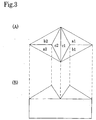
- the intermediate configuration of the elements having the rhombic bases as defined by said V-shaped grooves extending in two different directions is bilaterally asymmetrical as shown in Fig.2 attached to this specification, and at that intermediate stage the reflective lateral surfaces are a2 and b2 in said Fig.2.
- the intermediate shape in conventional art is formed by symmetrical V-shaped grooves as shown in Fig.1, and the reflective lateral surfaces formed are symmetrical, paired surfaces (a1, b1, and a2, b2).
- Fig.1 shows a pair of symmetrical triangular-pyramidal cube-corner element pair facing with each other as illustrated in Fig.3 when a pair of surfaces (a1, b1 and a2, b2) are cut off with the third V-shaped groove.
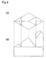
- cube-corner elements in Benson, et al.'s retroreflective article which are formed as plural V-shaped grooves are cut, do not form any pair, as illustrated in Fig.4.
- Fig.6 shows an example of the retroreflective element array as shown in Fig.30 of Benson, et al.'s US Patent 5,831,767.
- optical axes of any two reflective elements facing with each other across a V-shaped groove are alined in identical direction, as understood from their configuration.
- the optical axes are tilted, they are tilted in a same direction. Consequently, although a certain extent of improvement in observation angularity can be expected due to divergence of reflective light attributable to versatility of the reflective elements, in respect of entrance angularity the reflective element array has very high directivity. That is, in the direction to which their optical axes are tilted, excellent entrance angularity can be expected, but the array must have inferior entrance angularity in other directions.
- US Patent 5,889,615 to Dreyer, et al. shows retroreflective element pair having plural optical axes constituted of a pair of a triangular-pyramidal cube-corner element and a tent-type cube-corner element, which is formed of a pair of triangular-pyramidal cube-corner reflective elements having one base edge in common and confronting with each other, with their apices cut off with another V-shaped groove extending in parallel with said common base edge.
- Fig.5 attached to the present specification shows four sets of said retroreflective element pairs arranged in the closest-packed state.
- This retroreflective element of Dreyer, et al. has plural optical axes which turn to mutually different directions. Hence, light rays coming from the directions corresponding to those of optical axes of particular retroreflective elements are effectively reflected by the particular elements, but other elements show markedly decreased reflection efficiency, and as a whole the retroreflective article has to show inferior retroreflective characteristics.
- US Patent 4,775,219 to Appeldorn, et al. discloses a retroreflective article which carries on one surface an array of cube-corner retroreflective elements, the three lateral reflecting faces of the elements being formed by three intersecting sets of V-shaped grooves, at least one of the sets including, in a repeating pattern, at least two groove side angles that differ from one another, whereby the array of cube-corner retroreflective elements is divided into repeating sub-arrays that each comprise a plurality of cube-corner retroreflective elements in a plurality of distinctive shapes that retroreflect incident light in distinctively shaped light patterns.
- the retroreflective sheeting obtained according to the above proposal by Appeldorn, et al. shows improved observation angularity to a certain extent, but is insufficient as to improvement in entrance angularity.
- each cube corner array is formed by three intersecting sets of substantially parallel grooves including a primary groove set and two secondary groove sets, for at least one cube corner array, the secondary groove sets intersect each other to define an included angle less than 60°; and a major portion of substantially every groove in the primary groove set of the at least one cube corner array is disposed in a plane that intersects the edge of the sheeting at an acute angle selected from the group of angles consisting of 5 to 25°, 35 to 55°, and 65 to 85°.
- US Patent 5,812,315 discloses a retroreflective cube corner article formed from a substantially optically transparent material, comprising: a substrate having a base surface disposed in a base plane; a structured surface displaced from the base surface and including an array of canted cube corner element matched pairs formed by three mutually intersecting sets of substantially parallel grooves, each matched pair including a first cube corner element and an optically opposing second cube corner element, wherein: a plurality of cube corner elements in the array have their symmetry axes canted in a first plane through a cant angle measuring between 4° and 15°; the article exhibits its broadest range of entrance angularity in a second plane, angularly displaced from the first plane; and the cube corner elements are oriented such that the second plane intersects an edge of the article at an angle less than 15°.
- US Patents 5,822,121 and 5,926,314 disclose cube-corner articles wherein a plurality of cube corner elements in the array as above-described comprise a base triangle bounded by one groove from each of the three intersecting, groove sets, the base triangle being scalene.
- entrance angularity is markedly improved by a retroreflective device in which a large number of complex cube-corner retroreflective elements are arranged in closest-packed state, each of said complex cube-corner retroreflective elements having a first and second trianglar-pyramidal retroreflective units and at least one quadrilateral retroreflective unit, wherein the three reflective lateral faces (a1, b1, c1 and a2, b2, c2) of each of the first and second triangular-pyramidal retroreflective units form mutually perpendicular cube-corner reflective surfaces, respectively, the first reflective lateral face (f11), the second reflective lateral face (e11) and the third reflective lateral face (g11) of said at least one quadrilateral retroreflective unit form a mutually perpendicular cube-corner reflective surfaces, said first reflective lateral face (a1) of the first triangular-pyramidal retroreflective unit is on the same plane with the first
- Figs. 7 (A) and 7 (B) are a plan view and cross-sectional view for explaining a triangular-pyramidal cube-corner retroreflective element according to conventional technology, for comparison with a complex cube-corner retroreflective element of the present invention (which may be hereafter referred to simply as a complex reflective element) .
- Fig. 7 (A) shows triangular-pyramidal cube-corner retroreflective elements projecting on a common plane with their bases arranged in the closest-packed state on said common plane (S-S') as multiple element pairs each having one base line (x,x..) in common and facing with each other approximately symmetrically at equal height with respect to a plane (Lx-Lx') perpendicular to a common plane (S-S') including said common base lines (x,x(7) of said many elements.
- Fig. 7 (B) shows the cross-section of said pair of reflective elements among the triangular-pyramidal reflective element group shown in Fig. 7 (A).
- the element pair consists of canted triangular-pyramidal cube-corner retroreflective elements whose optical axes are tilted in the directions exactly opposite to each other, the optical axes tilting toward said perpendicular plane (Lx-Lx'), i.e., in such directions that the respective differences between the respective distances (P1, P2) from the points of intersection (P1, P2) of perpendicular lines drawn from apices (H1, H2) of the pair of elements toward the base plane (S-S') with said base plane (S-S') to the base line (x,x...) shared in common by said pair of elements, and the respective distances (q1, q2) from the points of intersection (Q1, Q2) of the optical axes with said base plane (S-S') to said base line (x,x%) shared in common by the element pair
- Figs. 9(A) and 9(B) show a plan view and cross-sectional view to explain one embodiment of retroreflective element device according to the present invention.
- Figs. 10(A) and 10(B) show one pair of the complex cube-corner retroreflective elements taken out from the device illustrated in Figs. 9(A) and 9(B).
- FIGS. 1-10 show a retroreflective device in which many complex cube-corner retroreflective elements, each comprising first and second triangular-pyramidal retroreflective units and at least two pairs of quadrilateral retroreflective units, are disposed in the closest-packed state, said device being characterized in that the three reflective lateral faces (a1, b1, c1 and a2, b2, c2) of each of the first and second triangular-pyramidal retroreflective units form mutually perpendicular cube-corner reflective surfaces, respectively, the first reflective lateral faces (f11, f12 and f21, f22), the second reflective lateral faces (e11, e12 and e21, e22) and the third reflective lateral faces (g11, g12 and g21, g22) of said two quadrilateral retroreflective units form mutually perpendicular cube-corner reflective surfaces, respectively, said first reflective lateral face (a1) of the first triangular-
- optical axes of each pair having substantially same tilt ( ⁇ ) in respect of the common base line (x) although differing in direction by 180° to each other, constitute the complex cube-corner retroreflective element.
- Figs. 9(B) and 10(B) show cross-sections of each pair of the complex cube-corner retroreflective elements as shown in Figs. 9(A) and 10(A).
- the pair of elements are tilted complex cube-corner retroreflective elements and optical axes of each element forming the pair (t11, t12, t13 and t21, t22, t23, respectively) are tilted in the exactly opposite directions.
- heights of the first and second triangular-pyramidal reflective units in the forms rotated by 180° to one another in respect of the common base line (x) is the same, as so are the heights of respectively matched quadrilateral retroreflective units.
- the complex cube-corner retroreflective elements used in the invention can contain plural optical axes (t11, t12, t13 and t21, t22, t23 in Fig. 10) in one pair, improvement can be achieved in the drawback arising particularly when tilt in optical axis is increased that the areal ratio of one of reflective lateral face (c1) of an element to the other reflective lateral faces (a1, b1) as shown in Fig. 7(A) becomes great and the element's reflective efficiency drops.
- the fourth V-shaped groove set (w-lines) can traverse, for example referring to Fig.
- Figs. 11 (A) and 11(B) illustrate another embodiment of complex cube-corner retroreflective element.
- Figs. 11(A) and 11(B) show a complex cube-corner retroreflective element having a pair of triangular-pyramidal retroreflective units and a pair of quadrilateral retroreflective units, characterized in that the three reflective lateral faces (a1, b1, c1 and a2, b2, c2) of each of the pair of triangular-pyramidal retroreflective units form mutually perpendicular cube-corner reflective surfaces, respectively, the first reflective lateral faces (f11, f21), the second reflective lateral faces (e11, e21) and the third reflective lateral faces (g11, g21) of said pair of quadrilateral retroreflective units form a mutually perpendicular cube-corner reflective surfaces, respectively, said first reflective lateral faces (a1, a2) of the pair of triangular-pyramidal retroreflective units are on the same plane with the first lateral faces (f11, f21) of said quadrilateral
- Fig. 11(B) shows a complex reflective element in which, where the distance from an apex (H) to Sx plane determined by the x-line group is expressed as hx; the distance to Sy plane defined by the y-line group, as hy; the distance to Sz plane defmed by the z-line group, as hz, and that to Sw plane defined by w-line group determined by base line of the fourth reflective lateral face of said quadrilateral retroreflective unit (d11 or d21), as hw, hx equals hw, hy equals hz, and the ratio of hx to hy is 1.05-1.5.
- the V-shaped grooves providing the base line (x) and base line (w) are formed deeper than the other grooves providing the base lines (y,z) so that hx equals hw, hy equals hz and the ratio of hx to hy is 1.05-1.5.
- areas of reflective lateral faces (g11, g21) and of reflective lateral faces (c1, c2) can be increased to achieve improvement in reflective efficiency.
- Such embodiments with deeper grooves are particularly effective, when the optical axes are tilted in such directions, where the point of intersection of a perpendicular line drawn from apex (H) of the quadrilateral retroreflective unit having one of its base lines on x-x' line with Sx plane as defined by x-x' line group is represented by P and the point of intersection of the optical axis of same quadrilateral retroreflective unit with said Sx plane is represented by Q, the difference (q-p) between the distance (q) from x-x' line to point Q and the distance (p) from x-x' line to point P takes a positive (+) value (positive tilting).
- V-shaped grooves formed by x-lines or w-lines it is preferred to deepen the V-shaped grooves formed by x-lines or w-lines to render hx greater than hy, so that the depth ratio, hx/hy, should fall within a range of 1.05-1.5, preferably 1.07-1.4.
- V-shaped grooves which are formed by x-lines and/or w-lines to make hx less than hy so that the depth ratio, hx/hy, in the elements with negatively tilted optical axes should fall within a range of 0.67-0.95, preferably 0.71-0.93.
- the beam is diverged with an intensity inversely proportional to the area of said aperture, due to diffractive effect.
- the divergence improves visibility of reflected light to an observer (vehicle driver) present at a distant place from the light source (head lamp) (improvement in observation angularity).
- the aperture through which a light beam passes signifies the faces surrounded by three reflective lateral faces (a1, b1, c1 or a2, b2, c2) of the shown triangular-pyramids, respectively, (bases of the elements, ABC1 and ABC2) whose area varies in proportion to height of the element.
- the aperture area decreases, and divergence of the reflected light enlarges due to increased diffraction effect.
- the element height is 50 ⁇ m or less, divergence of the reflected light rapidly increases.
- excessively small element dimensions results in excessive divergence of light and leads to decrease in retroreflection intensity in the front direction from which the light enters.
- the complex cube-corner retroreflective element according to the present invention includes plural optical axes differing in height, and the cube-corner units each having one optical axis have aperture area differing from one another. This enables to enlarge divergence of reflected light by increased diffractive effect, without excessively reducing the element height, which leads to improvement in observation angularity compared with known element pairs containing a pair of optical axes.
- the reflective element height (h) is less than 30 ⁇ m, the reflective element size becomes too small, and due to the diffraction effect which is decided by the aperture area of the reflective element, divergence of retroreflected light becomes excessive to reduce retroreflectivity. Whereas, any of the heights (h) of the element exceeding 400 ⁇ m is undesirable because it renders thickness of the sheeting too large to make a pliable sheeting.
- a cube-corner retroreflective sheeting having triangular-pyramidal reflective units in which the distance (hx) from the Sx plane determined by the x-line group of the many complex cube-corner retroreflective elements to the apex (H1, H2) of one of the complex cube-corner retroreflective element pair is 30-400 ⁇ m, in particular, 50-200 ⁇ m, inter alia, 60-120 ⁇ m, is preferred.
- Figs. 12(A) and 12(B) show a retroreflective device as described in any one of Claims 1-11, which is characterized in that the bottoms of at least one of those substantially symmetrical V-shaped parallel groove groups (Vx, Vy, Vz and Vw) which are defined by said x-, y-, z- and w-line groups forming the triangular-pyramidal retroreflective units or quadrilateral retroreflective units are formed of a flat surface or a curved quadratic surface.
- Vx, Vy, Vz and Vw substantially symmetrical V-shaped parallel groove groups
- the base of at least one of the substantially symmetrical V-shaped parallel groove groups (Vx and Vw) which are defined by the x and w line groups is formed of a flat surface, and the width of the flat portion of the V-shape is ⁇ .
- the shape of the head of V may be flat or a curved quadratic surface.
- the cross-sectional shape of the V-shaped groove (Vx) forming the reflective lateral faces which face each other (g11, g21) and/or the cross sectional shape of the fourth V-shaped groove group (Vw) which cut off the lateral faces (a1, b1) is substantially symmetrical trapezoid, the width ( ⁇ ) of the bottom of the grooves being preferably 3-20 ⁇ m.
- the optical axis is tilted to such an extent that the distance (q) between x-x' line and said point Q and the distance (p) between x-x' line and the point P are not equal.
- the reflective lateral faces (a1, a2) of the triangular-pyramidal retroreflective units are disposed on the same plane with the lateral faces (f11, f21) and the reflective lateral faces (c1, c2) are parallel to the faces (g11, g21) forming the V-shaped groove, respectively, tilt angles of the optical axes of the pair of triangular-pyramidal retroreflective elements are the same.
- the optical axes are tilted in the direction where the difference between the distance (q) from the x-x' line to the point Q and the distance (p) from the x-x' line to the point P, i.e., (q-p), takes a positive (+) value.
- the optical axes are tilted by 0.5-30°, preferably 5-20°, in the direction, where the point of intersection of a perpendicular line drawn from an apex (H) of one of the quadrilateral retroreflective units having one base line on x-x' line with the Sx plane determined by x-x' line group is made P, and the point of intersection of the optical axis of said quadrilateral retroreflective unit with said Sx plane is made Q, that the difference between the distance (q) from the x-x' line to the point Q and the distance (p) from the x-x' line to the point P, i.e., (q-p), takes a positive (+) value.
- Vx, Vy, Vz and Vw are determined by the x-, y-, z- and w-line groups of triangular-pyramidal retroreflective units or quadrilateral retroreflective unit(s)
- Vx, Vy, Vz and Vw are given a deviation
- the prismatic vertical angles of the triangular-pyramidal retroreflective units or of the quadrilateral retroreflective unit(s) which are formed by said V-shaped parallel grooves are given a deviation of ⁇ (0.001 - 0.1)° from 90°.
- V-shaped parallel groove groups (Vx, Vy, Vz and Vw) which are determined by the x-, y-, z- and w-line groups of the triangular-pyramidal retroreflective units or quadrilateral retroreflective unit(s), are given deviations such that the vertical angles of the cube-corner reflective elements formed by said group of V-shaped parallel grooves show deviations of ⁇ (0.001 - 0.1)° from 90°, in a pattern of repeating at least two different sets of deviations.
- angle of the V-shaped grooves in at least one direction is minutely and symmetrically deviated from the angle to give 90° to the prismatic vertical angle. This means to impart the deviation can be accomplished by using a bilaterally symmetrical cutting tool.
- the V-shaped grooves in at least one direction can be cut at an angle minutely and bilaterally asymmetrically deviated from the angle to give 90° to the prismatic vertical angles.
- This means to impart the deviation can be accomplished by using a bilaterally asymmetrical cutting tool or by slightly canting a bilaterally symmetrical cutting tool at the time of cutting.
- V-shaped parallel groove group (Vw) formed symmetrically in respect of w-lines
- the face which forms a right angle with the prismatic vertical angle is only one of the lateral faces or side walls of the V-shaped groove (referring to Fig. 10, g12, c1 and g22, c2). Therefore, the cross-sectional configuration of the V-shaped groove is not necessarily symmetrical, but the other side wall not contributing to retroreflection (d12, d11 and d21, d22) can have an optional angle.
- each adjacent complex reflective elements take bilaterally reversed configurations and cannot form cube-corner reflective faces. Therefore, the V-shaped grooves are preferably substantially symmetrical.
- retroreflective elements having deviated vertical angles are used, whereby retroreflected light does not return to the light source but retroreflect to a position slightly distant threfrom.
- the light can be effectively directed, for example, to a vehicle driver (observer) present at a distant position from the vehicle's head lamps, and the observation angularity is improved.
- the retroreflective elements are given various deviations in their vertical angles to advantageously provide a uniform observation angularity.
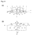
- Figs. 13(A) and 13(B) show a complex cube-corner retroreflective element comprising a pair of triangular-pyramidal retroreflective units and three quadrilateral retroreflective units whose bases are difined by base lines in four directions, in which said pair of triangular-pyramidal retroreflective units have different sizes and are disposed at spaced positions and the three reflective lateral faces (e, f, g) of each of the quadrilateral retroreflective units are mutually perpendicular to form cube corners where they meet, said quadrilateral units being disposed between the pair of triangular-pyramidal retroreflective units, two being at the right side and one, at the left side.
- Fig. 14 shows a plan view of a retroreflective device in which a large number of the complex cube-corner retroreflective elements as shown in Fig. 13 are disposed in the closest-packed state.
- Fig. 14 shows a repeated pattern of forming x line group and w line group, in which one w line is formed between two parallel x lines and between the next two parallel x lines, two w lines are formed.
- Fig. 15 shows a plan view of a retroreflective device in which the angle formed between the x lines of the device as illustrated above and an outer edge of a product formed of the retroreflective device is 5-85°, preferably 30-60°.
- Outer edge of the product as referred to herein signifies, where the product is a thin sheet-formed retroreflective sheeting, the longitudinal edge of a wound-up roll; or, where the product is an article like a thick-walled reflector, the edge in the horizontal direction may be the outer edge; or where the product has a circular shape, the standard edge may be the tangential line in the horizontal direction.
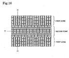
- Fig. 16 shows a plan view of an example of retroreflective device which has first zone(s) and second zone(s), the angle formed between any x1 line of the first zone and x2 line in the second zone ranging 5-175°, preferably 80-100°.
- the two zones are combined in such a manner that the angle formed by x 1 line of the first zone and the outer edge is 0° and the angle formed by x2 line of the second zone and the outer edge is 90°, which are disposed in repetitive pattern.
- Fig. 17 shows a plan view of an example of a retroreflective device in which a first zone and second zone are combined in repeated pattern, in such a manner that the angle [ ⁇ 1] of the first zone formed with the outer edge is 135°, and the angle [ ⁇ 2] of the second zone with the outer edge is 45°.
- Such a retroreflective device having first zone(s) and second zone(s), x1 line of the first zone and x2 line of the second zone form an angle of 5-175°, preferably 80-100°, can uniformize entrance angularity in horizontal and vertical directions and directions therebetween, by combining said zones.
- the retroreflective device may have three or more zones, in which x-lines of each zone are selected to form divided angles with the outer edge so that the angles become uniform in all directions.
- the most favorable retroreflective device is a retroreflective device in which many complex cube-corner retroreflective elements, each comprising first and second triangular-pyramidal retroreflective units and at least a pair of quadrilateral retroreflective units, are disposed in the closest-packed state, said device being characterized in that all the quadrilateral retroreflective units have an identical shape and mutually form rotation symmetrical pair as rotated by 180° to one another, said complex cube-corner retroreflective elements have rotation-symmetrical shapes, where the point of intersection of a perpendicular line drawn from the apex (H) of the quadrilateral retroreflective unit having one base line on x-x' line with Sx plane determined by x-x' line group is made P and the point of intersection of the optical axis of said quadrilateral retroreflective unit with said Sx plane is made Q, the optical axis is tilted by 5-20° in the direction such that the difference between
- those complex cube-corner retroreflective sheetings and retroreflective articles of the present invention can be manufactured with cube-corner-molding dies, e.g., a metallic belt on which reversed female pattern of complex cube-corner retroreflective elements are arranged in closest-packed state as described in the foregoing is inscribed.
- cube-corner-molding dies e.g., a metallic belt on which reversed female pattern of complex cube-corner retroreflective elements are arranged in closest-packed state as described in the foregoing is inscribed.
- V-shaped parallel groove groups in two directions (e.g., in the directions of y lines and z lines in Fig. 9 (A)), the groove groups having an identical depth (hy or hz) and substantially symmetrical cross-sectional shape, are cut, the repetition pitch in each direction, groove depth (e.g., h in Fig.
- V-shaped grooves having a same depth (hx) and substantially symmetrical cross-section are so cut in the third direction (x-direction) as to pass the intersections (A, B, C1, C2) of the previously formed V-shaped grooves in y-direction and z-direction, using a similar super-hard cutting tool having a point angle of about 30-110°.
- the fourth group of V-shaped grooves (w-direction) having a depth (hw) are cut in parallel with the V-shaped grooves in x-direction at such a repetition pitch as to divide each pitch between any two x grooves into an integral number of plural parts, with a super-hard cutting tool having a point angle similar to that of the tool used for cutting the V-shaped grooves in x-direction.
- depths of the grooves in x- and w-directions (hx, hw) may be the same with that of the grooves in y-and z-directions (hy or hz) or can be made deeper or shallower.
- the V-shaped grooves in x-direction are so cut as to make the distance (h) between the plane (Sx-Sx') inclusive of the many base lines (x,x,...) of the many complex cube-corner retroreflective elements projecting on the common base (Sx-Sx') and apices (H1, H2) of said complex cube-corner retroreflective element pair, 30-400 ⁇ m, in particular, 50-200 ⁇ m, inter alia , 60-120 ⁇ m.
- the depth of the V-shaped grooves in y-and z-directions may be same with that of the V-shaped grooves in x-direction, or may be made shallower to give the depth ratio hx/hy or hx/hz to fall within a range of 1.05-1.5, preferably 1.07-1.4.
- the depth of the V-shaped grooves in w-direction may be the same to, or different from, that of the grooves in x-direction.
- metallic materials having a Vickers hardness as defined by JIS Z 2244 of at least 350, in particular, at least 380, are preferred, specific examples including amorphous copper, electrodeposited nickel and aluminum; and as alloy materials, copper-zinc alloy (brass), copper-tin-zinc alloy, nickel-cobalt alloy, nickel-zinc alloy and aluminum alloy.
- synthetic resins can also be used, which preferably are those having a glass transition point of at least 150°C, in particular, at least 200°C, and a Rockwell hardness (JIS Z 2245) of at least 70, in particular, at least 75, to avoid such inconvenience that a resin softens during the cutting process to make high precision cutting difficult.
- useful resins include polyethylene tetraphthalate resins, polybutylene phthalate resins, polycarbonate resins, polymethyl methacrylate resins, polyimide resins, polyarylate resins, polyether sulfon resins, polyether imide resins and cellulose triacetate resins.
- microprismatic master mold is given an electroforming processing to form a metallic coating on its surface.
- a metallic die to be used for molding a complex cube-corner retroreflective sheeting or device of the present invention is provided.
- said electroforming is conducted, for example, in 60 wt% aqueous solution of nickel sulfamate, under such conditions as around 40°C and 10A/dm 2 electric current.
- the formation rate of electroformed layer for example, one not faster than about 0.02 mm/hr is suitable for providing a uniform electroformed layer.
- troubles such as lack in surface smoothness or formation of defective part in the electroformed layer are apt to be caused.
- the first generation electroformed die made from the prismatic master mold can be repetitively used as an electroformed master die for making second generation electroformed dies. Therefore, plural electroformed dies can be made from one prismatic master mold.
- the assembled electroformed die is used for molding synthetic resin, as a synthetic resin-molding die.
- synthetic resin as a synthetic resin-molding die.
- means for molding synthetic resin compression molding or injection molding can be adopted.
- Compression molding comprises, for example, inserting a thin-walled nickel electroformed die prepared as above, a synthetic resin sheet of a prescribed thickness and a silicone rubber sheet of approximately 5 mm in thickness as a cushioning material into a compression molding press which has been heated to a prescribed temperature; preheating the inserted materials under a pressure of 10-20% that of the prescribed molding pressure for 30 seconds; and heating and pressurizing said materials under such conditions as around 180-250°C ad 10-30 kg/cm 2 , for about 2 minutes. Thereafter the press is cooled to room temperature while maintaining the pressurized condition, and then the pressure is released to provide a prismatic molded product.
- the injection molding can be conducted using a thick-walled electroformed nickel die which was formed by the above-described method as an injection molding die according to accepted practice, and a customarily used injection molding machine.
- an injection molding method wherein a mobile die and fixed die are kept under pressure during pouring molten resin into the dies, or an injection compression method can be adopted wherein the mobile die and fixed die are not given a pressure and the molten resin is poured through a minor aperture opened and thereafter the system is pressurized.
- These methods are suitable particularly for making thick-walled products, e.g., a pavement marker.
- 0.5 mm-thick thin-walled electroformed dies made by the above method can be bonded by aforementioned welding method to form an endless belt die, which is mounted on a pair of a heating roll and a cooling roll and rotated.
- molten synthetic resin is supplied in sheet form, pressure molded with at least one silicone roll, cooled on the cooling roll to a temperature not higher than the glass transition point, and stripped off from the belt die.
- a continuous sheet-formed product can be obtained.
- the numeral 4 is a reflective element layer in which the complex cube-corner retroreflective elements (Rl, R2) of the present invention are disposed in closest packed state; 3 is a holder layer which holds the reflective elements; and the arrow 11 shows the direction of incident light.
- the reflective element layer (4) and the holder layer (3) form an integral body (5), but they may be a laminate of two different layers.
- a surface protective layer (1), print layer (2) to convey information to a viewer or to impart color to the sheeting, binder layer (7) to provide an airtightly sealed structure to prevent infiltration of water to the back of the reflective element layer, support layer (8) to support the binder layer (7); and an adhesive layer (9) with a peeling layer (10) for adhering the retroreflective sheeting or the retroreflective article to another structure can be provided.
- the print layer (2) can be installed normally between the surface protective layer (1) and the holder layer (3) or on the surface protective layer (1) or the reflection surface of the reflective element layer (4) by such ordinary means as gravure, screen printing, or ink-jet printing.
- the material for making said reflective element layer (4) and holder layer (3) is not critical so long as it satisfies pliability which is one of the objects to be achieved by the present invention, one having optical transparency and homogeneity is preferred.
- the material useful for the invention include polycarbonate resin, vinyl chloride resin, (meth)acrylic resin, epoxy resin, polystyrene resin, polyester resin, fluorine-contained resin, polyolefin resin such as polyethylene resin or polypropylene resin, cellulose resin, and polyurethane resin.
- ultraviolet absorber, photostabilizer, antioxidant and the like can be used either singly or in combination. Any of various organic pigments, inorganic pigments, fluorescent pigments, dyes, fluorescent dyes as colorlant may also be contained.
- the same resin as used for the retroreflective element layer (4) can be used, which may be incorporated with ultraviolet absorber, photostabilizer, antioxidant and the like which can be used either singly or in combination. Still in addition, various organic pigments, inorganic pigments, fluorescent pigments, dyes, fluorescent dyes and the like as colorlant may be incorporated.
- the reflective element layer (4) of the present invention It is a general practice with the reflective element layer (4) of the present invention, to provide an air layer (6) behind the complex cube-corner retroreflective elements, for enlarging the critical angle satisfying the total internal reflection conditions. To prevent such troubles under conditions of use as decrease in critical angle, corrosion of metallic layer or the like due to infiltrated moisture, the reflective element layer (4) and the support layer (8) are airtightly sealed by a binder layer (7).
- thermofusing resin binding method thermosetting resin binding method, ultraviolet curable resin binding method, electron beam curable resin binding method and the like can be suitably adopted.
- the binder layer (7) used in the present invention may be applied over the entire surface of the support layer (8), or can be selectively provided at the bonding portion(s) with the retroreflective element layer, by such means as printing method.
- Examples of the material for constituting the support layer (8) include resins for making the retroreflective element layer, film-forming resins in general, fibers, fabric, metallic foil or plate such as of stainless steel or aluminum, which can be used either singly or in combination.
- the adhesive layer (9) used for adhering the retroreflective sheeting or retroreflective article of the present invention onto metallic plate, wood board, glass sheet, plastic sheet and the like, and the peeling layer (10) for the adhesive can be suitably selected from known materials.
- the adhesive can be suitably selected among pressure-sensitive adhesives, heat-sensitive adhesives, crosslinkable adhesives and the like.
- pressure-sensitive adhesive include polyacrylate agglutinants obtained by copolymerizing acrylic acid esters such as butyl acrylate, 2-ethylhexyl acrylate, isooctyl acrylate, nonyl acrylate and the like, with acrylic acid, vinyl acetate and the like; silicone resin agglutinants; and rubber agglutinants.
- heat-sensitive adhesives acrylic, polyester or epoxy resins can be used.
- Fig. 19 is a cross-sectional view of the embodiment.
- a metallic specular reflective layer (12) is provided on the surfaces of the elements in the reflective element layer (4), and an adhesive layer and a peeling layer are laminated on, and in direct contact with, the specular reflection layer (12).
- the cube-corner retroreflective sheeting or retroreflective article of this embodiment do not require an air layer because they retroreflect on principle of specular reflection, and hence do not require any binder layer or support layer.
- the metallic specular reflection layer (12) installed on the element surfaces in the reflective element layer (4) of the present invention may cover the entire region of the element surfaces or cover it only partially.
- the specular reflection layer (12) formed of a metal such as aluminum, copper, silver, nickel or the like can be provided on the elements in the reflective element layer (4) of the complex cube-corner retroreflective sheeting or retroreflective device of the present invention by such means as vacuum vapor deposition, chemical plating or sputtering.
- vapor deposition means using aluminum is preferred, because the vapor deposition temperature can be lowered to minimize thermal deformation of the retroreflective elements during the vapor deposition step, and also the resulting specular reflective layer (12) shows the fairest color tone.
- An apparatus suitable for continuous vapor deposition of aluminum specular reflection layer (12) comprises a vacuum vessel which is capable of maintaining a degree of vacuum at around 7 to 9x 10 -4 mm Hg, said vacuum vessel accommodating therein a feeder for feeding an original prism sheeting formed of a base sheet and a surface protective layer which is laminated on the light entrance side surface of said base sheet; a take-up winder for winding up the original prism sheeting which has been vacuum-deposition treated; and a heating system installed therebetween which is capable of fusing the aluminum in a graphite crucible with an electric heater.
- a specular reflection layer (12) can be deposited on the surfaces of retroreflective elements at a thickness of, for example, 800-2000 ⁇ .
- a large number of parallel V-formed groove groups of symmetrical cross-sections were cut in y-direction and z-direction in a repetitive pattern by fly cutting method, on a 100 mm square brass plate with a flatly ground surface, with a diamond-tipped cutting tool having a point angle of 83.11°.
- the repetition pitch of V-shaped grooves in y-direction and z-direction was 201.45 ⁇ m
- the groove depth was 100.00 ⁇ m
- crossing angle of the V-shaped grooves in y-direction with those in z-direction was 38.207°.
- An intermediate configuration as shown in Fig. 1 was formed.
- V-shaped grooves were cut in the x-direction in repetitive pattern with a diamond-tipped cutting tool having a symmetrical cross-section and point angle of 40.53°, at a repetition pitch of said V-shaped grooves of 307.77 ⁇ m and to the V-shaped groove depth of 100.00 ⁇ m, each of said grooves passing through two points of intersection of the y-directioned grooves and z-directioned grooves, to form on said brass plate many male triangular-pyramidal cube-corner elements arranged in closest-packed state, each element taking an intermediate configuration as illustrated in Fig. 3.
- the height (h) from the apex (H11 or H21) to the base plane (S-S') was 100 ⁇ m.
- the tilt angle ( ⁇ ) of each optical axis of this complex cube-corner retroreflective element was +15°, and the vertical angles of the three lateral faces constituting the reflective element were invariably 90°.
- a female cube-corner forming die with reversed configuration made of nickel was prepared by electroforming method using a nickel sulfamate solution of 55% in concentration. Compression molding a 200 ⁇ m-thick polycarbonate resin sheet (Iupilon TMH3000, Mitsubishi Engineering Plastics K.K.) using this molding die, under the conditions of molding temperature of 200°C and molding pressure of 50 kg/cm 2 , the resin sheet was cooled to 30°C under the elevated pressure and withdrawn. Thus a retroreflective device with about 150 ° ⁇ m-thick holder layer (3) on whose surface a large number of polycarbonate resin complex cube-corner retroreflective elements of the element layer (4) were disposed in closest packed state was prepared.
- a polycarbonate resin retroreflective device in which a large number of the complex cube-corner retroreflective elements as illustrated in Figs. 11 (A) and 11 (B) were disposed in closest-packed state was prepared by the same method as described in Example 1, except that the depth of V-shaped grooves in x- and w-directions was made 115.00 ⁇ m.
- a polycarbonate resin retroreflective device in which a large number of the complex cube-corner retroreflective elements as illustrated in Fig. 12 (A) and 12 (B) were disposed in closest-packed state was prepared by the same method as described in Example 1, except that the point of the diamond-tipped tool used for cutting V-shaped grooves of x- and w-directions was advancedly lapped to have a width (dw) of 8 ⁇ m.
- V-shaped grooves in x- and w-directions were cut in a repetitive pattern of A-B-C, to form a master mold in which a large number of complex cube-corner retroreflective elements with varied deviations given to their vertical angles were disposed in closest-packed state.
- a polycarbonate resin retroreflective device in which a large number of complex cube-corner retroreflective elements were disposed in closest-packed state was prepared by the method as described in Example 1.
- a polycarbonate resin retroreflective device which was given an azimuth so that the x-line of said retroreflective device each formed an angle of 45° with the outer edge thereof, using the polycarbonate resin complex cube-corner retroreflective device as prepared in Example 2.
- An article formed of plural polycarbonate resin complex cube-corner retroreflective devices was prepared using the polycarbonate complex cube-corner retroreflective devices as prepared in Example 2. Said devices were repeatedly joined in such an arrangement that the first zone device in which its x-lines each formed an angle of 45 ° with the outer edge of the final product and the second zone device in which its x-lines each formed an angle of 135° with the outer edge of the final product appeared alternatively to form a 10-mm wide striped pattern.
- a polycarbonate resin retroreflective device in which a large number of complex cube-corner retroreflective elements as illustrated in Fig. 3 were disposed in closest-packed state was prepared by the same method as in Example 1, except that V-shaped grooves in x-, y- and z-directions were cut but V-shaped grooves in w-direction were not cut.
- the observation angularity (observation angle 1.0°) of the retroreflective device (retroreflective sheeting) in which a large number of the complex cube-corner retroreflective elements were arranged in the closest-packed state, which was prepared from the master mold in which a large number of complex cube-corner retroreflective elements with vertical angles deviated in various manner as described in Example 4 were arranged in closest-packed state, excelled over observation angularity of other retroreflective devices which were not given such vertical angle deviations.
- Example 1 Example 2
- Example 3 Example 4
- Example 5 Example 6 Comparative Example 0.2° 5° 780 797 631 562 720 704 493 10° 700 747 574 497 704 689 470 20° 400 550 374 306 545 544 280 30° 300 362 287 211 420 430 207 40° 250 270 216 199 345 350 192 50° 150 169 135 118 321 329 104 1.0° 5° 45 43 43 89 39 44 37
Landscapes
- Physics & Mathematics (AREA)
- General Physics & Mathematics (AREA)
- Optics & Photonics (AREA)
- Optical Elements Other Than Lenses (AREA)
- Window Of Vehicle (AREA)
- Molds, Cores, And Manufacturing Methods Thereof (AREA)
- Transition And Organic Metals Composition Catalysts For Addition Polymerization (AREA)
- Road Signs Or Road Markings (AREA)
- Aerials With Secondary Devices (AREA)
- Ultra Sonic Daignosis Equipment (AREA)
- Illuminated Signs And Luminous Advertising (AREA)
Applications Claiming Priority (3)
| Application Number | Priority Date | Filing Date | Title |
|---|---|---|---|
| JP2001241964 | 2001-08-09 | ||
| JP2001241964 | 2001-08-09 | ||
| PCT/JP2002/008187 WO2003014779A1 (fr) | 2001-08-09 | 2002-08-09 | Dispositif de retroreflexion |
Publications (3)
| Publication Number | Publication Date |
|---|---|
| EP1424572A1 EP1424572A1 (en) | 2004-06-02 |
| EP1424572A4 EP1424572A4 (en) | 2004-10-20 |
| EP1424572B1 true EP1424572B1 (en) | 2006-10-04 |
Family
ID=19072317
Family Applications (1)
| Application Number | Title | Priority Date | Filing Date |
|---|---|---|---|
| EP02762768A Expired - Lifetime EP1424572B1 (en) | 2001-08-09 | 2002-08-09 | Retroreflection device |
Country Status (12)
| Country | Link |
|---|---|
| US (1) | US6883921B2 (zh) |
| EP (1) | EP1424572B1 (zh) |
| JP (1) | JP4225897B2 (zh) |
| KR (1) | KR100901679B1 (zh) |
| CN (1) | CN100476463C (zh) |
| AT (1) | ATE341770T1 (zh) |
| AU (1) | AU2002328605B2 (zh) |
| BR (1) | BR0211774A (zh) |
| CA (1) | CA2456611C (zh) |
| DE (1) | DE60215200T2 (zh) |
| ES (1) | ES2268075T3 (zh) |
| WO (1) | WO2003014779A1 (zh) |
Cited By (1)
| Publication number | Priority date | Publication date | Assignee | Title |
|---|---|---|---|---|
| US11351745B2 (en) | 2020-08-27 | 2022-06-07 | Aura Optical Systems, Lp | Microprismatic retroreflective mold, sheet, and article and methods of manufacture thereof |
Families Citing this family (36)
| Publication number | Priority date | Publication date | Assignee | Title |
|---|---|---|---|---|
| US7584564B2 (en) * | 2002-07-08 | 2009-09-08 | Nippon Carbide Kogyo Kabushiki Kaisha | Internally illuminated sign |
| JP4727423B2 (ja) * | 2003-12-02 | 2011-07-20 | 日本カーバイド工業株式会社 | 湾曲した反射側面を持つ三角錐型キューブコーナー再帰反射物品 |
| US7179406B1 (en) * | 2004-03-08 | 2007-02-20 | Attar Adil H | Method and apparatus for making reflective pavement marker |
| WO2006067573A1 (en) * | 2004-12-22 | 2006-06-29 | Giorgio Corradi | A process for obtaining a back-reflecting multi-layer film, with a microprism support and a film obtained using the process |
| US7938549B2 (en) | 2005-11-30 | 2011-05-10 | Nippon Carbide Industries Co., Inc. | Retroreflective article |
| US7674028B2 (en) * | 2006-01-13 | 2010-03-09 | Avery Dennison Corporation | Light enhancing structures with multiple arrays of elongate features of varying characteristics |
| US7366393B2 (en) * | 2006-01-13 | 2008-04-29 | Optical Research Associates | Light enhancing structures with three or more arrays of elongate features |
| US20070086207A1 (en) * | 2006-01-13 | 2007-04-19 | Optical Research Associates | Display systems including light enhancing structures with arrays of elongate features |
| US7866871B2 (en) * | 2006-01-13 | 2011-01-11 | Avery Dennison Corporation | Light enhancing structures with a plurality of arrays of elongate features |
| US7545569B2 (en) | 2006-01-13 | 2009-06-09 | Avery Dennison Corporation | Optical apparatus with flipped compound prism structures |
| EP2023167B1 (en) * | 2006-06-06 | 2013-11-27 | Nippon Carbide Kogyo Kabushiki Kaisha | Cube corner type retroreflection article |
| US7482969B2 (en) * | 2006-06-14 | 2009-01-27 | Board Of Trustees Of The University Of Illinois | Material movement sensing techniques |
| GB0626055D0 (en) * | 2006-12-29 | 2007-11-07 | Bae Systems Plc | Detection of ionising radiation |
| US8224189B1 (en) * | 2007-02-02 | 2012-07-17 | Sunlight Photonics Inc. | Retro-directive target for free-space optical communication and method of producing the same |
| WO2009042118A1 (en) * | 2007-09-24 | 2009-04-02 | Reflexite Corporation | Retroreflective structure with fabric face |
| JP5091718B2 (ja) * | 2008-02-22 | 2012-12-05 | 日本カーバイド工業株式会社 | 再帰反射物品 |
| US8662682B2 (en) * | 2008-11-04 | 2014-03-04 | Susanna Sidoti Gorodisher | Magnetically repositionable reflective safety devices |
| DE102010042142B4 (de) * | 2009-10-09 | 2014-01-16 | Ifm Electronic Gmbh | Messgerät zur Erfassung der Drehbewegung einer Welle |
| CA2815786C (en) * | 2010-10-29 | 2015-07-07 | Nippon Carbide Industries Co., Inc. | Cube-corner retroreflective sheeting |
| GB2489955A (en) * | 2011-04-12 | 2012-10-17 | 3M Innovative Properties Co | Retroreflective sheeting |
| JP2012242509A (ja) * | 2011-05-17 | 2012-12-10 | Nikon Corp | 再帰反射部材、再帰反射性建材および建築物の建築方法 |
| JP2016513031A (ja) * | 2013-02-11 | 2016-05-12 | オラフォル アメリカズ インコーポレイテッド | キューブコーナー反射体およびその方法 |
| CN104133260B (zh) * | 2014-08-08 | 2016-09-14 | 浙江道明光电科技有限公司 | 一种新型的微棱镜型反光材料模具的制作方法 |
| JP6425069B2 (ja) * | 2014-10-17 | 2018-11-21 | ヤマトミシン製造株式会社 | ミシン |
| JP6405462B2 (ja) | 2015-06-12 | 2018-10-17 | 日本カーバイド工業株式会社 | 画像表示装置 |
| JP2017116779A (ja) * | 2015-12-25 | 2017-06-29 | スリーエム イノベイティブ プロパティズ カンパニー | 再帰性反射ライセンスプレート、及び再帰性反射シート |
| JP6833316B2 (ja) * | 2015-12-25 | 2021-02-24 | 株式会社アスカネット | 再帰性反射体及びその製造方法 |
| WO2018088074A1 (ja) * | 2016-11-14 | 2018-05-17 | 日本カーバイド工業株式会社 | 再帰反射シート |
| JP2018084794A (ja) * | 2016-11-14 | 2018-05-31 | 日本カーバイド工業株式会社 | 再帰反射シート |
| JP2018084793A (ja) * | 2016-11-14 | 2018-05-31 | 日本カーバイド工業株式会社 | 再帰反射シート |
| WO2018088073A1 (ja) * | 2016-11-14 | 2018-05-17 | 日本カーバイド工業株式会社 | 再帰反射シート |
| TWI756466B (zh) | 2017-08-29 | 2022-03-01 | 美商艾維利 丹尼森公司 | 用於基於投影機的顯示系統的回射片 |
| US11001979B2 (en) | 2018-08-13 | 2021-05-11 | Vergence Automation, Inc. | Methods and apparatus for ultrawide entrance angle reflective articles for use with autonomous vehicle machine vision systems |
| US11762133B1 (en) | 2018-09-13 | 2023-09-19 | Vergence Automation, Inc. | Retroreflective materials and articles incorporating near-ideal total internal retroreflective elements |
| EP3771931A1 (en) * | 2019-08-02 | 2021-02-03 | Reflomax Co., Ltd. | Cube corner type retroreflective sheet and manufacturing method thereof |
| US11124932B1 (en) * | 2021-04-30 | 2021-09-21 | Mark Joseph O'Neill | Retroreflective traffic stripe for both dry and wet weather conditions |
Family Cites Families (47)
| Publication number | Priority date | Publication date | Assignee | Title |
|---|---|---|---|---|
| US2380447A (en) * | 1945-07-31 | Optical reflecting material | ||
| US2310790A (en) * | 1943-02-09 | Optical reflecting material | ||
| GB441319A (en) | 1933-12-21 | 1936-01-16 | Gustave Leray | Improvements in or relating to light reflectors |
| US2481757A (en) * | 1945-05-23 | 1949-09-13 | Thoger G Jungersen | Optical reflecting material |
| US3190178A (en) * | 1961-06-29 | 1965-06-22 | Minnesota Mining & Mfg | Reflex-reflecting sheeting |
| US3712706A (en) * | 1971-01-04 | 1973-01-23 | American Cyanamid Co | Retroreflective surface |
| US3830682A (en) * | 1972-11-06 | 1974-08-20 | Rowland Dev Corp | Retroreflecting signs and the like with novel day-night coloration |
| USRE29396E (en) * | 1975-02-18 | 1977-09-13 | Amerace Corporation | Pin having nonaligned cube axis and pin axis and bundle of such pins |
| US4025159A (en) * | 1976-02-17 | 1977-05-24 | Minnesota Mining And Manufacturing Company | Cellular retroreflective sheeting |
| US4349598A (en) * | 1976-12-01 | 1982-09-14 | Minnesota Mining And Manufacturing Company | High incidence angle retroreflective material |
| US4498733A (en) * | 1982-07-02 | 1985-02-12 | Amerace Corporation | Reflector structure |
| AU560276B2 (en) | 1983-09-12 | 1987-04-02 | Minnesota Mining And Manufacturing Company | Cube-corner retroreflective articles |
| US4588258A (en) * | 1983-09-12 | 1986-05-13 | Minnesota Mining And Manufacturing Company | Cube-corner retroreflective articles having wide angularity in multiple viewing planes |
| MX169129B (es) | 1984-08-10 | 1993-06-22 | Amerace Corp | Metodo para producir construcciones de lamina de estructura laminada retrorreflejante del tipo de esquinas de cubo y el producto obtenido con el mismo. |
| US5064272A (en) * | 1985-11-18 | 1991-11-12 | Minnesota Mining And Manufacturing Company | Encapsulated-lens retroreflective sheeting and method of making |
| US4897136A (en) * | 1985-11-18 | 1990-01-30 | Minnesota Mining And Manufacturing Company | Method of making encapsulated-lens retroreflective sheeting |
| US4775219A (en) | 1986-11-21 | 1988-10-04 | Minnesota Mining & Manufacturing Company | Cube-corner retroreflective articles having tailored divergence profiles |
| US4801193A (en) * | 1988-03-04 | 1989-01-31 | Reflexite Corporation | Retroreflective sheet material and method of making same |
| US5264063A (en) * | 1990-05-16 | 1993-11-23 | Reflexite Corporation | Method for making flexible retroreflective sheet material |
| US5138488A (en) | 1990-09-10 | 1992-08-11 | Minnesota Mining And Manufacturing Company | Retroreflective material with improved angularity |
| DE4242264C2 (de) | 1992-12-15 | 1994-09-22 | Gubela Sen Hans Erich | Körper oder Bauteil mit einer Mikrodoppeltripel aufweisenden Oberfläche sowie Verfahren zur Herstellung eines derartigen Körpers oder Bauteils |
| US5376431A (en) * | 1993-05-12 | 1994-12-27 | Reflexite Corporation | Retroreflective microprism sheeting with silver/copper reflecting coating and method of making same |
| DE69428450T2 (de) * | 1993-10-20 | 2002-05-16 | Minnesota Mining And Mfg. Co., Saint Paul | Vielfach strukturierter würfelecken-körper |
| US5600484A (en) * | 1993-10-20 | 1997-02-04 | Minnesota Mining And Manufacturing Company | Machining techniques for retroreflective cube corner article and method of manufacture |
| US5450235A (en) * | 1993-10-20 | 1995-09-12 | Minnesota Mining And Manufacturing Company | Flexible cube-corner retroreflective sheeting |
| EP0724735B1 (en) * | 1993-10-20 | 2002-02-20 | Minnesota Mining And Manufacturing Company | Directly machined raised structure retroreflective cube corner article and method of manufacture |
| JP3834596B2 (ja) | 1993-10-20 | 2006-10-18 | スリーエム カンパニー | 非対称性コーナキューブ物品と製作方法 |
| US6206525B1 (en) * | 1994-09-28 | 2001-03-27 | Reflexite Corporation | Miniature micro prism retroreflector |
| DE69509670T2 (de) | 1994-09-28 | 1999-11-18 | Reflexite Corp., Avon | Retroreflektive geneigte prismenstruktur |
| US5565151A (en) * | 1994-09-28 | 1996-10-15 | Reflexite Corporation | Retroreflective prism structure with windows formed thereon |
| WO1996042025A1 (en) * | 1995-06-09 | 1996-12-27 | Minnesota Mining And Manufacturing Company | Cube corner articles exhibiting improved entrance angularity in one or more planes |
| US5706132A (en) * | 1996-01-19 | 1998-01-06 | Minnesota Mining And Manufacturing Company | Dual orientation retroreflective sheeting |
| CA2169807C (en) * | 1996-02-19 | 1999-09-07 | Italo Caroli | Reflex pin with adjusted angle |
| US5840405A (en) * | 1996-04-30 | 1998-11-24 | Minnesota Mining And Manufacturing Company | Glittering cube-corner retroreflective sheeting |
| US5814355A (en) * | 1996-04-30 | 1998-09-29 | Minnesota Mining And Manufacturing Company | Mold for producing glittering cube-corner retroreflective sheeting |
| EP0887665B1 (en) * | 1996-10-18 | 2004-12-22 | Nippon Carbide Kogyo Kabushiki Kaisha | Triangular pyramidal cube corner type retroreflective sheet |
| US5854709A (en) * | 1997-06-24 | 1998-12-29 | Stimsonite Corporation | Chameleonic cube corners |
| US5889615A (en) * | 1997-06-27 | 1999-03-30 | Minnesota Mining And Manufacturing Company | Dual axis retroreflective articles |
| US5898523A (en) * | 1997-07-02 | 1999-04-27 | Minnesota Mining & Manufacturing Company | Tiled retroreflective sheeting composed of highly canted cube corner elements |
| US5981032A (en) * | 1997-07-02 | 1999-11-09 | 3M Innovative Properties Company | Retroreflective cube corner sheeting mold and sheeting formed therefrom |
| JP3580999B2 (ja) | 1997-11-17 | 2004-10-27 | 日本カーバイド工業株式会社 | 三角錐型キューブコーナー再帰反射シート |
| US6036322A (en) * | 1997-12-01 | 2000-03-14 | Reflexite Corporation | Multi-orientation retroreflective structure |
| EP1040374B1 (en) * | 1997-12-16 | 2004-05-06 | Reflexite Corporation | Perforated retroreflective film |
| JP3975001B2 (ja) * | 1998-04-22 | 2007-09-12 | 日本カーバイド工業株式会社 | 三角錐型キユーブコーナー再帰反射シート |
| JP4225602B2 (ja) | 1998-04-22 | 2009-02-18 | 日本カーバイド工業株式会社 | 三角錐型キユーブコーナー再帰反射シート |
| JP3975039B2 (ja) * | 1999-12-13 | 2007-09-12 | 日本カーバイド工業株式会社 | 三角錐型キューブコーナー再帰反射素子 |
| JP3468418B2 (ja) * | 2000-03-15 | 2003-11-17 | 日本カーバイド工業株式会社 | 三角錐型キユーブコーナー型再帰反射シート |
-
2002
- 2002-08-09 ES ES02762768T patent/ES2268075T3/es not_active Expired - Lifetime
- 2002-08-09 DE DE60215200T patent/DE60215200T2/de not_active Expired - Lifetime
- 2002-08-09 AT AT02762768T patent/ATE341770T1/de not_active IP Right Cessation
- 2002-08-09 AU AU2002328605A patent/AU2002328605B2/en not_active Ceased
- 2002-08-09 BR BR0211774-6A patent/BR0211774A/pt not_active IP Right Cessation
- 2002-08-09 EP EP02762768A patent/EP1424572B1/en not_active Expired - Lifetime
- 2002-08-09 CN CNB028155262A patent/CN100476463C/zh not_active Expired - Fee Related
- 2002-08-09 JP JP2003519656A patent/JP4225897B2/ja not_active Expired - Fee Related
- 2002-08-09 KR KR1020037017218A patent/KR100901679B1/ko not_active IP Right Cessation
- 2002-08-09 US US10/486,576 patent/US6883921B2/en not_active Expired - Fee Related
- 2002-08-09 WO PCT/JP2002/008187 patent/WO2003014779A1/ja active IP Right Grant
- 2002-08-09 CA CA2456611A patent/CA2456611C/en not_active Expired - Fee Related
Cited By (3)
| Publication number | Priority date | Publication date | Assignee | Title |
|---|---|---|---|---|
| US11351745B2 (en) | 2020-08-27 | 2022-06-07 | Aura Optical Systems, Lp | Microprismatic retroreflective mold, sheet, and article and methods of manufacture thereof |
| US11691365B2 (en) | 2020-08-27 | 2023-07-04 | Aura Optical Systems, Lp | Microprismatic retroreflective mold, sheet, and article and methods of manufacture thereof |
| US12059858B2 (en) | 2020-08-27 | 2024-08-13 | Aura Optical Systems, Lp | Microprismatic retroreflective mold, sheet, and article and methods of manufacture thereof |
Also Published As
| Publication number | Publication date |
|---|---|
| ES2268075T3 (es) | 2007-03-16 |
| KR20040020952A (ko) | 2004-03-09 |
| EP1424572A4 (en) | 2004-10-20 |
| EP1424572A1 (en) | 2004-06-02 |
| ATE341770T1 (de) | 2006-10-15 |
| CN100476463C (zh) | 2009-04-08 |
| US6883921B2 (en) | 2005-04-26 |
| DE60215200T2 (de) | 2007-08-23 |
| KR100901679B1 (ko) | 2009-06-08 |
| JPWO2003014779A1 (ja) | 2004-11-25 |
| WO2003014779A1 (fr) | 2003-02-20 |
| JP4225897B2 (ja) | 2009-02-18 |
| US20050018292A1 (en) | 2005-01-27 |
| BR0211774A (pt) | 2004-07-27 |
| AU2002328605B2 (en) | 2007-04-05 |
| CN1539086A (zh) | 2004-10-20 |
| CA2456611C (en) | 2010-09-21 |
| CA2456611A1 (en) | 2003-02-20 |
| DE60215200D1 (de) | 2006-11-16 |
| WO2003014779A9 (en) | 2004-10-07 |
Similar Documents
| Publication | Publication Date | Title |
|---|---|---|
| EP1424572B1 (en) | Retroreflection device | |
| CA2340599C (en) | Triangular-pyramidal cube-corner retroreflective sheeting | |
| JP5331088B2 (ja) | 湾曲した反射側面を持つ三角錐型キューブコーナー再帰反射物品 | |
| US6083607A (en) | Triangular pyramidal cube corner type retroreflective sheet | |
| JP3931256B2 (ja) | 1つ以上の面において改善された照射角を形成するキューブコーナ製品 | |
| US5898523A (en) | Tiled retroreflective sheeting composed of highly canted cube corner elements | |
| CA2329705C (en) | Triangular-pyramidal cube-corner retroreflective sheeting | |
| CA2363723C (en) | Triangular-pyramidal cube-corner retroreflective sheeting | |
| JP4225602B2 (ja) | 三角錐型キユーブコーナー再帰反射シート | |
| EP1271189A1 (en) | Triangular pyramidal cube corner retroreflection element | |
| JP3824471B2 (ja) | キューブコーナー型再帰反射シート及びキューブコーナー金型 | |
| JP2005049385A (ja) | 副反射側面が設置された三角錐型キューブコーナー再帰反射物品 | |
| JP2001021708A (ja) | 再帰反射シート | |
| JP2954709B2 (ja) | 三角錐型キューブコーナー型再帰反射シート |
Legal Events
| Date | Code | Title | Description |
|---|---|---|---|
| PUAI | Public reference made under article 153(3) epc to a published international application that has entered the european phase |
Free format text: ORIGINAL CODE: 0009012 |
|
| 17P | Request for examination filed |
Effective date: 20040227 |
|
| AK | Designated contracting states |
Kind code of ref document: A1 Designated state(s): AT BE BG CH CY CZ DE DK EE ES FI FR GB GR IE IT LI LU MC NL PT SE SK TR |
|
| AX | Request for extension of the european patent |
Extension state: AL LT LV MK RO SI |
|
| A4 | Supplementary search report drawn up and despatched |
Effective date: 20040907 |
|
| 17Q | First examination report despatched |
Effective date: 20041129 |
|
| GRAP | Despatch of communication of intention to grant a patent |
Free format text: ORIGINAL CODE: EPIDOSNIGR1 |
|
| GRAS | Grant fee paid |
Free format text: ORIGINAL CODE: EPIDOSNIGR3 |
|
| GRAA | (expected) grant |
Free format text: ORIGINAL CODE: 0009210 |
|
| AK | Designated contracting states |
Kind code of ref document: B1 Designated state(s): AT BE BG CH CY CZ DE DK EE ES FI FR GB GR IE IT LI LU MC NL PT SE SK TR |
|
| PG25 | Lapsed in a contracting state [announced via postgrant information from national office to epo] |
Ref country code: BE Free format text: LAPSE BECAUSE OF FAILURE TO SUBMIT A TRANSLATION OF THE DESCRIPTION OR TO PAY THE FEE WITHIN THE PRESCRIBED TIME-LIMIT Effective date: 20061004 Ref country code: IT Free format text: LAPSE BECAUSE OF FAILURE TO SUBMIT A TRANSLATION OF THE DESCRIPTION OR TO PAY THE FEE WITHIN THE PRESCRIBED TIME-LIMIT;WARNING: LAPSES OF ITALIAN PATENTS WITH EFFECTIVE DATE BEFORE 2007 MAY HAVE OCCURRED AT ANY TIME BEFORE 2007. THE CORRECT EFFECTIVE DATE MAY BE DIFFERENT FROM THE ONE RECORDED. Effective date: 20061004 Ref country code: CZ Free format text: LAPSE BECAUSE OF FAILURE TO SUBMIT A TRANSLATION OF THE DESCRIPTION OR TO PAY THE FEE WITHIN THE PRESCRIBED TIME-LIMIT Effective date: 20061004 Ref country code: LI Free format text: LAPSE BECAUSE OF FAILURE TO SUBMIT A TRANSLATION OF THE DESCRIPTION OR TO PAY THE FEE WITHIN THE PRESCRIBED TIME-LIMIT Effective date: 20061004 Ref country code: NL Free format text: LAPSE BECAUSE OF FAILURE TO SUBMIT A TRANSLATION OF THE DESCRIPTION OR TO PAY THE FEE WITHIN THE PRESCRIBED TIME-LIMIT Effective date: 20061004 Ref country code: FI Free format text: LAPSE BECAUSE OF FAILURE TO SUBMIT A TRANSLATION OF THE DESCRIPTION OR TO PAY THE FEE WITHIN THE PRESCRIBED TIME-LIMIT Effective date: 20061004 Ref country code: CH Free format text: LAPSE BECAUSE OF FAILURE TO SUBMIT A TRANSLATION OF THE DESCRIPTION OR TO PAY THE FEE WITHIN THE PRESCRIBED TIME-LIMIT Effective date: 20061004 Ref country code: AT Free format text: LAPSE BECAUSE OF FAILURE TO SUBMIT A TRANSLATION OF THE DESCRIPTION OR TO PAY THE FEE WITHIN THE PRESCRIBED TIME-LIMIT Effective date: 20061004 Ref country code: SK Free format text: LAPSE BECAUSE OF FAILURE TO SUBMIT A TRANSLATION OF THE DESCRIPTION OR TO PAY THE FEE WITHIN THE PRESCRIBED TIME-LIMIT Effective date: 20061004 |
|
| REG | Reference to a national code |
Ref country code: GB Ref legal event code: FG4D |
|
| REG | Reference to a national code |
Ref country code: CH Ref legal event code: EP |
|
| REG | Reference to a national code |
Ref country code: IE Ref legal event code: FG4D |
|
| REF | Corresponds to: |
Ref document number: 60215200 Country of ref document: DE Date of ref document: 20061116 Kind code of ref document: P |
|
| PG25 | Lapsed in a contracting state [announced via postgrant information from national office to epo] |
Ref country code: SE Free format text: LAPSE BECAUSE OF FAILURE TO SUBMIT A TRANSLATION OF THE DESCRIPTION OR TO PAY THE FEE WITHIN THE PRESCRIBED TIME-LIMIT Effective date: 20070104 Ref country code: DK Free format text: LAPSE BECAUSE OF FAILURE TO SUBMIT A TRANSLATION OF THE DESCRIPTION OR TO PAY THE FEE WITHIN THE PRESCRIBED TIME-LIMIT Effective date: 20070104 Ref country code: BG Free format text: LAPSE BECAUSE OF FAILURE TO SUBMIT A TRANSLATION OF THE DESCRIPTION OR TO PAY THE FEE WITHIN THE PRESCRIBED TIME-LIMIT Effective date: 20070104 |
|
| PG25 | Lapsed in a contracting state [announced via postgrant information from national office to epo] |
Ref country code: PT Free format text: LAPSE BECAUSE OF FAILURE TO SUBMIT A TRANSLATION OF THE DESCRIPTION OR TO PAY THE FEE WITHIN THE PRESCRIBED TIME-LIMIT Effective date: 20070316 |
|
| REG | Reference to a national code |
Ref country code: ES Ref legal event code: FG2A Ref document number: 2268075 Country of ref document: ES Kind code of ref document: T3 |
|
| NLV1 | Nl: lapsed or annulled due to failure to fulfill the requirements of art. 29p and 29m of the patents act | ||
| REG | Reference to a national code |
Ref country code: CH Ref legal event code: PL |
|
| ET | Fr: translation filed | ||
| PLBE | No opposition filed within time limit |
Free format text: ORIGINAL CODE: 0009261 |
|
| STAA | Information on the status of an ep patent application or granted ep patent |
Free format text: STATUS: NO OPPOSITION FILED WITHIN TIME LIMIT |
|
| 26N | No opposition filed |
Effective date: 20070705 |
|
| PG25 | Lapsed in a contracting state [announced via postgrant information from national office to epo] |
Ref country code: GR Free format text: LAPSE BECAUSE OF FAILURE TO SUBMIT A TRANSLATION OF THE DESCRIPTION OR TO PAY THE FEE WITHIN THE PRESCRIBED TIME-LIMIT Effective date: 20070105 Ref country code: MC Free format text: LAPSE BECAUSE OF NON-PAYMENT OF DUE FEES Effective date: 20070831 |
|
| PG25 | Lapsed in a contracting state [announced via postgrant information from national office to epo] |
Ref country code: EE Free format text: LAPSE BECAUSE OF FAILURE TO SUBMIT A TRANSLATION OF THE DESCRIPTION OR TO PAY THE FEE WITHIN THE PRESCRIBED TIME-LIMIT Effective date: 20061004 |
|
| PG25 | Lapsed in a contracting state [announced via postgrant information from national office to epo] |
Ref country code: IE Free format text: LAPSE BECAUSE OF NON-PAYMENT OF DUE FEES Effective date: 20070809 |
|
| PGFP | Annual fee paid to national office [announced via postgrant information from national office to epo] |
Ref country code: ES Payment date: 20080819 Year of fee payment: 7 |
|
| PGFP | Annual fee paid to national office [announced via postgrant information from national office to epo] |
Ref country code: IT Payment date: 20080723 Year of fee payment: 7 |
|
| PGFP | Annual fee paid to national office [announced via postgrant information from national office to epo] |
Ref country code: GB Payment date: 20080820 Year of fee payment: 7 |
|
| PGFP | Annual fee paid to national office [announced via postgrant information from national office to epo] |
Ref country code: FR Payment date: 20080805 Year of fee payment: 7 |
|
| PG25 | Lapsed in a contracting state [announced via postgrant information from national office to epo] |
Ref country code: CY Free format text: LAPSE BECAUSE OF FAILURE TO SUBMIT A TRANSLATION OF THE DESCRIPTION OR TO PAY THE FEE WITHIN THE PRESCRIBED TIME-LIMIT Effective date: 20061004 Ref country code: LU Free format text: LAPSE BECAUSE OF NON-PAYMENT OF DUE FEES Effective date: 20070809 |
|
| PG25 | Lapsed in a contracting state [announced via postgrant information from national office to epo] |
Ref country code: TR Free format text: LAPSE BECAUSE OF FAILURE TO SUBMIT A TRANSLATION OF THE DESCRIPTION OR TO PAY THE FEE WITHIN THE PRESCRIBED TIME-LIMIT Effective date: 20061004 |
|
| GBPC | Gb: european patent ceased through non-payment of renewal fee |
Effective date: 20090809 |
|
| REG | Reference to a national code |
Ref country code: FR Ref legal event code: ST Effective date: 20100430 |
|
| PG25 | Lapsed in a contracting state [announced via postgrant information from national office to epo] |
Ref country code: FR Free format text: LAPSE BECAUSE OF NON-PAYMENT OF DUE FEES Effective date: 20090831 |
|
| REG | Reference to a national code |
Ref country code: ES Ref legal event code: FD2A Effective date: 20090810 |
|
| PG25 | Lapsed in a contracting state [announced via postgrant information from national office to epo] |
Ref country code: GB Free format text: LAPSE BECAUSE OF NON-PAYMENT OF DUE FEES Effective date: 20090809 |
|
| PG25 | Lapsed in a contracting state [announced via postgrant information from national office to epo] |
Ref country code: IT Free format text: LAPSE BECAUSE OF NON-PAYMENT OF DUE FEES Effective date: 20090809 |
|
| PG25 | Lapsed in a contracting state [announced via postgrant information from national office to epo] |
Ref country code: ES Free format text: LAPSE BECAUSE OF NON-PAYMENT OF DUE FEES Effective date: 20090810 |
|
| PGFP | Annual fee paid to national office [announced via postgrant information from national office to epo] |
Ref country code: DE Payment date: 20120731 Year of fee payment: 11 |
|
| PG25 | Lapsed in a contracting state [announced via postgrant information from national office to epo] |
Ref country code: DE Free format text: LAPSE BECAUSE OF NON-PAYMENT OF DUE FEES Effective date: 20140301 |
|
| REG | Reference to a national code |
Ref country code: DE Ref legal event code: R119 Ref document number: 60215200 Country of ref document: DE Effective date: 20140301 |