EP1424426A2 - Tuftingmaschine - Google Patents
Tuftingmaschine Download PDFInfo
- Publication number
- EP1424426A2 EP1424426A2 EP03025528A EP03025528A EP1424426A2 EP 1424426 A2 EP1424426 A2 EP 1424426A2 EP 03025528 A EP03025528 A EP 03025528A EP 03025528 A EP03025528 A EP 03025528A EP 1424426 A2 EP1424426 A2 EP 1424426A2
- Authority
- EP
- European Patent Office
- Prior art keywords
- needle bar
- tufting machine
- machine according
- bearing
- composite material
- Prior art date
- Legal status (The legal status is an assumption and is not a legal conclusion. Google has not performed a legal analysis and makes no representation as to the accuracy of the status listed.)
- Granted
Links
Images


Classifications
-
- D—TEXTILES; PAPER
- D05—SEWING; EMBROIDERING; TUFTING
- D05C—EMBROIDERING; TUFTING
- D05C15/00—Making pile fabrics or articles having similar surface features by inserting loops into a base material
- D05C15/04—Tufting
- D05C15/08—Tufting machines
- D05C15/10—Tufting machines operating with a plurality of needles, e.g. in one row
-
- D—TEXTILES; PAPER
- D05—SEWING; EMBROIDERING; TUFTING
- D05C—EMBROIDERING; TUFTING
- D05C15/00—Making pile fabrics or articles having similar surface features by inserting loops into a base material
- D05C15/04—Tufting
- D05C15/08—Tufting machines
- D05C15/16—Arrangements or devices for manipulating threads
- D05C15/20—Arrangements or devices, e.g. needles, for inserting loops; Driving mechanisms therefor
-
- D—TEXTILES; PAPER
- D05—SEWING; EMBROIDERING; TUFTING
- D05D—INDEXING SCHEME ASSOCIATED WITH SUBCLASSES D05B AND D05C, RELATING TO SEWING, EMBROIDERING AND TUFTING
- D05D2209/00—Use of special materials
- D05D2209/10—Particular use of plastics
Definitions
- the invention relates to a tufting machine with a needle bar for receiving Needle modules and with bearing blocks for guiding the needle bar carrying parallel guide rods, with the bearing blocks for guidance each guide rod has at least one bearing element.
- each Needle module carries several needles lying next to each other.
- the needle bar extends spread over the entire production range of the tufting machine, so that everyone Needle modules of a row are attached to a needle bar.
- the needle bar is releasably attached to bearing blocks, which are each mounted on guide rods so that the needle bar has a Offset device can be moved transversely to the tuft direction.
- the guide rods themselves are moved up and down perpendicular to the carrier material, so that these Movement over the bearing blocks and the needle bar onto the needle modules and ultimately is transferred to the needles, so that they are known in the carrier material can stab.
- the needle bar and the bearing blocks are made of known tufting machines metallic materials.
- the second problem is that due to the high accelerations Vibrations of the needle bar occur, which affect the needle modules and the needles transferred and thus to imprecise punctures of the needles in the carrier material to lead. This has a negative impact on the quality of the tufted product. To this To counteract vibrations, the aim is to make the needle bar as rigid as possible.
- the third problem arising from the use of metal as a material is positive coefficient of thermal expansion of the metal. This leads to the fact that Heating the needle bar the positions of needles and associated grippers or Knives on the other side of the carrier material no longer fit together, as soon as after starting the machines the needle bar due to the frictional heat is heated between needles and carrier material.
- the object of the present invention is therefore a tufting machine of the beginning to propose the type mentioned in which the aforementioned problems are minimized.
- This task is achieved in a tufting machine of the aforementioned type solved that the needle bar and / or the bearing blocks at least partially Fiber composite material are formed and that the needle bar and the bearing blocks are formed in one piece.
- Carbon in particular can advantageously be used as the fiber material of the Fiber composite material are used because most types of carbon one have negative coefficients of thermal expansion. Accordingly, the Fiber composite material consisting of the fiber material and the plastic matrix with one there is a positive coefficient of thermal expansion, in total one Thermal expansion coefficient of almost zero. Another property of Compared to other fiber materials, carbon is very high strength with low Weight. This leads to the components manufactured with this fiber material have a low weight and very high rigidity.
- the tufting machine can also be advantageously developed in that the guide rods are arranged at different altitudes. So can be used in tufting machines with multiple rows of needles in the tuft direction are arranged one behind the other, for example so-called double-sliding needles Tufting machines, the guide rods arranged vertically one above the other be so that the bearing blocks are narrow in the tuft direction and accordingly the Rows of needles can be placed close together.
- the tufting machine can also be developed in that the bearing blocks each box-shaped, at least partially filled with a dimensionally stable filler and have the bearing elements receiving hollow profile, which of one or several layers of the fiber composite material completely or at least predominantly is enveloped.
- This design of the bearing blocks has advantages in the manufacture of Bearing blocks on, because on the one hand the box-shaped hollow profile is easy to create and on the other hand, the production can take place in several steps in succession. So can, for example, the box-shaped hollow profiles in a first step are created, in which the bearing elements with the Filler can be glued in.
- the bearing blocks consist of at least a layer surrounding the bearing elements are formed from composite material, so that the bearing elements are directly surrounded by the fiber composite material and are held by this.
- the layers of the bearing blocks protrude from them in the form of a web and form the needle bar, so that the needle bar and the bearing blocks are continuous layers of the Have fiber composite material. This is especially for the strength of the Connection between needle bar and bearing blocks advantageous.
- At least one layer of the Fiber composite material from its beginning to its end without interruption Bearing block, adjacent to this, bypasses and in one opposite the Bearing block protruding area forms the needle bar.
- Such a continuous one Location of the fiber composite material is with regard to the strength of the bearing blocks as well the adjoining needle bar advantageous, so that with it the same Strength fiber composite material can be saved.
- Such an arrangement of bearing blocks and needle bar can be advantageous be further developed in that the needle bar protrudes centrally on the bearing block and thus a needle bar with a T-shaped cross section is created.
- such an arrangement of bearing blocks and needle bar can be further developed so that the needle bar protrudes laterally on the bearing block and thus a L-shaped needle bar is created in its cross section.
- the tufting machine can also be developed in that the lower end of the needle bar at least one of the layers of the Fiber composite material as an angular protruding perforated strip for thread guidance is trained.
- a perforated strip is integrated into the needle bar, on the other hand, the perforated strip contributes to the stability of the needle bar.
- the tufting machine can advantageously be developed by that the needle bar in its area intended for fastening the needle modules Has holes in which the needle modules are attached in a known manner can, so that commercially available needle modules can be used.
- This needle bar can advantageously be developed in that Thread inserts are embedded in the holes, as it has been shown that the in Fiber composite cut threads quickly compared to metal threads pull out and the known laws for metal threads during assembly the needle modules are advantageous.
- the tufting machine can also be advantageously developed in that perforated strips made of fiber composite material on the needle bar and / or the bearing blocks are supported, which the previously known perforated strips made of metallic materials replace and to further reduce the weight of the moving machine parts contribute.
- these perforated strips made of fiber composite material be further developed in that the fiber composite material of the perforated strips carbon has as fiber material.
- carbon offers as a fiber material with regard to the coefficient of thermal expansion and the strength other fiber materials have significant advantages.
- perforated strips can advantageously be further developed in that the Holes of the perforated strips are used ceramic inserts, which for a special smooth surface of the holes and thus ensure optimized thread guidance.
- the tufting machine can also be developed in that the bearing elements of the bearing blocks are ceramic bearing sleeves, which due to their Material properties are particularly light and low wear.
- the tufting machine can also be further developed in that the bearing elements of the bearing blocks are each roller bearings, which are for a special low-resistance and low-wear sliding of the bearing blocks on the guide rods to care.
- the tufting machine can also be developed in that the needle bar as Exchange for a conventional needle bar the same geometric Connected values like this one, so that the one made of fiber composite material Needle bar including bearing blocks without further changes on the machine side can be used.
- Figure 1 shows a cross section through a bearing block 1 with a box-shaped Hollow profile, on one side of which the material layers of the fiber composite material protrude and form the needle bar 2.
- the box-shaped hollow profile of the Bearing block 1 is partially filled with filler 3, in the two horizontally next to each other horizontal bearing elements 4, in this case bearing sleeves, are embedded.
- the box-shaped hollow profile is one of the three material layers 5a, 5b, 5c Fiber composite material formed. Of these, the material layers 5a, 5b form the Needle bar 2, which protrudes as a web from the hollow profile in the extension of one side.
- the needle bar 2 has a bore into which a threaded insert 6 is inserted, which is used to attach the needle modules, not shown.
- On the box-shaped Hollow profile of the bearing block support the perforated strips 8 directly or via Intermediate piece 7 from.
- Figure 2 shows a section through this needle bar 2 in the area between two Bearing blocks 1. Both legs of the needle bar 2 are each of the Material layers 5a, 5b formed so that they each consist of a double material layer of the fiber composite material are formed. The upper of the perforated strips 8 is between the bearing blocks 2 self-supporting, whereas the lower perforated strip 8 over the entire Length is connected to the long leg of the L-shaped needle bar 2.
- Figure 3 shows a cross section through a bearing block 1 with an L-shaped Needle bar 2, but the needle bar 2 and the bearing block 1 from one continuous material layer of the fiber composite material are formed, the throughout the needle bar and all sides of the box-shaped hollow profile of the Bearing blocks 1 forms.
- FIG. 4 shows a section through one made of only one material layer 5a Fiber composite material formed L-shaped needle bar 2 between two Bearing blocks 1, the material layer 5a at one end of the L-shaped profile folded and returned over both legs, so that this from one double material layer of the fiber composite material 5a is formed.
- Figure 5 shows a cross section through a bearing block 1 with a box-shaped hollow profile and a T-shaped needle bar 2.
- the box-shaped hollow profile is one Material layer 5a of the fiber composite material is formed and encloses the needle bar 2, only the area of the web of the needle bar 2 being left out.
- the one in her Cross-section T-shaped needle bar 2 itself can consist of several layers of material Fiber composite material to be made. In the area between the bearing blocks 1 the needle bar continued unchanged and both perforated strips 8 are based only on the Bearing blocks.
- Figure 6 shows a cross section through a bearing block 1 and a T-shaped Needle bar 2, here the box-shaped hollow profile and the needle bar 2 from one continuous material layer of the fiber composite material are formed.
- the footbridge of the T-shaped needle bar 2 to which the needle modules, not shown here, are attached is the overlap of the material layer at the beginning or at the end the material layer, so that the web is formed from a double material layer is.
- a section through such a needle bar 2 in the area between two bearing blocks 1 shows Figure 7, with the material layers at the ends of the crossbar of the T-profile are turned over so that it consists of a triple layer of material Fiber composite material is formed.
- Figure 8 shows a cross section through a bearing block 1 with one another vertically arranged guide rods 9 and a needle bar 2.
- the needle bar 2 and the Bearing block 1 are made of a continuous layer of material Fiber composite formed the bearing elements 4, in this case Bearing sleeves, immediately encloses.
- the web of the needle bar 2, on which the Needle modules 10 are attached is from the overlap of the material layer on Formed beginning and end, so that the web is made of a double layer of material is formed.
- One of these material layers extends beyond the web and forms one Perforated strip 8 protruding from the needle bar 2 at an angle.
- the course of the thread 11 is indicated as a dashed line.
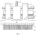
- Figure 9 shows a plan view of this needle bar 2 with bearing blocks 1, which on the vertically one above the other guide rods 9 are attached.
- the guide rods 9 are tufted up and down by the lifting mechanism 12 moved, as indicated by arrow 15. This movement is about the Transfer bearing blocks 1 to the needle bar 2 and the perforated strips 8.
- the area of the needle bar 2 is a plurality of needle modules 10 lying side by side attached, the needles 13 according to the movement of the lifting mechanism 12 in the Pierce carrier material, not shown.
- the bearing elements 4 of the bearing blocks 1 still allow the movement of the needle bar across the tuft direction, as through the Arrows 14 indicated, so that with the help of an offset device, not shown Needle bar 2 can be moved transversely to the tuft direction.
Landscapes
- Engineering & Computer Science (AREA)
- Chemical & Material Sciences (AREA)
- Materials Engineering (AREA)
- Textile Engineering (AREA)
- Nonwoven Fabrics (AREA)
- Laminated Bodies (AREA)
- Knitting Machines (AREA)
- Sewing Machines And Sewing (AREA)
Abstract
Description
- Fig. 1:
- einen Querschnitt durch einen Lagerblock mit L-förmiger Nadelbarre aus mehreren Werkstofflagen eines Faserverbundwerkstoffes
- Fig. 2:
- einen Querschnitt durch eine L-förmige Nadelbarre aus mehreren Werkstofflagen eines Faserverbundwerkstoffes
- Fig. 3:
- einen Querschnitt durch einen Lagerblock mit L-förmiger Nadelbarre aus einer Werkstofflage eines Faserverbundwerkstoffes
- Fig. 4:
- einen Querschnitt durch eine L-förmige Nadelbarre aus einer Werkstofflage eines Faserverbundwerkstoffes
- Fig. 5:
- einen Querschnitt durch einen Lagerblock mit T-förmiger Nadelbarre aus mehreren Werkstofflagen eines Faserverbundwerkstoffes
- Fig. 6:
- einen Querschnitt durch einen Lagerblock mit T-förmiger Nadelbarre aus einer Werkstofflage eines Faserverbundwerkstoffes
- Fig. 7:
- einen Querschnitt durch eine T-förmige Nadelbarre aus einer Werkstofflage eines Faserverbundwerkstoffes
- Fig. 8:
- einen Querschnitt durch einen Lagerblock mit vertikal übereinander angeordneten Führungsstangen und Nadelbarre
- Fig. 9:
- eine Aufsicht auf einen Lagerblock mit vertikal übereinander angeordneten Führungsstangen und Nadelbarre.
- 1
- Lagerblock
- 2
- Nadelbarre
- 3
- Füllstoff
- 4
- Lagerelemente
- 5a - c
- Werkstofflagen des Faserverbundwerkstoffs
- 6
- Gewindeeinsatz
- 7
- Zwischenstück
- 8
- Lochleiste
- 9
- Führungsstange
- 10
- Nadelmodul
- 11
- Faden
- 12
- Hubmechanik
- 13
- Nadeln
- 14
- Pfeil
- 15
- Pfeil
Claims (18)
- Tuftingmaschine mit einer Nadelbarre (2) zur Aufnahme von Nadelmodulen (10) und mit Lagerblöcken (1) zur Führung von die Nadelbarre (2) tragenden, parallel zueinander verlaufenden Führungsstangen (9),
wobei die Lagerblöcke (1) zur Führung jeder Führungsstange (9) mindestens ein Lagerelement (4) aufweisen,
dadurch gekennzeichnet, dass die Nadelbarre (2) und/oder die Lagerblöcke (1) zumindest teilweise aus Faserverbundwerkstoff gebildet sind und
dass die Nadelbarre (2) und die Lagerblöcke (1) einstückig ausgebildet sind. - Tuftingmaschine nach Anspruch 1, dadurch gekennzeichnet, dass der Faserverbundwerkstoff Karbon als Fasermaterial aufweist.
- Tuftingmaschine nach einem der vorhergehenden Ansprüche, dadurch gekennzeichnet, dass die Führungsstangen (9) in voneinander abweichenden Höhenlagen angeordnet sind.
- Tuftingmaschine nach einem der vorhergehenden Ansprüche, dadurch gekennzeichnet, dass die Lagerblöcke (1) jeweils ein kastenförmiges, zumindest zum Teil mit einem formstabilen Füllstoff (3) gefülltes und die Lagerelemente (4) aufnehmendes Hohlprofil aufweisen, das von einer oder mehreren Lagen (5) des Faserverbundwerkstoffes ganz oder zumindest überwiegend umhüllt ist.
- Tuftingmaschine nach einem der Ansprüche 1 bis 3, dadurch gekennzeichnet, dass die Lagerblöcke (1) aus mindestens einer die Lagerelemente (4) umschließenden Lage (5) aus Faserverbundwerkstoff gebildet sind.
- Tuftingmaschine nach Anspruch 4 oder 5, dadurch gekennzeichnet, dass die Lagen (5) der Lagerblöcke (1) von diesen stegförmig abstehen und die Nadelbarre (2) bilden.
- Tuftingmaschine nach einem der vorhergehenden Ansprüche, dadurch gekennzeichnet, dass zumindest eine Lage (5) des Faserverbundwerkstoffes von ihrem Anfang bis zu ihrem Ende ohne Unterbrechung den Lagerblock (1), an diesem anliegend, umfährt und dabei in einem gegenüber dem Lagerblock (1) vorstehenden Bereich die Nadelbarre (2) bildet.
- Tuftingmaschine nach Anspruch 7, dadurch gekennzeichnet, dass die Nadelbarre (2) mittig am Lagerblock (1) vorsteht.
- Tuftingmaschine nach Anspruch 7, dadurch gekennzeichnet, dass die Nadelbarre (2) seitlich am Lagerblock (1) vorsteht.
- Tuftingmaschine nach einem der vorhergehenden Ansprüche, dadurch gekennzeichnet, dass an dem unteren Ende der Nadelbarre (2) zumindest eine der Lagen (5) des Faserverbundwerkstoffes als winklig hervorstehende Lochleiste (8) zur Fadenführung ausgebildet ist.
- Tuftingmaschine nach einem der vorhergehenden Ansprüche, dadurch gekennzeichnet, dass die Nadelbarre (2) in ihrem zur Befestigung der Nadelmodule (10) vorgesehenen Bereich Bohrungen aufweist.
- Tuftingmaschine nach Anspruch 11, dadurch gekennzeichnet, dass Gewindeeinsätze (6) in die Bohrungen eingelassen sind.
- Tuftingmaschine nach einem der vorhergehenden Ansprüche, dadurch gekennzeichnet, dass an der Nadelbarre (2) und/oder den Lagerblöcken (1) Lochleisten (8) aus Faserverbundwerkstoff abgestützt sind.
- Tuftingmaschine nach Anspruch 13, dadurch gekennzeichnet, dass der Faserverbundwerkstoff der Lochleisten (8) Karbon als Fasermaterial aufweist.
- Tuftingmaschine nach Anspruch 14, dadurch gekennzeichnet, dass in die Löcher der Lochleisten (8) Keramikeinsätze eingesetzt sind.
- Tuftingmaschine nach einem der vorhergehenden Ansprüche, dadurch gekennzeichnet, dass die Lagerelemente (4) der Lagerblöcke (1) jeweils Lagerhülsen aus Keramik sind.
- Tuftingmaschine nach einem der vorhergehenden Ansprüche 1 bis 15, dadurch gekennzeichnet, das die Lagerelemente (4) der Lagerblöcke (1) jeweils Rollenlager sind.
- Tuftingmaschine nach einem der vorhergehenden Ansprüche, dadurch gekennzeichnet, dass die Nadelbarre (2) als Austausch für eine herkömmliche Nadelbarre die gleichen geometrischen Anschlusswerte wie diese aufweist.
Applications Claiming Priority (2)
| Application Number | Priority Date | Filing Date | Title |
|---|---|---|---|
| DE10255293 | 2002-11-26 | ||
| DE2002155293 DE10255293B4 (de) | 2002-11-26 | 2002-11-26 | Tuftingmaschine |
Publications (3)
| Publication Number | Publication Date |
|---|---|
| EP1424426A2 true EP1424426A2 (de) | 2004-06-02 |
| EP1424426A3 EP1424426A3 (de) | 2006-04-05 |
| EP1424426B1 EP1424426B1 (de) | 2008-01-23 |
Family
ID=32240471
Family Applications (1)
| Application Number | Title | Priority Date | Filing Date |
|---|---|---|---|
| EP20030025528 Expired - Lifetime EP1424426B1 (de) | 2002-11-26 | 2003-11-07 | Tuftingmaschine |
Country Status (2)
| Country | Link |
|---|---|
| EP (1) | EP1424426B1 (de) |
| DE (1) | DE10255293B4 (de) |
Cited By (1)
| Publication number | Priority date | Publication date | Assignee | Title |
|---|---|---|---|---|
| EP2072652A1 (de) * | 2007-12-20 | 2009-06-24 | F. & L. Bachmann AG | Modul, insbesondere Tuftingmodul sowie Verfahren zum Herstellen eines solchen Moduls |
Family Cites Families (10)
| Publication number | Priority date | Publication date | Assignee | Title |
|---|---|---|---|---|
| DE7901112U1 (de) * | 1979-01-17 | 1979-04-12 | Zieseniss, Karl-Heinz, 6430 Bad Hersfeld | Nadelstangensegment fuer tufting- maschinen |
| DE3840531C1 (de) * | 1988-12-01 | 1990-05-10 | Mayer Textilmaschf | Kettenwirkmaschine mit mindestens einer Barre |
| DE4111108C2 (de) * | 1991-04-05 | 1993-10-07 | Erbsloeh Julius & August | Als geschlossenes Hohlprofil aus verstärktem Kunststoff ausgebildeter Träger |
| GB9110506D0 (en) * | 1991-05-15 | 1991-07-03 | Cobble Blackburn Ltd | Improvements in or relating to tufting machinery |
| DE4302858C1 (de) * | 1993-02-02 | 1994-06-01 | Mayer Textilmaschf | Verfahren zum Herstellen einer Nadelbarre |
| DE19528149A1 (de) * | 1995-08-01 | 1997-02-06 | Deutsches Teppich Forschungsin | Tuftingverfahren sowie Tuftingmaschine zu seiner Durchführung |
| DE19713195A1 (de) * | 1997-03-27 | 1998-10-01 | Voith Sulzer Papiermasch Gmbh | Tragbalken |
| GB9911667D0 (en) * | 1999-05-19 | 1999-07-21 | Cobble Blackburn Ltd | A tufting machine |
| GB2357301A (en) * | 1999-12-16 | 2001-06-20 | Cobble Blackburn Ltd | Tufting machine with independent control of the needle bars |
| JP2001178977A (ja) * | 1999-12-24 | 2001-07-03 | Juki Corp | ミシン用部品 |
-
2002
- 2002-11-26 DE DE2002155293 patent/DE10255293B4/de not_active Expired - Fee Related
-
2003
- 2003-11-07 EP EP20030025528 patent/EP1424426B1/de not_active Expired - Lifetime
Cited By (1)
| Publication number | Priority date | Publication date | Assignee | Title |
|---|---|---|---|---|
| EP2072652A1 (de) * | 2007-12-20 | 2009-06-24 | F. & L. Bachmann AG | Modul, insbesondere Tuftingmodul sowie Verfahren zum Herstellen eines solchen Moduls |
Also Published As
| Publication number | Publication date |
|---|---|
| EP1424426A3 (de) | 2006-04-05 |
| DE10255293B4 (de) | 2006-03-23 |
| DE10255293A1 (de) | 2004-06-17 |
| EP1424426B1 (de) | 2008-01-23 |
Similar Documents
| Publication | Publication Date | Title |
|---|---|---|
| EP0609664B1 (de) | Trockensieb sowie Verfahren zu dessen Herstellung | |
| DE4107653A1 (de) | Entwaesserungseinrichtung fuer die nasspartie einer papiermaschine | |
| DE3608193A1 (de) | Abstreifvorrichtung zum reinigen von foerderbaendern | |
| DE3628282A1 (de) | Stationaere stuetzvorrichtung | |
| DE19600031A1 (de) | Schnell einstellbarer, hochbelastbarer Maschinenträger | |
| DE3334040A1 (de) | Ein- oder mehrschlosssystem fuer flachstrickmaschinen | |
| DE102018107868B4 (de) | Drahtbasiertes additives Fertigungssystem | |
| DE2739361A1 (de) | Breitstreckwalze | |
| EP2623652A1 (de) | Wirkwerkzeugbarre und Verfahren zum Erzeugen einer Wirkwerkzeugbarre | |
| DE10015730A1 (de) | Platine für eine insbesondere nach der Relativtechnik arbeitende Strickmaschine und mit einer derartigen Platine ausgerüstete Strickmaschine | |
| DE2530872A1 (de) | Verfahren und vorrichtung zum nadeln von textilgut | |
| DE19534486C1 (de) | Gliederband insbesondere für Papiermaschinen | |
| DE3315417C1 (de) | Verfahren und Vorrichtungen zum Wickeln und Formen von Wendeln aus elastischem Kunststoff- oder Metalldraht,vorzugsweise zum Fuegen von Flaechengebilden | |
| DE7723785U1 (de) | Vorrichtung zum ausrichten von mit einem bindemittel versehenen, lignozellulosehaltigen teilchen | |
| EP1424426B1 (de) | Tuftingmaschine | |
| DE2731269C2 (de) | Faservlies sowie Verfahren und Vorrichtung zur Herstellung des Vlieses | |
| DE4431055A1 (de) | Vorrichtung zum Nadeln eines Vlieses | |
| DE2745793A1 (de) | Tufting-maschine | |
| DE2725573B1 (de) | Stuetzelement einer Durchbiegungseinstellwalze | |
| CH695345A5 (de) | Musterlegebarrenanordnung für Kettenwirkmaschinen. | |
| DE2737547C3 (de) | Verfahren zum Zusammensetzen eines Vlieses von Naturtabak | |
| DE3343287A1 (de) | Hochlochziegel | |
| DE2255388A1 (de) | Foerderkette fuer die nadelstaebe einer vorrichtung fuer den verzug von textilfasern | |
| DE102018109212B4 (de) | Verfahren und Anlage zum Herstellen einer Faserpreform sowie Verfahren zur Herstellung eines Faserverbundbauteils | |
| EP0904865A2 (de) | Verfahren und Vorrichtung zum Herstellen eines Metallbandes mit über seine Breite verschieden dicken Bereichen |
Legal Events
| Date | Code | Title | Description |
|---|---|---|---|
| PUAI | Public reference made under article 153(3) epc to a published international application that has entered the european phase |
Free format text: ORIGINAL CODE: 0009012 |
|
| AK | Designated contracting states |
Kind code of ref document: A2 Designated state(s): AT BE BG CH CY CZ DE DK EE ES FI FR GB GR HU IE IT LI LU MC NL PT RO SE SI SK TR |
|
| AX | Request for extension of the european patent |
Extension state: AL LT LV MK |
|
| PUAL | Search report despatched |
Free format text: ORIGINAL CODE: 0009013 |
|
| AK | Designated contracting states |
Kind code of ref document: A3 Designated state(s): AT BE BG CH CY CZ DE DK EE ES FI FR GB GR HU IE IT LI LU MC NL PT RO SE SI SK TR |
|
| AX | Request for extension of the european patent |
Extension state: AL LT LV MK |
|
| 17P | Request for examination filed |
Effective date: 20061004 |
|
| AKX | Designation fees paid |
Designated state(s): AT BE BG CH LI |
|
| RBV | Designated contracting states (corrected) |
Designated state(s): BE FR GB NL |
|
| REG | Reference to a national code |
Ref country code: DE Ref legal event code: 8566 |
|
| GRAP | Despatch of communication of intention to grant a patent |
Free format text: ORIGINAL CODE: EPIDOSNIGR1 |
|
| GRAS | Grant fee paid |
Free format text: ORIGINAL CODE: EPIDOSNIGR3 |
|
| GRAA | (expected) grant |
Free format text: ORIGINAL CODE: 0009210 |
|
| AK | Designated contracting states |
Kind code of ref document: B1 Designated state(s): BE FR GB NL |
|
| REG | Reference to a national code |
Ref country code: GB Ref legal event code: FG4D Free format text: NOT ENGLISH |
|
| GBT | Gb: translation of ep patent filed (gb section 77(6)(a)/1977) |
Effective date: 20080403 |
|
| ET | Fr: translation filed | ||
| PLBE | No opposition filed within time limit |
Free format text: ORIGINAL CODE: 0009261 |
|
| STAA | Information on the status of an ep patent application or granted ep patent |
Free format text: STATUS: NO OPPOSITION FILED WITHIN TIME LIMIT |
|
| 26N | No opposition filed |
Effective date: 20081024 |
|
| PGFP | Annual fee paid to national office [announced via postgrant information from national office to epo] |
Ref country code: NL Payment date: 20090520 Year of fee payment: 6 |
|
| REG | Reference to a national code |
Ref country code: FR Ref legal event code: ST Effective date: 20090731 |
|
| PGFP | Annual fee paid to national office [announced via postgrant information from national office to epo] |
Ref country code: BE Payment date: 20090526 Year of fee payment: 6 |
|
| PGFP | Annual fee paid to national office [announced via postgrant information from national office to epo] |
Ref country code: GB Payment date: 20090528 Year of fee payment: 6 |
|
| BERE | Be: lapsed |
Owner name: DEUTSCHES TEPPICH-FORSCHUNGSINSTITUT E.V. Effective date: 20091130 |
|
| REG | Reference to a national code |
Ref country code: NL Ref legal event code: V1 Effective date: 20100601 |
|
| GBPC | Gb: european patent ceased through non-payment of renewal fee |
Effective date: 20091107 |
|
| PG25 | Lapsed in a contracting state [announced via postgrant information from national office to epo] |
Ref country code: NL Free format text: LAPSE BECAUSE OF NON-PAYMENT OF DUE FEES Effective date: 20100601 Ref country code: BE Free format text: LAPSE BECAUSE OF NON-PAYMENT OF DUE FEES Effective date: 20091130 |
|
| PG25 | Lapsed in a contracting state [announced via postgrant information from national office to epo] |
Ref country code: GB Free format text: LAPSE BECAUSE OF NON-PAYMENT OF DUE FEES Effective date: 20091107 |
|
| PG25 | Lapsed in a contracting state [announced via postgrant information from national office to epo] |
Ref country code: FR Free format text: LAPSE BECAUSE OF NON-PAYMENT OF DUE FEES Effective date: 20081130 |