EP0904865A2 - Verfahren und Vorrichtung zum Herstellen eines Metallbandes mit über seine Breite verschieden dicken Bereichen - Google Patents
Verfahren und Vorrichtung zum Herstellen eines Metallbandes mit über seine Breite verschieden dicken Bereichen Download PDFInfo
- Publication number
- EP0904865A2 EP0904865A2 EP98118246A EP98118246A EP0904865A2 EP 0904865 A2 EP0904865 A2 EP 0904865A2 EP 98118246 A EP98118246 A EP 98118246A EP 98118246 A EP98118246 A EP 98118246A EP 0904865 A2 EP0904865 A2 EP 0904865A2
- Authority
- EP
- European Patent Office
- Prior art keywords
- belt
- band
- roll
- strip
- work
- Prior art date
- Legal status (The legal status is an assumption and is not a legal conclusion. Google has not performed a legal analysis and makes no representation as to the accuracy of the status listed.)
- Granted
Links
Images
Classifications
-
- B—PERFORMING OPERATIONS; TRANSPORTING
- B21—MECHANICAL METAL-WORKING WITHOUT ESSENTIALLY REMOVING MATERIAL; PUNCHING METAL
- B21H—MAKING PARTICULAR METAL OBJECTS BY ROLLING, e.g. SCREWS, WHEELS, RINGS, BARRELS, BALLS
- B21H8/00—Rolling metal of indefinite length in repetitive shapes specially designed for the manufacture of particular objects, e.g. checkered sheets
-
- B—PERFORMING OPERATIONS; TRANSPORTING
- B21—MECHANICAL METAL-WORKING WITHOUT ESSENTIALLY REMOVING MATERIAL; PUNCHING METAL
- B21B—ROLLING OF METAL
- B21B1/00—Metal-rolling methods or mills for making semi-finished products of solid or profiled cross-section; Sequence of operations in milling trains; Layout of rolling-mill plant, e.g. grouping of stands; Succession of passes or of sectional pass alternations
- B21B1/08—Metal-rolling methods or mills for making semi-finished products of solid or profiled cross-section; Sequence of operations in milling trains; Layout of rolling-mill plant, e.g. grouping of stands; Succession of passes or of sectional pass alternations for rolling structural sections, i.e. work of special cross-section, e.g. angle steel
- B21B1/0805—Flat bars, i.e. having a substantially rectangular cross-section
-
- B—PERFORMING OPERATIONS; TRANSPORTING
- B21—MECHANICAL METAL-WORKING WITHOUT ESSENTIALLY REMOVING MATERIAL; PUNCHING METAL
- B21B—ROLLING OF METAL
- B21B1/00—Metal-rolling methods or mills for making semi-finished products of solid or profiled cross-section; Sequence of operations in milling trains; Layout of rolling-mill plant, e.g. grouping of stands; Succession of passes or of sectional pass alternations
- B21B1/22—Metal-rolling methods or mills for making semi-finished products of solid or profiled cross-section; Sequence of operations in milling trains; Layout of rolling-mill plant, e.g. grouping of stands; Succession of passes or of sectional pass alternations for rolling plates, strips, bands or sheets of indefinite length
- B21B1/227—Surface roughening or texturing
Definitions
- the invention relates to a method for producing a Metal tape with different thicknesses across its width Areas and a device for carrying out the Procedure.
- Tailored Blanks For reasons of economical use of material and a load-dependent dimensioning of components, components have been used for a long time that have different thicknesses over their area and / or length (metal forming technology, 7th Aachen Steel Colloquium from March 26th to 27th 1992, 4.2 Rolling Load-Optimized Longitudinal Profiles "from B.Hachmann, R.Kopp, Aachen). The preliminary products of such components are called Tailored Blanks ". In practice, there are two fundamentally different manufacturing processes for the production of such tailored blanks.
- a tape is in its thickness in sections in an deliverable Roll gap of a roll stand reduced. From a such tape with different thickness can then Cut out blanks for the desired components become.
- the advantages of such a method exist in that the transitions from the smallest strip thickness to greatest strip thickness are steady.
- the disadvantage is that the transitions are long because of the delivery of the roll gap cannot take place suddenly.
- Another disadvantage is that for the delivery of the Roll gap very large forces are required.
- a Roll stand must be specially designed to Example of a special compensation device for these elongations of the Have roll stand.
- this Process the usual roll speed of do not use for several 100 meters. That is why such process for the production of tailored blanks not suitable.
- the object of the invention is a method and an apparatus for producing a Metal tape with different over its width To create thickness ranges and a smooth transition that a low manufacturing cost at one comparatively high production speed allowed.
- This task is done with regard to the procedure solved that in a band with constant across its width Thickness at least one in the longitudinal direction of the tape extending strip of small thickness molded thereby is that the tape by at least one, of one Front of a work roll and a support roller formed drawing gap is drawn, the work roll with its axis of rotation so inclined to the band plane is employed that when pulling the tape Work roller with its face on the belt a force exercises transversely to the tape longitudinal direction.
- the device for This method is carried out according to the invention characterized by guide and traction means for the belt and at least one drawing gap, each of which Front of a work roll and a backup roll is formed, the work roll with its axis of rotation is so inclined to the band plane that at The end of the belt runs through the belt a force on the belt transverse to the belt longitudinal direction exercises.
- the dimensioning of the Work roll in itself influence the dimensioning of the thinned strip.
- the axis of rotation of the Work roll is tilted in different directions.
- the axes of the work rolls are both around an axis parallel to the longitudinal axis of the belt as well one parallel to the band plane and perpendicular to the Belt longitudinal axis tilted axis.
- the Force directions Be with neighboring work rolls whose axes of rotation towards each other and in the direction of pull Band tipped, then tensile forces occur between the two Work rolls on.
- Tractive forces occur between the two Work rolls even if their axes of rotation away from each other and against the direction of the tape be tilted.
- step between the work rolls Compressive forces when the axes of rotation of the work rolls away from each other and tilted in the direction of pull or towards each other and against the direction of pull.
- the task is further through a device with the Features of claim 5 solved.
- the profile is the molded areas including the geometry of the Work roll decisive.
- a preferred Embodiment of the invention instructs each work roll a tapered ring surface as the engagement surface on. With such a conical ring surface as Above all, the angle of inclination can be applied of the molded strip.
- the device can be driven with work rolls or freely rotatable and then dragged through the belt Work rolls work.
- the method is applied to warm Steel belt with a temperature of> 600 ° C. Also it will considered advantageous if the procedure is based on recrystallized annealed cold steel strip applied after forming in the forming area is heated above 600 ° C.
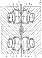
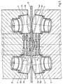
- each device has two pairs each Drawing gap 1,2 between the forming rolls 3,4,5,6.
- the area of engagement of these work rolls 3,4,5,6 is located on the front side and is from Tapered ring surfaces 3a, 4a, 5a, 6a formed.
- the work rolls 3,4,5,6 consist of individual sections in Axis direction of decreasing diameter together, namely in particular from frustoconical sections.
- the Work rolls 3,4,5,6 are in a frame 7,8 Radial and axial bearings freely rotatable. While she in the exemplary embodiment in FIG.
- Both exemplary embodiments have in common that the Work rolls with their axes of rotation 3b, 4b, 5b, 6b twice are tilted, on the one hand towards each other and to the others in the direction of tension of the belt B.
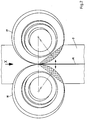
- FIG. 2 differs of those of Figures 4 and 5 only in that the Work rolls 17, 18 arranged directly next to each other are. You can then roll on each other and thus yourself support each other.
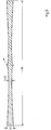
- Work rolls 17, 18 creates a band, as in Cross section is shown in Figure 3.
- the one at this Band slightly increased center area M can be in one subsequent rolling process can be leveled. Should for Compensating for the spread temporarily a bead in the band B can be shaped, this can be advantageous Way by means of a slide shoe, not shown here take place, which in the free gusset area between the work rolls 17, 18 is arranged.
Landscapes
- Engineering & Computer Science (AREA)
- Mechanical Engineering (AREA)
- Shaping Metal By Deep-Drawing, Or The Like (AREA)
- Metal Rolling (AREA)
- Bending Of Plates, Rods, And Pipes (AREA)
Abstract
Description
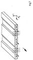
- Figur 1
- ein Band mit zwei dünneren Streifen in isometrischer Darstellung und im Schnitt,
- Figur 2
- ein Band mit zwei aneinanderstoßenden ausgedünnten Streifen mit zwei Arbeitswalzen in Aufsicht,
- Figur 3
- das Band gemäß Figur 2 im Querschnitt,
- Figur 4
- eine Vorrichtung zum Herstellen eines Bandes mit zwei ausgedünnten Bereichen im Querschnitt in einer ersten Ausführung,
- Figur 5
- die Vorrichtung zum Herstellen eines
Metallbandes mit zwei ausgedünnten Bereichen im
Querschnitt in einer zweiten Ausführung
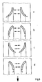
und - Figur 6
- verschiedene Eingriffsbereiche bei unterschiedlicher Anstellung der Arbeitswalzen der Figuren 2,4 und 5 an einem Band.
Claims (12)
- Verfahren zum Herstellen eines Metallbandes mit über seine Breite verschieden dicken Bereichen, wobei in ein Band (B) mit über seine Breite konstanter Dicke mindestens ein sich in Bandlängsrichtung erstreckender Streifen geringer Dicke dadurch eingeformt wird, daß das Band (B) durch mindestens einen von einer Stirnseite einer Arbeitswalze und einer Stützwalze gebildeten Ziehspalt gezogen wird, wobei die Arbeitswalze mit ihrer Drehachse derart geneigt zur Bandebene angestellt ist, daß bei Durchzug des Bandes (B) die Arbeitswalze mit ihrer Stirnseite auf das Band (B) eine Kraft quer zur Bandlängsrichtung ausübt.
- Verfahren nach Anspruch 1,
dadurch gekennzeichnet, daß parallel zu dem Streifen geringerer Dicke gleichzeitig ein weiterer Streifen durch Ziehen des Bandes (B) durch einen dem ersten Ziehspalt spiegelbildlich entsprechenden zweiten Ziehspalt eingeformt wird, wobei die dabei auf das Band ausgeübten Kräfte quer zur Bandlängsrichtung einander kompensieren. - Verfahren nach Anspruch 1 oder 2,
dadurch gekennzeichnet, daß als Stützwalze eine weitere Arbeitswalze verwendet wird, so daß von beiden Seiten des Bandes (B) mit gleichartigen, zur Bandebene geneigt angestellten Arbeitswalzen umformend auf das Band (B) eingewirkt wird. - Verfahren nach Anspruch 1 oder 2,
dadurch gekennzeichnet, daß bei zwei eine Breitung des Bandes zwischen sich bewirkenden Ziehspalten zwischen den Ziehspalten eine diese Breitung kompensierende Sicke (S) eingeformt wird. - Vorrichtung zum Herstellen eines Metallbandes mit über seine Breite verschieden dicken Bereichen zur Durchführung des Verfahrens nach Anspruch 1 mit Führungs- und Zugmitteln für das Band (B) und mindestens einem Ziehspalt (1,2), der jeweils von der Stirnseite einer Arbeitswalze (3,6) und einer Stützwalze gebildet wird, wobei die Arbeitswalze (3,6) mit ihrer Drehachse (3b,6b) derart geneigt zur Bandebene angestellt ist, daß bei Durchzug des Bandes (B) die Arbeitswalze (3) mit ihrer Stirnseite auf das Band (B) eine Kraft quer zur Bandlängsrichtung ausübt.
- Vorrichtung nach Anspruch 5,
dadurch gekennzeichnet, daß als Stützwalze eine weitere Arbeitswalze (4,5) vorgesehen ist, so daß jeder Ziehspalt (1,2) von jeweils zwei gleichartigen, zur Bandebene geneigt angestellten Arbeitswalzen (3,4,5,6) gebildet wird. - Vorrichtung nach einem der Ansprüche 5 oder 6,
dadurch gekennzeichnet, daß die Achsen der Arbeitswalzen sowohl um eine Achse parallel zur Bandlängsachse als auch um eine parallel zur Bandebene und senkrecht zur Bandlängsachse verlaufende Achse gekippt sind. - Vorrichtung nach Anspruch 7,
dadurch gekennzeichnet, daß die Arbeitswalzen (3,4,5,6) sich mit ihren Mänteln unmittelbar oder mittelbar über Laufringe (9,10,12,13) aneinander abstützen. - Vorrichtung nach Anspruch 8,
dadurch gekennzeichnet, daß bei mittelbarer Abstützung der Arbeitswalzen (3,4,5,6) zwischen den Ziehspalten (1,2) auf einer Bandseite eine Formwalze (15) zum Einformen einer Sicke (S) vorgesehen ist. - Vorrichtung nach Anspruch 8 oder 9,
dadurch gekennzeichnet, daß die Mäntel der Arbeitswalzen (3,4,5,6) kegelig sind. - Vorrichtung nach Anspruch 10,
dadurch gekennzeichnet, daß zur mittelbaren Abstützung der Arbeitswalzen (3,4,5,6) mehrere konzentrisch übereinander angeordnete und unabhängig voneinander drehbare Laufringe (9,10,12,13) die Arbeitswalzen an ihren kegeligen Mänteln abstützen. - Vorrichtung nach einem der Ansprüche 6 bis 11,
dadurch gekennzeichnet, daß jede Arbeitswalze (3,4,5,6) an ihrer dem Ziehspalt zugeordneten Stirnseite eine Kegelringfläche (3a,4a,5a,6a) als Eingriffsfläche aufweist.
Applications Claiming Priority (2)
| Application Number | Priority Date | Filing Date | Title |
|---|---|---|---|
| DE19743093A DE19743093C1 (de) | 1997-09-30 | 1997-09-30 | Verfahren und Vorrichtung zum Herstellen eines Metallbandes mit über seine Breite verschieden dicken Bereichen |
| DE19743093 | 1997-09-30 |
Publications (3)
| Publication Number | Publication Date |
|---|---|
| EP0904865A2 true EP0904865A2 (de) | 1999-03-31 |
| EP0904865A3 EP0904865A3 (de) | 2001-11-14 |
| EP0904865B1 EP0904865B1 (de) | 2004-02-11 |
Family
ID=7844076
Family Applications (1)
| Application Number | Title | Priority Date | Filing Date |
|---|---|---|---|
| EP98118246A Expired - Lifetime EP0904865B1 (de) | 1997-09-30 | 1998-09-25 | Verfahren und Vorrichtung zum Herstellen eines Metallbandes mit über seine Breite verschieden dicken Bereichen |
Country Status (3)
| Country | Link |
|---|---|
| US (1) | US5953949A (de) |
| EP (1) | EP0904865B1 (de) |
| DE (2) | DE19743093C1 (de) |
Cited By (1)
| Publication number | Priority date | Publication date | Assignee | Title |
|---|---|---|---|---|
| WO2010094538A1 (de) * | 2009-02-19 | 2010-08-26 | Thyssenkrupp Steel Europe Ag | Verfahren zur herstellung eines pressgehärteten metallbauteils |
Families Citing this family (5)
| Publication number | Priority date | Publication date | Assignee | Title |
|---|---|---|---|---|
| US8069407B1 (en) | 1998-12-08 | 2011-11-29 | Yodlee.Com, Inc. | Method and apparatus for detecting changes in websites and reporting results to web developers for navigation template repair purposes |
| DE102007047875A1 (de) * | 2007-11-28 | 2009-06-04 | Hilti Aktiengesellschaft | Profil |
| WO2010009751A1 (de) | 2008-07-24 | 2010-01-28 | Welser Profile Ag | Verfahren zur herstellung eines profils mit mindestens einer verdickten profilkante |
| BE1019321A5 (nl) | 2010-04-29 | 2012-06-05 | Levin Henri Bvba Ets | Spanring en vatsamenstel. |
| FR2973490B1 (fr) * | 2011-03-31 | 2018-05-18 | Valeo Systemes Thermiques | Tube pour echangeur thermique, echangeur thermique et procede d'obtention correspondants |
Family Cites Families (6)
| Publication number | Priority date | Publication date | Assignee | Title |
|---|---|---|---|---|
| IT988066B (it) * | 1971-08-24 | 1975-04-10 | Nippon Steel Corp | Laminatoio acciaio del tipo a tre rulli |
| FR2394342A1 (fr) * | 1977-06-14 | 1979-01-12 | Mi Radiotekh Inst | Procede de fabrication d'un ruban metallique et dispositif pour la mise en oeuvre dudit procede |
| FR2515541B1 (de) * | 1981-10-30 | 1985-05-10 | Griset Ets | |
| JPS59109466A (ja) * | 1982-12-16 | 1984-06-25 | Nissan Motor Co Ltd | 主として曲げ荷重を受ける部位に用いられる自動車用メンバの製造方法 |
| JPS59202101A (ja) * | 1983-05-04 | 1984-11-15 | Nippon Steel Corp | フランジを有する形材の圧延方法 |
| GB9300529D0 (en) * | 1993-01-13 | 1993-03-03 | Penny & Giles Blackwood Ltd | Improvements in rotary forging |
-
1997
- 1997-09-30 DE DE19743093A patent/DE19743093C1/de not_active Expired - Fee Related
-
1998
- 1998-09-25 EP EP98118246A patent/EP0904865B1/de not_active Expired - Lifetime
- 1998-09-25 US US09/160,872 patent/US5953949A/en not_active Expired - Fee Related
- 1998-09-25 DE DE59810737T patent/DE59810737D1/de not_active Expired - Fee Related
Cited By (2)
| Publication number | Priority date | Publication date | Assignee | Title |
|---|---|---|---|---|
| WO2010094538A1 (de) * | 2009-02-19 | 2010-08-26 | Thyssenkrupp Steel Europe Ag | Verfahren zur herstellung eines pressgehärteten metallbauteils |
| CN102317001B (zh) * | 2009-02-19 | 2016-02-24 | 蒂森克虏伯钢铁欧洲股份公司 | 用于制造压力淬火的金属部件的方法 |
Also Published As
| Publication number | Publication date |
|---|---|
| EP0904865A3 (de) | 2001-11-14 |
| DE19743093C1 (de) | 1998-12-17 |
| US5953949A (en) | 1999-09-21 |
| DE59810737D1 (de) | 2004-03-18 |
| EP0904865B1 (de) | 2004-02-11 |
Similar Documents
| Publication | Publication Date | Title |
|---|---|---|
| DE2813636C3 (de) | Verfahren und Einrichtung zur Herstellung von Profilen aus Metall, vornehmlich von Stahlprofilen | |
| DE3873103T2 (de) | Metallwalzverfahren mit in axialrichtung verschiebbaren arbeitswalzen. | |
| DE10041280C2 (de) | Verfahren und Vorrichtung zum flexiblen Walzen eines Metallbandes | |
| DE3885019T2 (de) | Verfahren und Vorrichtung zum Richten eines metallischen Bandes. | |
| DE1940341B2 (de) | Verfahren und Einrichtung zum Herstellen von Metalleisten, insbesondere von rohrförmigen Schweißelektroden, aus einem Stabmaterial | |
| DE3103530A1 (de) | Verfahren zum ineinandergreifen von kalibern, die fuer die stauchstiche eines universal-walzvorgangs von profilstuecken bestimmt sind, sowie walzen, walzgerueste und walzwerke zur durchfuehrung dieses verfahrens | |
| DE1809638A1 (de) | Vorrichtung zum Bearbeiten von Blech- oder Bandmaterial | |
| DE3780453T2 (de) | Walze zum stauchen von flanschen eines walzprofils. | |
| EP0904865B1 (de) | Verfahren und Vorrichtung zum Herstellen eines Metallbandes mit über seine Breite verschieden dicken Bereichen | |
| DE1919815A1 (de) | Verfahren und Vorrichtung zum kontinuierlichen Walzen duenner Baender | |
| DE3417500C2 (de) | ||
| DE1427875B2 (de) | Walzwerk zum Walzen von Profilen mit dünnen Wandstärken, wie Doppel-T-Trägern od. dgl | |
| DE2848295C2 (de) | Kalander zur Herstellung von thermoplastischer Folien | |
| DE102010005758B3 (de) | Vorrichtung und Verfahren zum Führen von miteinander entlang ihrer Längskanten zu fügender Bänder | |
| DE69004558T2 (de) | Vorrichtung zum Walzen und Längsteilen ohne Verwindung und Verfahren zur Herstellung von Bewehrungsstäben. | |
| DE3302333C2 (de) | ||
| EP0264849A2 (de) | Verfahren und Anordnung zum Walzen von strangförmigem, profilierten Walzgut innerhalb enger Toleranzen | |
| DE1565740B2 (de) | Vorrichtung fuer die kontinuierliche herstellung leichtgewichtiger zusammengesetzter metallischer i-traeger mittels einer elektrischen widerstands-nahtschweisseinrichtung | |
| DE1779588C3 (de) | Verfahren zur kontinuierlichen Herstellung langgestreckter Schaumstoffkörper mit gekrümmter Mantelfläche und Vorrichtung zum Ausführen des Verfahrens | |
| DE69300944T2 (de) | Verfahren und Vorrichtung zum Herstellen von einzelnen runden Stangen im warmen Zustand aus warmen Mehrfachelementen. | |
| DD156066A5 (de) | Anordnung einer vielzahl von unterschiedlichen stauchkalibern auf einem walzensatz | |
| DE1527630A1 (de) | Kaliberwalzwerk | |
| DE102022004111B4 (de) | Verfahren zum Schrägwalzen von Rohlingen mit der im Walzkaliber wirkenden axialen Zugkraft | |
| DE102010048242A1 (de) | Streckwerk mit verbesserter Ausgangsunterwalze | |
| AT286214B (de) | Verfahren und Vorrichtung zum Behandeln von Gießsträngen durch Walzen |
Legal Events
| Date | Code | Title | Description |
|---|---|---|---|
| PUAI | Public reference made under article 153(3) epc to a published international application that has entered the european phase |
Free format text: ORIGINAL CODE: 0009012 |
|
| AK | Designated contracting states |
Kind code of ref document: A2 Designated state(s): AT BE CH CY DE DK ES FI FR GB GR IE IT LI LU MC NL PT SE Kind code of ref document: A2 Designated state(s): DE FR GB |
|
| AX | Request for extension of the european patent |
Free format text: AL;LT;LV;MK;RO;SI |
|
| PUAL | Search report despatched |
Free format text: ORIGINAL CODE: 0009013 |
|
| AK | Designated contracting states |
Kind code of ref document: A3 Designated state(s): AT BE CH CY DE DK ES FI FR GB GR IE IT LI LU MC NL PT SE |
|
| AX | Request for extension of the european patent |
Free format text: AL;LT;LV;MK;RO;SI |
|
| RIC1 | Information provided on ipc code assigned before grant |
Free format text: 7B 21C 37/02 A, 7B 21C 3/08 B, 7B 21C 37/08 B, 7B 21B 1/08 B, 7B 21H 7/00 B |
|
| 17P | Request for examination filed |
Effective date: 20011207 |
|
| RAP1 | Party data changed (applicant data changed or rights of an application transferred) |
Owner name: THYSSENKRUPP STAHL AG |
|
| AKX | Designation fees paid |
Free format text: DE FR GB |
|
| GRAP | Despatch of communication of intention to grant a patent |
Free format text: ORIGINAL CODE: EPIDOSNIGR1 |
|
| GRAS | Grant fee paid |
Free format text: ORIGINAL CODE: EPIDOSNIGR3 |
|
| GRAA | (expected) grant |
Free format text: ORIGINAL CODE: 0009210 |
|
| AK | Designated contracting states |
Kind code of ref document: B1 Designated state(s): DE FR GB |
|
| REG | Reference to a national code |
Ref country code: GB Ref legal event code: FG4D Free format text: NOT ENGLISH |
|
| GBT | Gb: translation of ep patent filed (gb section 77(6)(a)/1977) |
Effective date: 20040211 |
|
| REF | Corresponds to: |
Ref document number: 59810737 Country of ref document: DE Date of ref document: 20040318 Kind code of ref document: P |
|
| PG25 | Lapsed in a contracting state [announced via postgrant information from national office to epo] |
Ref country code: GB Free format text: LAPSE BECAUSE OF NON-PAYMENT OF DUE FEES Effective date: 20040925 |
|
| ET | Fr: translation filed | ||
| PLBE | No opposition filed within time limit |
Free format text: ORIGINAL CODE: 0009261 |
|
| STAA | Information on the status of an ep patent application or granted ep patent |
Free format text: STATUS: NO OPPOSITION FILED WITHIN TIME LIMIT |
|
| 26N | No opposition filed |
Effective date: 20041112 |
|
| GBPC | Gb: european patent ceased through non-payment of renewal fee |
Effective date: 20040925 |
|
| PG25 | Lapsed in a contracting state [announced via postgrant information from national office to epo] |
Ref country code: FR Free format text: LAPSE BECAUSE OF NON-PAYMENT OF DUE FEES Effective date: 20050531 |
|
| REG | Reference to a national code |
Ref country code: FR Ref legal event code: ST |
|
| PGFP | Annual fee paid to national office [announced via postgrant information from national office to epo] |
Ref country code: DE Payment date: 20061018 Year of fee payment: 9 |
|
| PG25 | Lapsed in a contracting state [announced via postgrant information from national office to epo] |
Ref country code: DE Free format text: LAPSE BECAUSE OF NON-PAYMENT OF DUE FEES Effective date: 20080401 |