EP0904865A2 - Method and apparatus for forming a metal band having areas of different thickness across its width - Google Patents
Method and apparatus for forming a metal band having areas of different thickness across its width Download PDFInfo
- Publication number
- EP0904865A2 EP0904865A2 EP98118246A EP98118246A EP0904865A2 EP 0904865 A2 EP0904865 A2 EP 0904865A2 EP 98118246 A EP98118246 A EP 98118246A EP 98118246 A EP98118246 A EP 98118246A EP 0904865 A2 EP0904865 A2 EP 0904865A2
- Authority
- EP
- European Patent Office
- Prior art keywords
- belt
- band
- roll
- strip
- work
- Prior art date
- Legal status (The legal status is an assumption and is not a legal conclusion. Google has not performed a legal analysis and makes no representation as to the accuracy of the status listed.)
- Granted
Links
Images
Classifications
-
- B—PERFORMING OPERATIONS; TRANSPORTING
- B21—MECHANICAL METAL-WORKING WITHOUT ESSENTIALLY REMOVING MATERIAL; PUNCHING METAL
- B21H—MAKING PARTICULAR METAL OBJECTS BY ROLLING, e.g. SCREWS, WHEELS, RINGS, BARRELS, BALLS
- B21H8/00—Rolling metal of indefinite length in repetitive shapes specially designed for the manufacture of particular objects, e.g. checkered sheets
-
- B—PERFORMING OPERATIONS; TRANSPORTING
- B21—MECHANICAL METAL-WORKING WITHOUT ESSENTIALLY REMOVING MATERIAL; PUNCHING METAL
- B21B—ROLLING OF METAL
- B21B1/00—Metal-rolling methods or mills for making semi-finished products of solid or profiled cross-section; Sequence of operations in milling trains; Layout of rolling-mill plant, e.g. grouping of stands; Succession of passes or of sectional pass alternations
- B21B1/08—Metal-rolling methods or mills for making semi-finished products of solid or profiled cross-section; Sequence of operations in milling trains; Layout of rolling-mill plant, e.g. grouping of stands; Succession of passes or of sectional pass alternations for rolling structural sections, i.e. work of special cross-section, e.g. angle steel
- B21B1/0805—Flat bars, i.e. having a substantially rectangular cross-section
-
- B—PERFORMING OPERATIONS; TRANSPORTING
- B21—MECHANICAL METAL-WORKING WITHOUT ESSENTIALLY REMOVING MATERIAL; PUNCHING METAL
- B21B—ROLLING OF METAL
- B21B1/00—Metal-rolling methods or mills for making semi-finished products of solid or profiled cross-section; Sequence of operations in milling trains; Layout of rolling-mill plant, e.g. grouping of stands; Succession of passes or of sectional pass alternations
- B21B1/22—Metal-rolling methods or mills for making semi-finished products of solid or profiled cross-section; Sequence of operations in milling trains; Layout of rolling-mill plant, e.g. grouping of stands; Succession of passes or of sectional pass alternations for rolling plates, strips, bands or sheets of indefinite length
- B21B1/227—Surface roughening or texturing
Definitions
- the invention relates to a method for producing a Metal tape with different thicknesses across its width Areas and a device for carrying out the Procedure.
- Tailored Blanks For reasons of economical use of material and a load-dependent dimensioning of components, components have been used for a long time that have different thicknesses over their area and / or length (metal forming technology, 7th Aachen Steel Colloquium from March 26th to 27th 1992, 4.2 Rolling Load-Optimized Longitudinal Profiles "from B.Hachmann, R.Kopp, Aachen). The preliminary products of such components are called Tailored Blanks ". In practice, there are two fundamentally different manufacturing processes for the production of such tailored blanks.
- a tape is in its thickness in sections in an deliverable Roll gap of a roll stand reduced. From a such tape with different thickness can then Cut out blanks for the desired components become.
- the advantages of such a method exist in that the transitions from the smallest strip thickness to greatest strip thickness are steady.
- the disadvantage is that the transitions are long because of the delivery of the roll gap cannot take place suddenly.
- Another disadvantage is that for the delivery of the Roll gap very large forces are required.
- a Roll stand must be specially designed to Example of a special compensation device for these elongations of the Have roll stand.
- this Process the usual roll speed of do not use for several 100 meters. That is why such process for the production of tailored blanks not suitable.
- the object of the invention is a method and an apparatus for producing a Metal tape with different over its width To create thickness ranges and a smooth transition that a low manufacturing cost at one comparatively high production speed allowed.
- This task is done with regard to the procedure solved that in a band with constant across its width Thickness at least one in the longitudinal direction of the tape extending strip of small thickness molded thereby is that the tape by at least one, of one Front of a work roll and a support roller formed drawing gap is drawn, the work roll with its axis of rotation so inclined to the band plane is employed that when pulling the tape Work roller with its face on the belt a force exercises transversely to the tape longitudinal direction.
- the device for This method is carried out according to the invention characterized by guide and traction means for the belt and at least one drawing gap, each of which Front of a work roll and a backup roll is formed, the work roll with its axis of rotation is so inclined to the band plane that at The end of the belt runs through the belt a force on the belt transverse to the belt longitudinal direction exercises.
- the dimensioning of the Work roll in itself influence the dimensioning of the thinned strip.
- the axis of rotation of the Work roll is tilted in different directions.
- the axes of the work rolls are both around an axis parallel to the longitudinal axis of the belt as well one parallel to the band plane and perpendicular to the Belt longitudinal axis tilted axis.
- the Force directions Be with neighboring work rolls whose axes of rotation towards each other and in the direction of pull Band tipped, then tensile forces occur between the two Work rolls on.
- Tractive forces occur between the two Work rolls even if their axes of rotation away from each other and against the direction of the tape be tilted.
- step between the work rolls Compressive forces when the axes of rotation of the work rolls away from each other and tilted in the direction of pull or towards each other and against the direction of pull.
- the task is further through a device with the Features of claim 5 solved.
- the profile is the molded areas including the geometry of the Work roll decisive.
- a preferred Embodiment of the invention instructs each work roll a tapered ring surface as the engagement surface on. With such a conical ring surface as Above all, the angle of inclination can be applied of the molded strip.
- the device can be driven with work rolls or freely rotatable and then dragged through the belt Work rolls work.
- the method is applied to warm Steel belt with a temperature of> 600 ° C. Also it will considered advantageous if the procedure is based on recrystallized annealed cold steel strip applied after forming in the forming area is heated above 600 ° C.
- each device has two pairs each Drawing gap 1,2 between the forming rolls 3,4,5,6.
- the area of engagement of these work rolls 3,4,5,6 is located on the front side and is from Tapered ring surfaces 3a, 4a, 5a, 6a formed.
- the work rolls 3,4,5,6 consist of individual sections in Axis direction of decreasing diameter together, namely in particular from frustoconical sections.
- the Work rolls 3,4,5,6 are in a frame 7,8 Radial and axial bearings freely rotatable. While she in the exemplary embodiment in FIG.
- Both exemplary embodiments have in common that the Work rolls with their axes of rotation 3b, 4b, 5b, 6b twice are tilted, on the one hand towards each other and to the others in the direction of tension of the belt B.
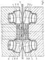
- FIG. 2 differs of those of Figures 4 and 5 only in that the Work rolls 17, 18 arranged directly next to each other are. You can then roll on each other and thus yourself support each other.
- Work rolls 17, 18 creates a band, as in Cross section is shown in Figure 3.
- the one at this Band slightly increased center area M can be in one subsequent rolling process can be leveled. Should for Compensating for the spread temporarily a bead in the band B can be shaped, this can be advantageous Way by means of a slide shoe, not shown here take place, which in the free gusset area between the work rolls 17, 18 is arranged.
Landscapes
- Engineering & Computer Science (AREA)
- Mechanical Engineering (AREA)
- Shaping Metal By Deep-Drawing, Or The Like (AREA)
- Metal Rolling (AREA)
- Bending Of Plates, Rods, And Pipes (AREA)
Abstract
Die Erfindung bezieht sich auf das Herstellen eines Metallbandes mit eingeformten dünneren Streifen. Dazu wird das Band B durch einen Ziehspalt 1,2 gezogen, der von der Stirnseite einer geneigt angestellten Arbeitsrolle 3 und einer Stützrolle 4 gebildet wird, die als Arbeitswalze ausgebildet sein kann. Beim Ziehen durch diesen Arbeitsspalt 1,2 wird von den beiden Rollen 3,4 auf das Band B eine Walzkraft und gleichzeitig eine Zugkraft quer zur Zugrichtung ausgeübt derart, daß das verdrängte Material in den auszudünnenden Bereichen praktisch ausschließlich quer zur Zugrichtung fließt. <IMAGE>The invention relates to the production of a metal strip with molded thinner strips. For this purpose, the band B is drawn through a drawing gap 1, 2, which is formed by the end face of an inclined working roll 3 and a support roll 4, which can be designed as a working roll. When pulling through this working gap 1, 2, a rolling force and at the same time a tensile force is exerted on the belt B transversely to the tensile direction in such a way that the displaced material flows practically exclusively in the areas to be thinned transverse to the tensile direction. <IMAGE>
Description
Die Erfindung betrifft ein Verfahren zum Herstellen eines Metallbandes mit über seine Breite verschieden dicken Bereichen und eine Vorrichtung zur Durchführung des Verfahrens.The invention relates to a method for producing a Metal tape with different thicknesses across its width Areas and a device for carrying out the Procedure.
Aus Gründen eines sparsamen Materialeinsatzes und einer
belastungsabhängigen Dimensionierung von Bauteilen werden
schon seit längerem Bauteile eingesetzt, die über ihre
Fläche und/oder Länge eine unterschiedliche Dicke haben
(Umformtechnik, 7.Aachener Stahlkolloquium vom 26. bis
27. März 1992, ![]()
![]()
Nach einem ersten bekannten Verfahren wird ein Band in seiner Dicke abschnittsweise in einem zustellbaren Walzspalt eines Walzgerüstes vermindert. Aus einem solchen Band mit unterschiedlicher Dicke können dann die Zuschnitte für die gewünschten Bauteile herausgeschnitten werden. Die Vorteile eines solchen Verfahrens bestehen darin, daß die Übergänge von der kleinsten Banddicke zur größten Banddicke stetig sind. Nachteilig ist jedoch, daß die Übergänge eine große Länge haben, weil die Zustellung des Walzspaltes nicht schlagartig erfolgen kann. Von Nachteil ist weiter, daß für die Zustellung des Walzspaltes sehr große Kräfte erforderlich sind. Ein Walzgerüst muß dafür besonders ausgelegt sein, zum Beispiel eine besondere Kompensationsvorrichtung für diese durch die großen Kräfte auftretenden Dehnungen des Walzgerüstes aufweisen. Außerdem läßt sich bei diesem Verfahren die sonst übliche Walzengeschwindigkeit von mehreren 100 Metern nicht ausnutzen. Deshalb ist ein solches Verfahren für die Herstellung von Tailored Blanks nicht geeignet.According to a first known method, a tape is in its thickness in sections in an deliverable Roll gap of a roll stand reduced. From a such tape with different thickness can then Cut out blanks for the desired components become. The advantages of such a method exist in that the transitions from the smallest strip thickness to greatest strip thickness are steady. The disadvantage, however, is that the transitions are long because of the delivery of the roll gap cannot take place suddenly. Another disadvantage is that for the delivery of the Roll gap very large forces are required. A Roll stand must be specially designed to Example of a special compensation device for these elongations of the Have roll stand. In addition, this Process the usual roll speed of do not use for several 100 meters. That is why such process for the production of tailored blanks not suitable.
Daneben ist es auch bekannt, ein Metallband mit über seine Breite verschiedenen Dickenbereichen dadurch herzustellen, daß in das Band mindestens ein sich in Bandlängsrichtung erstreckender Streifen geringerer Dicke mittels eines Walzenpaares eingewalzt wird, bei dem eine Walze in Achsrichtung mindestens einen Abschnitt größeren Durchmessers als im übrigen Bereich hat (DE 33 43 709 A1). Es ist nicht bekannt, daß sich ein solches Verfahren zum Herstellen von Tailored Blanks in der Praxis durchgesetzt hat.In addition, it is also known to have a metal band with over its width different thickness ranges thereby produce that in the tape at least one in Strip lengthwise extending strips of reduced thickness is rolled in by means of a pair of rollers, in which one Roll at least a section larger in the axial direction Has diameter than in the rest of the area (DE 33 43 709 A1). It is not known that such a procedure for manufacturing tailored blanks in practice has prevailed.
Dagegen ist in der Praxis ein anderes Herstellungsverfahren für Tailored Blanks sehr verbreitet. Bei diesem Verfahren wird von zwei Blechen unterschiedlicher Dicke ausgegangen, die über einen Stumpfstoß miteinander verschweißt werden. Die Vorteile eines solchen Verfahrens bestehen in dem geringen vorrichtungstechnischen Aufwand für das Zusammenschweißen, so daß sich das Verfahren auch für kleine Stückzahlen eignet. Die Nachteile bestehen darin, daß es keine sanften Übergänge von dem dünneren Material zum dickeren Material gibt, so daß die Gewichtseinsparung unter Berücksichtigung der auftretenden Belastung nicht optimal ist. Hinzu kommt, daß sich mit dem Dickensprung auch ein plötzlicher Spannungsanstieg von dem dickeren zum dünneren Material ergibt. Schließlich ist wegen der herzustellenden Schweißnaht die Produktionsgeschwindigkeit solcher Tailored Blanks klein.On the other hand, it is different in practice Manufacturing process for tailored blanks very much spread. This process uses two sheets of different thicknesses, the one Butt joint to be welded together. The advantages Such a procedure consists in the minor device engineering effort for that Welding together, so that the process is also suitable for small quantities are suitable. The disadvantages are that there are no smooth transitions from the thinner material to the thicker material, so that the weight saving not taking into account the occurring load is optimal. Add to that the leap in thickness also a sudden surge in tension from the thicker one to the thinner material. After all, because of that to produce the weld Production speed of such tailored blanks is small.
Schließlich ist unter
Davon ausgehend liegt der Erfindung die Aufgabe zugrunde, ein Verfahren und eine Vorrichtung zum Herstellen eines Metallbandes mit über seine Breite verschiedenen Dickenbereichen und einem sanften Übergang zu schaffen, das einen geringen Fertigungsaufwand bei einer vergleichsweise hohen Produktionsgeschwindigkeit erlaubt.Proceeding from this, the object of the invention is a method and an apparatus for producing a Metal tape with different over its width To create thickness ranges and a smooth transition that a low manufacturing cost at one comparatively high production speed allowed.
Diese Aufgabe wird hinsichtlich des Verfahrens dadurch gelöst, daß in ein Band mit über seine Breite konstanter Dicke mindestens ein sich in Bandlängsrichtung erstreckender Streifen geringer Dicke dadurch eingeformt wird, daß das Band durch mindestens einen, von einer Stirnseite einer Arbeitswalze und einer Stützrolle gebildeten Ziehspalt gezogen wird, wobei die Arbeitswalze mit ihrer Drehachse derart geneigt zur Bandebene angestellt ist, daß bei Durchzug des Bandes die Arbeitswalze mit ihrer Stirnseite auf das Band eine Kraft quer zur Bandlängsrichtung ausübt. Die Vorrichtung zur Durchführung dieses Verfahrens ist erfindungsgemäß gekennzeichnet durch Führungs- und Zugmittel für das Band und mindestens einem Ziehspalt, der jeweils von der Stirnseite einer Arbeitswalze und einer Stützwalze gebildet wird, wobei die Arbeitswalze mit ihrer Drehachse derart geneigt zur Bandebene angestellt ist, daß bei Durchzug des Bandes die Arbeitswalze mit ihrer Stirnseite auf das Band eine Kraft quer zur Bandlängsrichtung ausübt.This task is done with regard to the procedure solved that in a band with constant across its width Thickness at least one in the longitudinal direction of the tape extending strip of small thickness molded thereby is that the tape by at least one, of one Front of a work roll and a support roller formed drawing gap is drawn, the work roll with its axis of rotation so inclined to the band plane is employed that when pulling the tape Work roller with its face on the belt a force exercises transversely to the tape longitudinal direction. The device for This method is carried out according to the invention characterized by guide and traction means for the belt and at least one drawing gap, each of which Front of a work roll and a backup roll is formed, the work roll with its axis of rotation is so inclined to the band plane that at The end of the belt runs through the belt a force on the belt transverse to the belt longitudinal direction exercises.
Bei der Erfindung werden also in ein Band in Bandlängsrichtung verlaufende Bereiche geringerer Dicke als die Ausgangsbanddicke bei durchlaufendem Band eingeformt. Daraus resultiert eine vergleichsweise hohe Produktivität. Auch sind die Übergänge vom dickeren zum dünneren Bereich sanft. Die Breite der dünneren Bereiche läßt sich über den Durchmesser der Arbeitswalze und deren Anstellung beeinflussen. Das gilt auch für die Übergangsbereiche. Da jede Arbeitswalze auf das Material im ausgedünnten Bereich quer zur Bandrichtung einwirkt, wird die Fließrichtung des zu verdrängenden Materials beeinflußt. Anders als beim Einformen einer Nut in ein Band mit einer Rolle mit zylindrischer Mantelfläche kommt es deshalb nicht zu unzulässig hoher Belastung des Materials, aus der ein Riß des Bandes und eine Welligkeit resultieren können.In the invention are thus in a band Areas of reduced thickness running in the longitudinal direction of the strip than the starting strip thickness with a continuous strip molded. This results in a comparatively high one Productivity. Also the transitions from the thicker to the thinner area gently. The width of the thinner areas can be about the diameter of the work roll and its Influence employment. That also applies to the Transition areas. Because every work roll on the material acts transversely to the tape direction in the thinned area, becomes the flow direction of the material to be displaced influenced. Unlike when a groove is formed in a Band comes with a roll with a cylindrical outer surface it is therefore not too high a burden on the Material from which a tear of the tape and a ripple can result.
Um die bei der Durchführung des Verfahrens am Band wirksamen Kräfte nicht durch äußere, am Band angreifende Führungsmittel auffangen zu müssen, sieht eine Ausgestaltung der Erfindung vor, daß parallel zu dem Streifen geringerer Dicke gleichzeitig ein weiterer Streifen durch Ziehen des Bandes durch einen dem ersten Ziehspalt spiegelbildlich entsprechenden zweiten Ziehspalt eingeformt wird, wobei die dabei auf das Band ausgeübten Kräfte quer zur Bandlängsrichtung einander kompensieren. Je nach späterer Verwendung können diese Streifen völlig voneinander getrennt sein oder praktisch aneinanderstoßen, so daß man von einem einzigen Streifen ausgehen kann. Eine eventuell in der Mitte zwischen diesen beiden Streifen entstehende Überhöhung läßt sich durch Nachwalzen ausgleichen.In order to carry out the procedure on the line effective forces not by external, acting on the tape One must see that they have to catch leadership resources Embodiment of the invention that parallel to the Strips of lesser thickness at the same time another Strip by pulling the tape through one of the first Drawing gap mirror-image corresponding second Drawing gap is formed, the thereby on the tape applied forces transversely to the longitudinal direction of the tape compensate. Depending on later use, these can Strips be completely separate or practical bump together so that you are from a single strip can go out. One possibly in the middle between these two strips can be raised compensate by re-rolling.
Um das Metallband streifenweise zu verdünnen, braucht nur auf einer Seite eine Arbeitswalze vorgesehen zu sein, während auf der anderen Seite eine zylindrische Walze als Stützwalze dient. Nach einer Ausgestaltung der Erfindung wird es als vorteilhaft angesehen, wenn als Stützwalze eine weitere Arbeitswalze verwendet wird, so daß von beiden Seiten des Bandes mit gleichartigen zur Bandebene geneigt angestellten Arbeitswalzen umformend auf das Band eingewirkt wird.All you need to do is thin the strip of metal in strips to be provided with a work roll on one side, while on the other hand a cylindrical roller as Back-up roller is used. According to an embodiment of the invention it is considered advantageous if as a backup roller another work roll is used, so that of both sides of the belt with the same to the belt level inclined work rolls forming on the belt is acted upon.
Wie schon erwähnt, kann durch die Dimensionierung der Arbeitswalze an sich Einfluß auf die Dimensionierung des ausgedünnten Streifens genommen werden. Weiter kann Einfluß dadurch genommen werden, daß die Drehachse der Arbeitswalze in verschiedene Richtungen gekippt wird. Vorzugsweise werden die Achsen der Arbeitswalzen sowohl um eine Achse parallel zur Bandlängsachse als auch um eine parallel zur Bandebene und senkrecht zur Bandlängsachse verlaufende Achse gekippt. Über diese Möglichkeiten der Einstellung ergeben sich unterschiedliche Eingriffsbereiche mit unterschiedlichen Kraftrichtungen. Werden bei benachbarten Arbeitswalzen deren Drehachsen aufeinander zu und in Zugrichtung des Bandes gekippt, dann treten Zugkräfte zwischen den beiden Arbeitswalzen auf. Zugkräfte treten zwischen den beiden Arbeitswalzen auch dann auf, wenn deren Drehachsen voneinander weg und gegen die Zugrichtung des Bandes gekippt werden. Dagegen treten zwischen den Arbeitswalzen Druckkräfte auf, wenn die Drehachsen der Arbeitswalzen voneinander weg und in Zugrichtung gekippt werden oder aufeinander zu und gegen die Zugrichtung.As already mentioned, the dimensioning of the Work roll in itself influence the dimensioning of the thinned strip. Can continue Influence be taken that the axis of rotation of the Work roll is tilted in different directions. Preferably the axes of the work rolls are both around an axis parallel to the longitudinal axis of the belt as well one parallel to the band plane and perpendicular to the Belt longitudinal axis tilted axis. About these There are possibilities of adjustment different areas of intervention with different Force directions. Be with neighboring work rolls whose axes of rotation towards each other and in the direction of pull Band tipped, then tensile forces occur between the two Work rolls on. Tractive forces occur between the two Work rolls even if their axes of rotation away from each other and against the direction of the tape be tilted. In contrast, step between the work rolls Compressive forces when the axes of rotation of the work rolls away from each other and tilted in the direction of pull or towards each other and against the direction of pull.
Die Verdrängung von Material in den zu verdünnenden Bereichen quer zur Zugrichtung des Bandes führt dazu, daß bei zwischen den Arbeitswalzen plan gehaltenem Band sich an den Bandrändern eine Welle bildet. Um dies zu verhindern, ist nach einer weiteren Ausgestaltung der Erfindung vorgesehen, daß in dem freien Bereich zwischen den Ziehspalten eine die Breitung des Bandes kompensierende Sicke eingeformt wird. Diese Sicke braucht nicht bleibend zu sein, sondern kann später wieder plan gemacht werden.The displacement of material in the thinned Areas transversely to the direction of the tape causes with the belt held flat between the work rolls forms a wave at the band edges. To do this prevent is, according to a further embodiment Invention provided that in the free area between the drawing slits the spreading of the tape compensating bead is molded. This bead needs not to be permanent, but can later plan again be made.
Die Aufgabe wird weiter durch eine Vorrichtung mit den
Merkmalen des Patentanspruchs 5 gelöst.The task is further through a device with the
Features of
Um bei der Vorrichtung die an den Arbeitswalzen wirksam werdenden Reaktionskräfte beim Einformen der dünneren Streifen auffangen zu können, stützen sie sich nach einer Ausgestaltung der Erfindung mit ihren Mänteln unmittelbar oder mittelbar über Laufringe aneinander ab. Bei unmittelbarer Abstützung von zylindrischen oder kegeligen Mänteln können die Arbeitswalzen aufeinander schlupffrei abwälzen. Um ein möglichst schlupffreies Abwälzen bei mittelbarer Abstützung an den Laufringen zu gewährleisten, ist nach einer Ausgestaltung der Erfindung vorgesehen, daß mehrere konzentrisch übereinander angeordnete und unabhängig voneinander drehbare Laufringe die Arbeitswalzen an ihren kegeligen Mänteln abstützen.To be effective on the device on the work rolls increasing reaction forces when molding the thinner To be able to catch strips, they support themselves after one Embodiment of the invention with their coats immediately or indirectly with each other via races. At immediate support of cylindrical or tapered Coats can slip on the work rolls without slipping pass on. In order to pass on as little slip as possible indirect support on the races ensure is according to an embodiment of the invention provided that several concentrically one above the other arranged and independently rotatable races support the work rolls on their tapered jackets.
Wie schon weiter oben ausgeführt, ist für das Profil der eingeformten Bereiche unter anderem die Geometrie der Arbeitswalze maßgebend. Nach einer bevorzugten Ausgestaltung der Erfindung weist jede Arbeitswalze an ihrer Stirnseite eine Kegelringfläche als Eingriffsfläche auf. Mit einer solchen Kegelringfläche als Eingriffsfläche läßt sich vor allem der Neigungswinkel des eingeformten Streifens beeinflussen.As stated above, the profile is the molded areas including the geometry of the Work roll decisive. According to a preferred Embodiment of the invention instructs each work roll a tapered ring surface as the engagement surface on. With such a conical ring surface as Above all, the angle of inclination can be applied of the molded strip.
Die Vorrichtung kann mit angetriebenen Arbeitswalzen oder frei drehbaren und dann durch das Band mitgeschleppten Arbeitswalzen arbeiten.The device can be driven with work rolls or freely rotatable and then dragged through the belt Work rolls work.
Vorzugsweise wird das Verfahren angewendet auf warmes Stahlband mit einer Temperatur von >600° C. Auch wird es als vorteilhaft angesehen, wenn das Verfahren auf rekristallisiert geglühtes kaltes Stahlband angewendet wird, das nach dem Umformen im Umformbereich lokal auf über 600° C erwärmt wird.Preferably the method is applied to warm Steel belt with a temperature of> 600 ° C. Also it will considered advantageous if the procedure is based on recrystallized annealed cold steel strip applied after forming in the forming area is heated above 600 ° C.
Im folgenden wird die Erfindung anhand von Ausführungsbeispielen unter Bezugnahme auf die Zeichnung näher erläutert. Im einzelnen zeigen:
- Figur 1
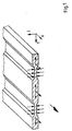
- ein Band mit zwei dünneren Streifen in isometrischer Darstellung und im Schnitt,
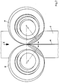
Figur 2- ein Band mit zwei aneinanderstoßenden ausgedünnten Streifen mit zwei Arbeitswalzen in Aufsicht,
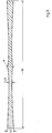
Figur 3- das Band gemäß
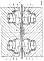
Figur 2 im Querschnitt, Figur 4- eine Vorrichtung zum Herstellen eines Bandes mit zwei ausgedünnten Bereichen im Querschnitt in einer ersten Ausführung,
Figur 5- die Vorrichtung zum Herstellen eines
Metallbandes mit zwei ausgedünnten Bereichen im
Querschnitt in einer zweiten Ausführung
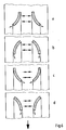
und Figur 6- verschiedene Eingriffsbereiche bei
unterschiedlicher Anstellung der Arbeitswalzen
der
Figuren
- Figure 1
- a tape with two thinner stripes in isometric view and in section,
- Figure 2
- a belt with two abutting, thinned strips with two work rolls in supervision,
- Figure 3
- the tape according to Figure 2 in cross section,
- Figure 4
- a device for producing a band with two thinned areas in cross section in a first embodiment,
- Figure 5
- the device for producing a metal strip with two thinned areas in cross section in a second embodiment
and - Figure 6
- different areas of engagement with different employment of the work rolls of Figures 2,4 and 5 on a belt.
Die Vorrichtungen gemäß den Figuren 4 und 5 sind zum
Herstellen eines Metallbandes mit zwei im Abstand
voneinander angeordneten verdünnten Streifen bestimmt.
Dazu weist jede Vorrichtung jeweils zwei Paar einen
Ziehspalt 1,2 zwischen sich bildender Arbeitswalzen
3,4,5,6 auf. Der Eingriffsbereich dieser Arbeitswalzen
3,4,5,6 befindet sich an deren Stirnseite und wird von
Kegelringflächen 3a,4a,5a,6a gebildet. Die Arbeitswalzen
3,4,5,6 setzen sich aus einzelnen Abschnitten in
Achsrichtung abnehmenden Durchmessers zusammen, und zwar
insbesondere aus kegelstumpfförmigen Abschnitten. Die
Arbeitswalzen 3,4,5,6 sind in einem Gestell 7,8 mittels
Radial- und Axiallager frei drehbar gelagert. Während sie
beim Ausführungsbeispiel der Figur 4 nur im Gestell 7,8
abgestützt sind, sind sie beim Ausführungsbeispiel der
Figur 5 zusätzlich an mitlaufenden Ringen 9,10,12,13
abgestützt, die aufeinander und auf jeweils einem
gestellfesten zylindrischen Lagersitz 11,14 frei drehbar
gelagert sind. Eine Formwalze 15 zwischen den oberen
Arbeitswalzen 3,4 ist entweder im Gestell (Figur 4) oder
auf dem oberen äußeren Stützring 12 frei drehbar
gelagert. The devices according to Figures 4 and 5 are for
Making a metal band with two in the distance
thinned strips arranged from each other.
For this purpose, each device has two pairs each
Beiden Ausführungsbeispielen ist gemeinsam, daß die
Arbeitswalzen mit ihren Drehachsen 3b,4b,5b,6b zweifach
gekippt sind, und zwar zum einen aufeinander zu und zum
anderen in Zugrichtung des Bandes B.Both exemplary embodiments have in common that the
Work rolls with their axes of
Wird nun ein Band, dessen Dicke größer ist als die lichte
Höhe der Ziehspalte 1,2 durch die Vorrichtung der Figur 4
oder 5 gezogen, dann erhält man ein Band, wie es in Figur
1 dargestellt ist. Dabei üben die Arbeitswalzen 3,4,5,6
mit ihren stirnseitigen Kegelringen 3a,4a,5a,6a in den
auszudünnenden Bereichen eine Walzkraft w aus. Die
Eingriffsbereiche sind in Figur 6 dargestellt. Bei frei
drehbar gelagerten Arbeitswalzen 3,4,5,6 werden sie beim
Durchzug des Bandes mitgeschleppt und üben auf das Band
einen Zug quer zur Zugrichtung aus, der dazu führt, daß
das Material in den auszudünnenden Bereichen praktisch
nur quer zur Bandlängsachse fließt. Dieser Effekt des
Fließens des Materials, praktisch nur quer zur
Zugrichtung, läßt sich auch mit anderen Anstellungen der
Arbeitswalzen erreichen, wie sie in Figur 6b,c und d
dargestellt sind. Der Unterschied hierbei ist nur der,
daß bei der Anstellung gemäß Figur 6a und b zwischen den
auszudünnenden Bereichen Zugspannung herrscht, während
bei der Anstellung gemäß Figur 6c und d zwischen den
auszudünnenden Bereichen Druckspannung besteht.Now becomes a band whose thickness is greater than the light one
Height of the
Da beim Durchziehen des Bandes B durch die Ziehspalte 1,2
das Band insgesamt gebreitet wird, bildet sich an den
Bandrändern neben den Arbeitswalzen 3,4,5 eine Welle, die
Spannungen in das Band einleitet. Diesem Effekt wird bei
den Ausführungsbeispielen der Figuren 4 und 5 dadurch
entgegengewirkt, daß mittels der Formwalze 15 in das Band
B vorübergehend eine Sicke eingeformt wird. Diese Sicke
kompensiert die sich sonst an den Bandrändern auswirkende
Breitung. As the tape B is pulled through the
Das Ausführungsbeispiel der Figur 2 unterscheidet sich von denen der Figuren 4 und 5 nur dadurch, daß die Arbeitswalzen 17,18 unmittelbar nebeneinander angeordnet sind. Sie können dann aufeinander abwälzen und sich somit aneinander abstützen. Beim Einsatz derart angestellter Arbeitswalzen 17,18 entsteht ein Band, wie es im Querschnitt in Figur 3 dargestellt ist. Der bei diesem Band leicht erhöhte Mittenbereich M kann in einem nachfolgenden Walzvorgang eingeebnet werden. Soll zur Kompensierung der Breitung vorübergehend eine Sicke in das Band B geformt werden, so kann dies in vorteilhafter Weise mittels eines hier nicht dargestellten Gleitschuhs erfolgen, welcher in dem freien Zwickelbereich zwischen den Arbeitswalzen 17,18 angeordnet wird.The embodiment of Figure 2 differs of those of Figures 4 and 5 only in that the Work rolls 17, 18 arranged directly next to each other are. You can then roll on each other and thus yourself support each other. When using such employees Work rolls 17, 18 creates a band, as in Cross section is shown in Figure 3. The one at this Band slightly increased center area M can be in one subsequent rolling process can be leveled. Should for Compensating for the spread temporarily a bead in the band B can be shaped, this can be advantageous Way by means of a slide shoe, not shown here take place, which in the free gusset area between the work rolls 17, 18 is arranged.
Claims (12)
dadurch gekennzeichnet, daß parallel zu dem Streifen geringerer Dicke gleichzeitig ein weiterer Streifen durch Ziehen des Bandes (B) durch einen dem ersten Ziehspalt spiegelbildlich entsprechenden zweiten Ziehspalt eingeformt wird, wobei die dabei auf das Band ausgeübten Kräfte quer zur Bandlängsrichtung einander kompensieren.Method according to claim 1,
characterized in that, parallel to the strip of reduced thickness, a further strip is simultaneously formed by pulling the band (B) through a second drawing gap corresponding to the first drawing gap, the forces exerted on the band compensating one another transversely to the longitudinal direction of the band.
dadurch gekennzeichnet, daß als Stützwalze eine weitere Arbeitswalze verwendet wird, so daß von beiden Seiten des Bandes (B) mit gleichartigen, zur Bandebene geneigt angestellten Arbeitswalzen umformend auf das Band (B) eingewirkt wird. The method of claim 1 or 2,
characterized in that a further work roll is used as the back-up roll, so that from both sides of the belt (B) with similar work rolls inclined to the belt plane, the belt (B) is reshaped.
dadurch gekennzeichnet, daß bei zwei eine Breitung des Bandes zwischen sich bewirkenden Ziehspalten zwischen den Ziehspalten eine diese Breitung kompensierende Sicke (S) eingeformt wird.The method of claim 1 or 2,
characterized in that, in the case of two spreading of the strip between pulling gaps, a bead (S) compensating for this spreading is formed between the drawing gaps.
dadurch gekennzeichnet, daß als Stützwalze eine weitere Arbeitswalze (4,5) vorgesehen ist, so daß jeder Ziehspalt (1,2) von jeweils zwei gleichartigen, zur Bandebene geneigt angestellten Arbeitswalzen (3,4,5,6) gebildet wird.Device according to claim 5,
characterized in that a further work roll (4, 5) is provided as the back-up roll, so that each drawing nip (1, 2) is formed by two work rolls (3, 4, 5, 6) of the same type, inclined to the strip plane.
dadurch gekennzeichnet, daß die Achsen der Arbeitswalzen sowohl um eine Achse parallel zur Bandlängsachse als auch um eine parallel zur Bandebene und senkrecht zur Bandlängsachse verlaufende Achse gekippt sind. Device according to one of claims 5 or 6,
characterized in that the axes of the work rolls are tilted both about an axis parallel to the longitudinal belt axis and also about an axis running parallel to the belt plane and perpendicular to the longitudinal belt axis.
dadurch gekennzeichnet, daß die Arbeitswalzen (3,4,5,6) sich mit ihren Mänteln unmittelbar oder mittelbar über Laufringe (9,10,12,13) aneinander abstützen.Device according to claim 7,
characterized in that the work rolls (3, 4, 5, 6) are supported directly or indirectly with one another via races (9, 10, 12, 13).
dadurch gekennzeichnet, daß bei mittelbarer Abstützung der Arbeitswalzen (3,4,5,6) zwischen den Ziehspalten (1,2) auf einer Bandseite eine Formwalze (15) zum Einformen einer Sicke (S) vorgesehen ist.Device according to claim 8,
characterized in that with indirect support of the work rolls (3, 4, 5, 6) between the drawing nips (1, 2) a forming roll (15) is provided on a strip side for molding a bead (S).
dadurch gekennzeichnet, daß die Mäntel der Arbeitswalzen (3,4,5,6) kegelig sind.Device according to claim 8 or 9,
characterized in that the jackets of the work rolls (3,4,5,6) are conical.
dadurch gekennzeichnet, daß zur mittelbaren Abstützung der Arbeitswalzen (3,4,5,6) mehrere konzentrisch übereinander angeordnete und unabhängig voneinander drehbare Laufringe (9,10,12,13) die Arbeitswalzen an ihren kegeligen Mänteln abstützen.Apparatus according to claim 10,
characterized in that for the indirect support of the work rolls (3, 4, 5, 6) a plurality of races (9, 10, 12, 13) arranged concentrically one above the other and rotatable independently of one another support the work rolls on their conical shells.
dadurch gekennzeichnet, daß jede Arbeitswalze (3,4,5,6) an ihrer dem Ziehspalt zugeordneten Stirnseite eine Kegelringfläche (3a,4a,5a,6a) als Eingriffsfläche aufweist.Device according to one of claims 6 to 11,
characterized in that each work roll (3, 4, 5, 6) has a conical ring surface (3a, 4a, 5a, 6a) as the engagement surface on its end face assigned to the drawing gap.
Applications Claiming Priority (2)
| Application Number | Priority Date | Filing Date | Title |
|---|---|---|---|
| DE19743093 | 1997-09-30 | ||
| DE19743093A DE19743093C1 (en) | 1997-09-30 | 1997-09-30 | Production of a metal strip with regions of different thickness over its width |
Publications (3)
| Publication Number | Publication Date |
|---|---|
| EP0904865A2 true EP0904865A2 (en) | 1999-03-31 |
| EP0904865A3 EP0904865A3 (en) | 2001-11-14 |
| EP0904865B1 EP0904865B1 (en) | 2004-02-11 |
Family
ID=7844076
Family Applications (1)
| Application Number | Title | Priority Date | Filing Date |
|---|---|---|---|
| EP98118246A Expired - Lifetime EP0904865B1 (en) | 1997-09-30 | 1998-09-25 | Method and apparatus for forming a metal band having areas of different thickness across its width |
Country Status (3)
| Country | Link |
|---|---|
| US (1) | US5953949A (en) |
| EP (1) | EP0904865B1 (en) |
| DE (2) | DE19743093C1 (en) |
Cited By (1)
| Publication number | Priority date | Publication date | Assignee | Title |
|---|---|---|---|---|
| WO2010094538A1 (en) * | 2009-02-19 | 2010-08-26 | Thyssenkrupp Steel Europe Ag | Method for producing a press-quenched metal component |
Families Citing this family (5)
| Publication number | Priority date | Publication date | Assignee | Title |
|---|---|---|---|---|
| US8069407B1 (en) | 1998-12-08 | 2011-11-29 | Yodlee.Com, Inc. | Method and apparatus for detecting changes in websites and reporting results to web developers for navigation template repair purposes |
| DE102007047875A1 (en) * | 2007-11-28 | 2009-06-04 | Hilti Aktiengesellschaft | profile |
| WO2010009751A1 (en) | 2008-07-24 | 2010-01-28 | Welser Profile Ag | Method for production of a profile with at least one thickened profile edge |
| BE1019321A5 (en) | 2010-04-29 | 2012-06-05 | Levin Henri Bvba Ets | TENSION AND BARREL COMPOSITION. |
| FR2973490B1 (en) * | 2011-03-31 | 2018-05-18 | Valeo Systemes Thermiques | THERMAL EXCHANGER TUBE, HEAT EXCHANGER AND CORRESPONDING PROCESSING METHOD |
Family Cites Families (6)
| Publication number | Priority date | Publication date | Assignee | Title |
|---|---|---|---|---|
| IT988066B (en) * | 1971-08-24 | 1975-04-10 | Nippon Steel Corp | STEEL MILL OF THE THREE ROLL TYPE |
| FR2394342A1 (en) * | 1977-06-14 | 1979-01-12 | Mi Radiotekh Inst | Conductive metal strip forming machine - has wire formed between saddle and anvil which are ultrasonically vibrated at different frequencies in inert atmos. |
| FR2515541B1 (en) * | 1981-10-30 | 1985-05-10 | Griset Ets | |
| JPS59109466A (en) * | 1982-12-16 | 1984-06-25 | Nissan Motor Co Ltd | Member for car |
| JPS59202101A (en) * | 1983-05-04 | 1984-11-15 | Nippon Steel Corp | Method for rolling shape material having flange |
| GB9300529D0 (en) * | 1993-01-13 | 1993-03-03 | Penny & Giles Blackwood Ltd | Improvements in rotary forging |
-
1997
- 1997-09-30 DE DE19743093A patent/DE19743093C1/en not_active Expired - Fee Related
-
1998
- 1998-09-25 DE DE59810737T patent/DE59810737D1/en not_active Expired - Fee Related
- 1998-09-25 EP EP98118246A patent/EP0904865B1/en not_active Expired - Lifetime
- 1998-09-25 US US09/160,872 patent/US5953949A/en not_active Expired - Fee Related
Cited By (2)
| Publication number | Priority date | Publication date | Assignee | Title |
|---|---|---|---|---|
| WO2010094538A1 (en) * | 2009-02-19 | 2010-08-26 | Thyssenkrupp Steel Europe Ag | Method for producing a press-quenched metal component |
| CN102317001B (en) * | 2009-02-19 | 2016-02-24 | 蒂森克虏伯钢铁欧洲股份公司 | For the manufacture of the method for the metal parts of press quenching |
Also Published As
| Publication number | Publication date |
|---|---|
| EP0904865A3 (en) | 2001-11-14 |
| EP0904865B1 (en) | 2004-02-11 |
| DE59810737D1 (en) | 2004-03-18 |
| DE19743093C1 (en) | 1998-12-17 |
| US5953949A (en) | 1999-09-21 |
Similar Documents
| Publication | Publication Date | Title |
|---|---|---|
| DE2813636C3 (en) | Process and device for the production of profiles made of metal, primarily steel profiles | |
| DE3873103T2 (en) | METAL ROLLING METHOD WITH WORK ROLLS SLIDING IN THE AXIAL DIRECTION. | |
| DE10041280C2 (en) | Method and device for flexible rolling of a metal strip | |
| DE3885019T2 (en) | Method and device for straightening a metallic strip. | |
| DE1940341B2 (en) | Method and device for producing metal strips, in particular tubular welding electrodes, from a rod material | |
| DE3103530A1 (en) | METHOD FOR INTERLOCKING CALIBERS INTENDED FOR THE DIVING STICK OF A UNIVERSAL ROLLING PROCESS OF PROFILE PIECES, AND ROLLING, ROLLING DEVICES AND ROLLING MACHINES FOR CARRYING OUT THIS METHOD | |
| DE1809638A1 (en) | Device for processing sheet metal or strip material | |
| DE3780453T2 (en) | ROLLER FOR DIVING FLANGES OF A ROLLING PROFILE. | |
| EP0904865B1 (en) | Method and apparatus for forming a metal band having areas of different thickness across its width | |
| DE1919815A1 (en) | Process and device for the continuous rolling of thin strips | |
| DE3417500C2 (en) | ||
| DE1427875B2 (en) | Rolling mill for rolling profiles with thin walls, such as double T-beams or the like | |
| DE2848295C2 (en) | Calender for the production of thermoplastic films | |
| DE102010005758B3 (en) | Apparatus and method for guiding tapes to be joined together along their longitudinal edges | |
| DE69004558T2 (en) | Device for rolling and slitting without twisting and method for producing reinforcing bars. | |
| DE3302333C2 (en) | ||
| EP0264849A2 (en) | Process and arrangement for rolling profiled bars within small tolerances | |
| DE1565740B2 (en) | DEVICE FOR THE CONTINUOUS MANUFACTURING OF LIGHTWEIGHT ASSEMBLED METALLIC I-BEAMS USING AN ELECTRIC RESISTANCE SEAM WELDING DEVICE | |
| DE1779588C3 (en) | Process for the continuous production of elongated foam bodies with a curved outer surface and device for carrying out the process | |
| DE69300944T2 (en) | Method and device for producing individual round rods in the warm state from warm multiple elements. | |
| DE1527630A1 (en) | Caliber rolling mill | |
| DE102022004111B4 (en) | Method for cross rolling of blanks with the axial tensile force acting in the rolling caliber | |
| DE102010048242A1 (en) | Drawing unit for spinning machine, has compressor component that is rested on one axial side or both axial sides of grooved portion of output lower roll | |
| AT286214B (en) | Method and device for treating cast strands by rolling | |
| DE2819567A1 (en) | ROLLING MILL FOR ROLLING BAR-SHAPED METALLIC GOODS |
Legal Events
| Date | Code | Title | Description |
|---|---|---|---|
| PUAI | Public reference made under article 153(3) epc to a published international application that has entered the european phase |
Free format text: ORIGINAL CODE: 0009012 |
|
| AK | Designated contracting states |
Kind code of ref document: A2 Designated state(s): AT BE CH CY DE DK ES FI FR GB GR IE IT LI LU MC NL PT SE Kind code of ref document: A2 Designated state(s): DE FR GB |
|
| AX | Request for extension of the european patent |
Free format text: AL;LT;LV;MK;RO;SI |
|
| PUAL | Search report despatched |
Free format text: ORIGINAL CODE: 0009013 |
|
| AK | Designated contracting states |
Kind code of ref document: A3 Designated state(s): AT BE CH CY DE DK ES FI FR GB GR IE IT LI LU MC NL PT SE |
|
| AX | Request for extension of the european patent |
Free format text: AL;LT;LV;MK;RO;SI |
|
| RIC1 | Information provided on ipc code assigned before grant |
Free format text: 7B 21C 37/02 A, 7B 21C 3/08 B, 7B 21C 37/08 B, 7B 21B 1/08 B, 7B 21H 7/00 B |
|
| 17P | Request for examination filed |
Effective date: 20011207 |
|
| RAP1 | Party data changed (applicant data changed or rights of an application transferred) |
Owner name: THYSSENKRUPP STAHL AG |
|
| AKX | Designation fees paid |
Free format text: DE FR GB |
|
| GRAP | Despatch of communication of intention to grant a patent |
Free format text: ORIGINAL CODE: EPIDOSNIGR1 |
|
| GRAS | Grant fee paid |
Free format text: ORIGINAL CODE: EPIDOSNIGR3 |
|
| GRAA | (expected) grant |
Free format text: ORIGINAL CODE: 0009210 |
|
| AK | Designated contracting states |
Kind code of ref document: B1 Designated state(s): DE FR GB |
|
| REG | Reference to a national code |
Ref country code: GB Ref legal event code: FG4D Free format text: NOT ENGLISH |
|
| GBT | Gb: translation of ep patent filed (gb section 77(6)(a)/1977) |
Effective date: 20040211 |
|
| REF | Corresponds to: |
Ref document number: 59810737 Country of ref document: DE Date of ref document: 20040318 Kind code of ref document: P |
|
| PG25 | Lapsed in a contracting state [announced via postgrant information from national office to epo] |
Ref country code: GB Free format text: LAPSE BECAUSE OF NON-PAYMENT OF DUE FEES Effective date: 20040925 |
|
| ET | Fr: translation filed | ||
| PLBE | No opposition filed within time limit |
Free format text: ORIGINAL CODE: 0009261 |
|
| STAA | Information on the status of an ep patent application or granted ep patent |
Free format text: STATUS: NO OPPOSITION FILED WITHIN TIME LIMIT |
|
| 26N | No opposition filed |
Effective date: 20041112 |
|
| GBPC | Gb: european patent ceased through non-payment of renewal fee |
Effective date: 20040925 |
|
| PG25 | Lapsed in a contracting state [announced via postgrant information from national office to epo] |
Ref country code: FR Free format text: LAPSE BECAUSE OF NON-PAYMENT OF DUE FEES Effective date: 20050531 |
|
| REG | Reference to a national code |
Ref country code: FR Ref legal event code: ST |
|
| PGFP | Annual fee paid to national office [announced via postgrant information from national office to epo] |
Ref country code: DE Payment date: 20061018 Year of fee payment: 9 |
|
| PG25 | Lapsed in a contracting state [announced via postgrant information from national office to epo] |
Ref country code: DE Free format text: LAPSE BECAUSE OF NON-PAYMENT OF DUE FEES Effective date: 20080401 |