EP1415818A1 - Dispositif d'enregistrement d'images par l'expansion d'image en motif des points - Google Patents
Dispositif d'enregistrement d'images par l'expansion d'image en motif des points Download PDFInfo
- Publication number
- EP1415818A1 EP1415818A1 EP03024801A EP03024801A EP1415818A1 EP 1415818 A1 EP1415818 A1 EP 1415818A1 EP 03024801 A EP03024801 A EP 03024801A EP 03024801 A EP03024801 A EP 03024801A EP 1415818 A1 EP1415818 A1 EP 1415818A1
- Authority
- EP
- European Patent Office
- Prior art keywords
- recording
- dot
- pattern
- dots
- recording element
- Prior art date
- Legal status (The legal status is an assumption and is not a legal conclusion. Google has not performed a legal analysis and makes no representation as to the accuracy of the status listed.)
- Granted
Links
Images


Classifications
-
- B—PERFORMING OPERATIONS; TRANSPORTING
- B41—PRINTING; LINING MACHINES; TYPEWRITERS; STAMPS
- B41J—TYPEWRITERS; SELECTIVE PRINTING MECHANISMS, i.e. MECHANISMS PRINTING OTHERWISE THAN FROM A FORME; CORRECTION OF TYPOGRAPHICAL ERRORS
- B41J2/00—Typewriters or selective printing mechanisms characterised by the printing or marking process for which they are designed
- B41J2/005—Typewriters or selective printing mechanisms characterised by the printing or marking process for which they are designed characterised by bringing liquid or particles selectively into contact with a printing material
- B41J2/01—Ink jet
- B41J2/21—Ink jet for multi-colour printing
- B41J2/2121—Ink jet for multi-colour printing characterised by dot size, e.g. combinations of printed dots of different diameter
- B41J2/2125—Ink jet for multi-colour printing characterised by dot size, e.g. combinations of printed dots of different diameter by means of nozzle diameter selection
Definitions
- the present invention relates to an ink-jet recording apparatus, and a recording control method for the ink-jet recording apparatus. More particularly, the present invention relates to a dot-matrix ink-jet recording apparatus that records an image by ejecting ink at a plurality of ejected ink amounts of the same color ink, each value of n-level quantized data (n is equal to or greater than 3) corresponding to a respective ink ejected amount and each value expanded in a matrix of L columns by M rows for each of the plurality of ink amounts of the same color.
- ink of the same color is ejected at a plurality of amounts to form an image to satisfy both a high-definition requirement and a high-speed recording requirement.
- Japanese Patent Laid-Open No. 2002-301815 discloses an ink-jet recording apparatus.
- record data corresponding to a plurality of recording elements different in the size of forming dots is generated, and the generated record data for the plurality of dots different in size is independently converted with respect to one pixel.
- the conversion process here refers to a relatively low resolution and multi-level quantization process that is performed by a host apparatus. Image data subjected to the conversion process is transferred to the recording apparatus.
- the recording apparatus then converts the received low-resolution and multi-level quantized data to a dot pattern of a predetermined matrix.
- the recording apparatus performs a so-called dot-matrix recording by recording the data in the dot pattern.
- a plurality of dot matrices different in dot pattern are prepared beforehand, and a dot matrix is selected from among the plurality of dot matrices according to a random number having a predetermined number of bits, and is then assigned to the record data.
- the presence or absence of data in a raster is identified, and the dot patterns are successively switched.
- the dot patterns assigned to each of the plurality of dots different in size cause the following problem depending on the layout of the dot patterns.
- An error in the landing of ink droplets, the sheet conveyance in the recording apparatus, and the scanning of a carriage may cause periodic density non-uniformities and streaks on an actual image in which the same tonal gradation continuously extends.
- the periodic non-uniformities and streaks are closely related to a dot coverage ratio per unit pixel, namely, a so-called area factor per unit pixel. If dots different in size are placed in the same pixel in an overlapping manner with an image output in an intermediate gradation region, the area factor gets smaller than in the case where the dots are separately placed, and the density non-uniformities and streaks become pronounced.
- dots different in size or different in color may be placed in an overlapping position along the same path.
- a recording medium fails to fully absorb ink in a localized area. The dot is deformed in shape, thereby becoming a noise-like image not preferable in the image formation.
- an object of the present invention to provide an ink-jet recording apparatus that records a high-definition image free from density non-uniformities, streaks, and deformation of a dot shape when a plurality of dots different in size are used to record the image.
- An ink-jet recording apparatus of the present invention records an image on a recording medium using a recording head having a plurality of recording elements that result in dots different in size.
- the ink-jet recording apparatus quantizes the record data in n level-quantization (n is equal to or larger than 3) at a predetermined resolution so that the sizes of the dots formed by the recording head correspond to the plurality of recording elements, assigns the quantized input image data to a dot matrix, and ejects ink in a dot pattern of the assigned dot matrix.
- the ink-jet recording apparatus includes a matrix storage unit that stores beforehand a plurality of dot matrices different in dot pattern in response to input image data at the same signal level, a dot pattern setting unit that independently sets the dot pattern stored in the dot matrix storage unit to each of the plurality of recording elements that form dots different in size, and a dot matrix assignment unit that selects and assigns a dot matrix corresponding to a signal level of the input image data from the plurality of dot matrices stored in the matrix storage unit, and expands the dot pattern of the assigned dot matrix in a buffer.
- the input image data may be color image data, and the dot pattern setting unit sets the dot matrix independently on a color by color basis.
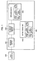
- Fig. 1 is a block diagram of a recording controller of an ink-jet recording apparatus implementing the present invention.
- Fig. 2 is a flow diagram illustrating a data expansion process in accordance with a first preferred embodiment of the present invention.
- Fig. 3 illustrates an image signal value subsequent to and prior to a color conversion in accordance with the first preferred embodiment of the present invention.
- Fig. 4 illustrates a pattern of a dot matrix at each level for use in the recording apparatus.
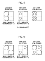
- Figs. 5A through 5C illustrate recording positions of a large dot and a small dot in the matrix.
- Figs. 6A through 6C illustrate recording positions of a large dot and a small dot in the matrix.
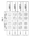
- Fig. 7 illustrates dot patterns in which a dot matrix is arranged on a per dot size basis.
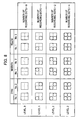
- Fig. 8 illustrates a dot pattern in which a dot matrix is assigned to each color.
- Fig. 9 illustrates a major portion of an ink-jet recording apparatus implementing the present invention.
- Fig. 10 is a block diagram illustrating the controller of the recording apparatus.
- Fig. 11 diagrammatically illustrates a major portion of a recording head used in the ink-jet recording apparatus implementing the present invention.
- An ink-jet recording apparatus of the present invention records an image on a recording medium using a recording head having a plurality of recording elements that result in dots different in size.
- the ink-jet recording apparatus quantizes the record data in an n level quantization (n is equal to or larger than 3) at a predetermined resolution so that the sizes of the dots formed by the recording head correspond to the plurality of recording elements.
- n is equal to or larger than 3
- the quantized data is assigned to a dot matrix of L columns and M rows
- one dot matrix pattern is selected from a plurality of dot matrices having different patterns and is assigned to the quantized data at the same signal level, namely, the image data at the same level subsequent to the quantization.
- the dot patterns of the dot matrices corresponding to the record data of a plurality of recording elements presenting dots different in size are arranged so that large and small dots are separately located in a manner such that the dots different in size in low and intermediate level regions are not overlapped on each other.
- the use of the assigned dot pattern for image recording controls density non-uniformities and streaks generated in an intermediate gradation region, in particular, in a recorded image, subject to projection performance and mechanical accuracy of the recording head of the ink-jet recording apparatus having a relatively high resolution.
- the dots different in size in the low to intermediate gradation regions are not formed in an overlapping position along the same path.
- This arrangement controls the deformation of the dot attributed to localized ink run on a recording medium, thereby reducing noisiness in the recorded image.
- dot patterns are independently set for yellow (Y), magenta (M), and cyan (C).
- the dots are arranged in the dot matrix pattern.
- dots of the patterns used in the low to intermediate gradation region are separately located. In this arrangement, noisiness is reduced in a secondary color (blue) having a low lightness and a high visibility.
- FIG. 9 illustrates a major portion of the ink-jet recording apparatus.
- the ink-jet printing apparatus (the recording apparatus) employs a head cartridge as recording means.
- a head cartridge 1 is detachably mounted on a carriage 2.
- the head cartridge 1 includes a print head and an ink tank.
- the head has a connector (not shown) to exchange signals for driving the print head.
- the head cartridge 1 is detachably mounted on and aligned with the carriage 2.
- the carriage 2 has a connector holder (for electrical connection) that holds the connector through which a drive signal, etc., is transferred to the head cartridge 1.
- the carriage 2 is supported by guide shafts 3 in a manner such that the carriage 2 is reciprocated along the guide shafts 3.
- the guide shafts 3 extend in a main scan direction of the head cartridge 1 and are secured to the body of the recording apparatus.
- the carriage 2 is driven by a driving mechanism including a motor pulley 5, a driven pulley 6, and a timing belt 7.
- the driving mechanism is drive by a main scan motor 4.
- the carriage 2 is thus controlled in position and movement by the main scan motor 4.
- a home position sensor 30 is disposed on the carriage 2. The position of the carriage 2 is thus known at the moment the home position sensor 30 of the carriage 2 passes by a blocking plate 36.
- Printing media 8 such as a printing sheet or plastic thin film, are detached and fed from an automatic sheet feeder (ASF) 32 one by one when a sheet feeder motor 35 rotates pickup rollers 31 through gears.
- ASF automatic sheet feeder
- the conveyance rollers 9 With conveyance rollers 9 rotating, the printing medium 8 is conveyed in a sub scan direction and passes by a printing position facing an ejection port surface of the head cartridge 1.
- the conveyance rollers 9 are driven through gears, which are driven by an LF motor 34 through gears.
- the determination of whether or not a sheet is fed and the detection of a leading edge of the sheet are performed at the moment the printing medium 8 passes by a paper end sensor 33.
- the paper end sensor 33 is also used to locate the trailing edge of the printing medium 8 and to detect a current recording position ahead of the trailing edge.
- the printing medium 8 is supported from below by a platen (not shown) to form a flat printing surface in a printing position.
- the head cartridge 1 mounted on the carriage 2 has the ejection port surface projected downward and is supported between two pairs of conveyance rollers so that the ejection port surface is parallel to the printing medium 8.
- the head cartridge 1 is an ink-jet head cartridge that ejects ink using thermal energy, and has an electrical to thermal energy converting unit for generating thermal energy. Using pressure of a bubble caused by film boiling resulting from the thermal energy, a print head of the head cartridge 1 ejects ink through an ejection port thereof. Any other ink ejection method is acceptable. For example, a piezoelectric element may be used to eject ink.
- the controller includes an interface 400 for inputting a record signal, an MPU 401, a program ROM 402 for storing a control program to be executed by the MPU 401, a dynamic RAM (DRAM) 403 for storing a variety of data including the record signal, record data fed to the head, the number of print dots, and the number of replacements of the recording head.
- a gate array 404 controls the supply of the record data to a recording head 410, and also controls the transfer of data to the interface 400, the MPU 401, and the DRAM 403.
- a carriage motor 406 moves the recording head, and a conveyance motor 405 conveys a recording sheet. Motor drivers 408 and 407 drive the carriage motor 405 and the conveyance motor 406, respectively.
- a head driver 409 drives the recording head 410.
- the recording head 1 will now be discussed with reference to Fig. 11.
- Fig. 11 diagrammatically illustrates a first structure of a major portion of the recording head 1 of the head cartridge 2.
- a first recording head 100 for a large cyan dot is referred to as 100C1.
- a first recording head 101 for a small cyan dot is referred to as 101SC1.
- a first recording head 102 for a large magenta dot is referred to as 102M1.
- a first recording head 103 for a small magenta dot is referred to as 103SM1.
- a first recording head 104 for a large yellow dot is referred to as 104Y1.
- a second recording head 105 for a large yellow droplet is referred to as 105Y2.
- a second recording head 106 for a small magenta dot is referred to as 106SM2.
- a second recording head 107 for a large magenta dot is referred to as 107M2.
- a second recording head 108 for a small cyan dot is referred to as 108SC2.
- a second recording head 109 for a large cyan dot is referred to as 109C2.
- a pair of recording heads forming the same color pixel are shifted from each other by half the nozzle pitch in the direction of sub scan. This shifting is intended to reduce dot overlapping to achieve the maximum density and to increase the dot coverage ratio.
- a black (Bk) recording head may be additionally used.
- each recording head contains a plurality of ejection nozzles.
- the recording head 100C1 contains cyan ink ejecting nozzles 110
- the recording head 101SC1 contains small cyan ejecting nozzles 111.
- the nozzle group in each recording head is arranged in a line generally perpendicular to the main scan direction. Occasionally, the nozzle group may be arranged in a line slightly slant to the main scan direction, rather than being perpendicular to the main scan direction, in relation to an ink ejection timing. Alternatively, the nozzle group may be aligned in parallel with the main scan direction. Specifically, the recording heads 100C1, 101SC1, 102M1, 103SM1, 104Y1, 105Y2, 106SM2, 107M2, 108SC2, and 109C are arranged in parallel with the main scan direction.
- an ink-jet recording apparatus of the present invention records an image on a recording medium using a recording head having a plurality of recording elements that result in dots different in size.
- the ink-jet recording apparatus quantizes the record data in n level quantization (n is equal to or larger than 3) at a predetermined resolution so that the sizes of the dots formed by the recording head correspond to the plurality of recording elements.
- n is equal to or larger than 3
- one dot matrix pattern is selected from a plurality of dot matrices having different patterns and is assigned to the quantized data at the same signal level, namely, the image data at the same level subsequent to the quantization.
- the dot matrices of L columns by M rows are stored beforehand with the record data, of the plurality of recording elements resulting in dots different in size, associated with the dot matrices of L columns by M rows.
- the ink-jet recording apparatus of the first preferred embodiment has the above-referenced structure of the recording apparatus.
- Fig. 1 is a block diagram illustrating a recording controller 500 of the ink-jet recording apparatus in accordance with the first preferred embodiment of the present invention.
- the recording controller 500 of the ink-jet recording apparatus includes a receiving buffer 1001 for receiving quantized data from a host apparatus 1000, a matrix storage unit 1002 for storing a matrix pattern, a dot matrix assigning module 1003 for assigning a dot matrix to the quantized data in the receiving buffer 1001 using the matrix pattern, and an expansion buffer (print buffer) 1004 for expanding the quantized data (data corresponding to record data that is assigned to the dot matrix subsequent to the quantization) which is expanded using the dot matrix assigned by the dot matrix assigning module 1003.
- the recording controller 500 contains memories, such as a ROM and a DRAM, and an MPU performing a process. In comparison with the structure shown in Fig.
- the dot matrix assigning module 1003 corresponds to a software module stored beforehand in the program ROM 402 and executed by the MPU 401.
- the receiving buffer 1001, the matrix storage unit 1002, and the expansion buffer 1004 correspond to the DRAM 403.
- the quantized data is stored at a predetermined address in the DRAM 403.
- the matrix storage unit 1002 stores beforehand the pattern of the dot matrix that can be taken by the quantized data at each of signal levels, level 0 to level 3, for each of the dots different in size.
- the pattern is numbered before being stored.
- One of a plurality of dot matrix patterns stored in the matrix storage unit 1002 is selected, and the selected pattern is then expanded onto the expansion buffer 1004. This process will be discussed with reference to the drawings.
- image data which is quantized to four levels (2 bits) at a resolution of 600 columns by 600 rows DPI by the host apparatus 1000, is expanded to print data at a resolution of 1200 columns by 1200 rows DPI (2x2 dot matrix) in the ink-jet recording apparatus.
- the print data expanded according to the unit of dot refers to data stored in the expansion buffer 1004.
- Fig. 2 is a flow diagram illustrating a data expansion process performed by the dot matrix assigning module 1003 in accordance with the first preferred embodiment of the present invention.
- step S1 the recording controller 500 receives 2 bit data (4 levels corresponding to 0 through 3) transferred from the host apparatus 1000.
- the received data is stored in the receiving buffer 1001.
- step S2 2 bit quantized data for one pixel is read.
- the number of patterns of quantized data at the same signal level is two.
- step S3 one of the dot matrix patterns corresponding to the quantized data for the one pixel read in step S2 is selected.
- the dot matrix pattern is expanded onto the expansion buffer 1004. When the dot matrix pattern is selected, the two patterns at the same level are alternately assigned referencing the presence or absence of data in the raster.
- step S4 it is then determined in step S4 whether the image data of all pixels stored in the receiving buffer 1001 in step S1 is expanded onto the expansion buffer 1004. If pixels remain unexpanded (no answer to the determination in step S4), the algorithm loops to step S2. If the answer to the determination in step S4 is yes, the data expansion process ends.
- Fig. 3 plots image signal values prior to and subsequent to a color conversion process performed in the host apparatus in order that the recording apparatus records data on the recording medium using a recording head having a plurality of recording elements resulting in dots different in size.
- Input signals for cyan ink ejection ranging from zero to 255 are plotted along the abscissa and output signal values subsequent to the conversion process are plotted along the ordinate.
- the graph in Fig. 3 presents a profile of a small cyan (small ejected amount of cyan ink) and a large cyan (large ejected amount of cyan ink).
- the image output values 0/255, 85/255, 170/255, and 255/255 are referred to as level 0, level 1, level 2, and level 3.
- the dot matrix, from a plurality of dot patterns, corresponding to the level is assigned. More specifically, level 0 through level 3 are set to the outputs of a large dot and a small dot responsive to the input value in a particular color (cyan in Fig. 3) to assign the dot matrix to the level of the output value.
- the known error distribution method may be used.
- the image data is quantized into 4 values.
- the upper limit of the level of the small dot is 2, and the input values 0 through 255 are converted into outputs of the large dot and the small dot.
- one dot matrix may be selected from among a plurality of dot matrices based on a random number having a predetermined bit numbers, or the dot patterns may be successively selectively switched by detecting the presence or absence of data in the raster.
- Fig. 4 illustrates a known dot matrix pattern, which is commonly used. As shown, numbers 1 through 4 are assigned to dot matrix patterns the quantized data can take at each of the level 0 through the level 3. These dot matrix patterns are stored beforehand in the ROM, for example. For convenience of explanation, a maximum of four patterns are stored for the quantized data at a given level. The present invention is not limited to the four patterns. The number of patterns is preferably optimized taking into consideration the structure of the recording apparatus. If the number of different dot matrix patterns is not more than four, the same pattern may be used.
- the small cyan dots and the large cyan dots coexist to form an image in an intermediate input gradation region from 200 to 255.
- An image in which the same gradation level extends, is formed of the dot matrix of the large cyan dots at level 2 and the dot matrix of the small cyan dots at level 2 if the dot matrices shown in Fig. 4 are used.
- the large cyan dots and the small cyan dots overlap each other as shown in Fig. 5C. If an image is formed in such a pattern combination, the area factor thereof becomes smaller than in the combination where the large cyan dot and the small cyan dot are placed at different positions, namely, spaced apart. Density non-uniformities and streaks may be generated in a recorded image depending on the projection performance and mechanical precision of the recording head.
- the dot pattern of the small cyan dots and the dot pattern of the large cyan dots are arranged in complementary positions as shown in Figs. 6A-6C.
- the large dots and the small dots are thus recorded in different positions.
- the area factor is increased, and image recording is performed in a dot layout that is preferred in view of image quality.
- the dot matrix pattern of the present invention controls more the density non-uniformities and streaks than the known pattern shown in Fig. 4. High image quality recording is thus achieved.
- the large cyan dot and the small cyan dot may be presented along the same path in principle using a recording cartridge having horizontally aligned heads, namely, a plurality of recording heads aligned in the main scan direction thereof. If the large cyan dot and the small cyan do not overlap in position, a large amount of ink is localized, running on a recording sheet. The dot shape is deformed, causing the resulting image to look like noise to the eyes of the user.
- the dot matrix is changed according to the size of the dot and the dots different in size are spaced apart from each other.
- the feature of the first preferred embodiment of the present invention is that the dot matrix is changed for different dot size and that the dot patterns are independently set.
- Fig. 7 illustrates an example of dot patterns in which the dot matrix is arranged according to size of the dot.
- Numbers 1 and 2 are assigned to the patterns the quantized data can take at each of the signal levels 0 through 3 before the quantized data is stored.
- a maximum of two patterns are assigned to the quantized data at a given level, and the patterns of dots different in size complement each other.
- the dots different in size are always separated.
- the dot patterns illustrated in Fig. 7 have the feature that, at each of n levels (n is 0, 1, 2, or 3) except the highest level, the dots in the large dot pattern and the dots in the small dot pattern at least at the same level are not placed at the same recording positions. In such an arrangement, the problem that has already discussed with reference to Figs. 5A-5C is avoided.
- the dot recording positions are different between the large dot pattern and the small dot pattern at least at the same level. In this arrangement, even if the pattern of large dots and the pattern of small dots at the same level are overlapped on each other, no dots overlap each other on the recording medium. The area factor is heightened, and the conventional problem is thus controlled.
- the large dots and the small dots do not overlap each other even if the large dot pattern and the small dot pattern are recorded on the same pixel.
- the dot pattern is formed so that the large dot and the small dot do not overlap in a resulting pattern.
- the large dots and the small dots are not overlapped on each other and separately recorded in a plurality of dot positions in the same pixel from low to intermediate gradation regions.
- the recording apparatus thus overcomes the drawback of the conventional art, and records a high-quality image.
- the dot patterns of the large cyan dots and the small cyan dots are the same, and the dots different in size are overlapped on each other.
- the level 3 signals provides a high recording density, presenting a satisfactory area factor. There is no possibility that the density non-uniformities and streaks occur in the recorded image.
- the small dots are not used at level 3 because the image recording is performed in accordance with the profile illustrated in Fig. 3.
- the recording head with the recording elements symmetrically arranged in color is employed, whether to record data on a pixel on in the raster is preferably determined, one of number 1 pattern and number 2 pattern shown in Fig. 7 is successively selected, and the selected pattern is assigned to each pixel. In this arrangement, the frequency of use of each recording element in the recording head is distributed.
- the recording head includes, at least, the first recording element and the second recording element corresponding to the large dot and the small dot, respectively.
- the use of the dot pattern corresponding to the first recording element and the dot pattern corresponding to the second recording element prevents the dot recorded by the first recording element and the dot recorded by the second recording element from overlapping each other. This arrangement overcomes the drawback of the conventional art. Second Preferred Embodiment
- the recording apparatus of the second preferred embodiment is also constructed as already discussed with reference to Figs. 9 and 10, and the recording head of the recording apparatus is also constructed as already discussed with reference to Fig. 11. The detail of the structure of the recording apparatus is not discussed again here.
- the dot matrix patterns are selected on a color by color basis (Y, M, and C).
- the dot matrix pattern is set and assigned to the recording image of each color. This is different from the first preferred embodiment of the present invention. From among a plurality of colors (Y, M, and C), the dots in the dot patterns of magenta (M) and cyan (C), having a low lightness and a high visibility, used in low to intermediate gradation regions are separately placed. noisysy image is thus reduced in a secondary color (blue) having a low lightness and a high visibility. Ink-jet printers typically use black ink, but black ink is separately used in many cases.
- the colors, which are particularly separated from among the colors of Y, M, and C except Bk are two colors, namely, magenta (M) and cyan (C).
- Fig. 8 illustrates an example of dot patterns in the second preferred embodiment, in which cyan (C), magenta (M), and yellow (Y) dot matrices are independently assigned.
- the cyan and magenta patterns having a low lightness, are arranged in mutually non-overlapping positions.
- a yellow pattern naturally overlaps the other colors, and is arranged to overlap equally cyan and magenta patterns.
- the data expansion process performed by the dot matrix assigning module 1003 is substantially identical to the data expansion process in the first preferred embodiment.
- the main difference between the first and second preferred embodiments is that the data expansion process is performed on yellow, magenta, and cyan on a color by color basis.
- the dot matrix patters are independently set on the colors of yellow, magenta, and cyan on a color by color basis.
- a dot pattern is selected from the plurality of dot patterns at the same level.
- the dots of the selected pattern are expanded in the expansion buffer 1004. In this way, the dots in the pattern of the recording image used in low to intermediate gradation regions are separately arranged. noisysiness of image in the secondary color (blue) having a low lightness and a high visibility is thus reduced.
- the recording head includes, at least, the first recording element and the second recording element corresponding to cyan and magenta.
- the use of the dot pattern corresponding to the first recording element and the dot pattern corresponding to the second recording element prevents the dot recorded by the first recording element and the dot recorded by the second recording element from overlapping each other. This arrangement overcomes the drawback of the conventional art.
- the patterns of small dots of each color may be arranged as illustrated in Fig. 7.
- the large dot and the small dot of the same color are separately recorded, but the large dot and the small dot different in color are overlapped on each other in recording.
- This arrangement overcomes the problem that the density non-uniformities and streaks appears in low to intermediate gradation regions in a particular color, and reduces noisiness in the secondary color in which substantially equal amounts of cyan and magenta inks are used.
- the present invention thus achieves improved image quality.
- the recording head having the first and second recording elements corresponding to, at least, the large dot and the small dot is used, or the recording head having the first and second recording elements corresponding to different colors is used.
- the record data of n levels (n is an integer equal to or larger than 3) is expanded in a dot pattern at each of the n levels.
Landscapes
- Ink Jet (AREA)
- Particle Formation And Scattering Control In Inkjet Printers (AREA)
Applications Claiming Priority (2)
| Application Number | Priority Date | Filing Date | Title |
|---|---|---|---|
| JP2002317805A JP2004148723A (ja) | 2002-10-31 | 2002-10-31 | 記録装置 |
| JP2002317805 | 2002-10-31 |
Publications (2)
| Publication Number | Publication Date |
|---|---|
| EP1415818A1 true EP1415818A1 (fr) | 2004-05-06 |
| EP1415818B1 EP1415818B1 (fr) | 2008-06-04 |
Family
ID=32089579
Family Applications (1)
| Application Number | Title | Priority Date | Filing Date |
|---|---|---|---|
| EP03024801A Expired - Fee Related EP1415818B1 (fr) | 2002-10-31 | 2003-10-30 | Dispositif d'enregistrement d'images par l'expansion d'image en motif des points |
Country Status (5)
| Country | Link |
|---|---|
| US (1) | US6846066B2 (fr) |
| EP (1) | EP1415818B1 (fr) |
| JP (1) | JP2004148723A (fr) |
| CN (1) | CN1262928C (fr) |
| DE (1) | DE60321436D1 (fr) |
Cited By (1)
| Publication number | Priority date | Publication date | Assignee | Title |
|---|---|---|---|---|
| EP1898340A3 (fr) * | 2006-08-07 | 2008-12-03 | Canon Kabushiki Kaisha | Tête d'enregistrement à jet d'encre |
Families Citing this family (22)
| Publication number | Priority date | Publication date | Assignee | Title |
|---|---|---|---|---|
| JP2005169736A (ja) * | 2003-12-09 | 2005-06-30 | Brother Ind Ltd | インクジェット記録装置及びインクジェット記録方法 |
| JP2005169754A (ja) * | 2003-12-09 | 2005-06-30 | Canon Inc | インクジェット記録装置及びインクジェット記録方法 |
| JP4375235B2 (ja) * | 2004-05-20 | 2009-12-02 | セイコーエプソン株式会社 | 複数画素ずつコード化しながら画像を出力する画像出力システム |
| JP4125271B2 (ja) * | 2004-08-18 | 2008-07-30 | キヤノン株式会社 | データ処理装置、データ処理方法、インクジェット記録装置、インクジェット記録方法、およびプログラム |
| US7770997B2 (en) * | 2004-09-27 | 2010-08-10 | Hewlett-Packard Development Company, L.P. | Printhead die warming |
| JP5049465B2 (ja) * | 2005-02-21 | 2012-10-17 | キヤノン株式会社 | 記録装置及び記録ヘッド |
| US7618116B2 (en) * | 2005-12-14 | 2009-11-17 | Canon Kabushiki Kaisha | Printing apparatus and method for alternately performing preliminary discharge control of nozzles |
| JP4863482B2 (ja) * | 2005-12-14 | 2012-01-25 | キヤノン株式会社 | 記録装置及びその制御方法、記録ヘッドの制御回路及び記録ヘッドの駆動方法 |
| JP4743418B2 (ja) | 2006-03-03 | 2011-08-10 | 富士フイルム株式会社 | 画像形成装置及び画像形成方法 |
| JP4800803B2 (ja) | 2006-03-08 | 2011-10-26 | 富士フイルム株式会社 | 画像形成装置及び画像形成方法 |
| JP4850626B2 (ja) | 2006-08-23 | 2012-01-11 | キヤノン株式会社 | 画像記録装置および画像記録方法 |
| JP4827674B2 (ja) * | 2006-09-22 | 2011-11-30 | 富士フイルム株式会社 | 記録装置及び記録方法 |
| US20090015612A1 (en) | 2007-07-10 | 2009-01-15 | Canon Kabushiki Kaisha | Ink jet printing apparatus and ink jet printing method |
| US8253980B2 (en) | 2007-08-20 | 2012-08-28 | Canon Kabushiki Kaisha | Data processing device, ink jet printing system and data processing method |
| KR101510758B1 (ko) * | 2008-12-05 | 2015-04-10 | 삼성전자 주식회사 | 디스플레이장치 및 그의 사용자 인터페이스 표시방법 |
| JP2010228286A (ja) * | 2009-03-27 | 2010-10-14 | Brother Ind Ltd | 印刷制御装置、ラインヘッド型の印刷装置、およびドットサイズ決定方法 |
| JP5448528B2 (ja) * | 2009-03-31 | 2014-03-19 | キヤノン株式会社 | 記録装置及び記録方法 |
| EP2287002B1 (fr) * | 2009-08-11 | 2012-11-28 | Canon Kabushiki Kaisha | Appareil d'impression et procédé d'impression |
| JP5661366B2 (ja) | 2010-07-30 | 2015-01-28 | キヤノン株式会社 | 画像処理装置および画像処理方法 |
| JP5995642B2 (ja) | 2012-10-11 | 2016-09-21 | キヤノン株式会社 | 記録装置および記録方法 |
| JP6203025B2 (ja) | 2013-12-10 | 2017-09-27 | キヤノン株式会社 | 記録装置および記録データの処理方法 |
| JP7094812B2 (ja) | 2018-07-17 | 2022-07-04 | キヤノン株式会社 | 記録装置、記録方法、およびプログラム |
Citations (4)
| Publication number | Priority date | Publication date | Assignee | Title |
|---|---|---|---|---|
| US5648801A (en) * | 1994-12-16 | 1997-07-15 | International Business Machines Corporation | Grayscale printing system |
| EP1228878A1 (fr) * | 2001-01-31 | 2002-08-07 | Canon Kabushiki Kaisha | Traitement de données d'impression pour un dispositif d'impression |
| JP2002301815A (ja) * | 2001-01-31 | 2002-10-15 | Canon Inc | 記録装置および記録データ作成方法 |
| WO2003068507A2 (fr) * | 2002-02-11 | 2003-08-21 | Lexmark International, Inc. | Procede d'impression a nombre de passes reduit pour une tete d'impression a ejecteurs de dimensions multiples |
Family Cites Families (9)
| Publication number | Priority date | Publication date | Assignee | Title |
|---|---|---|---|---|
| JP3332609B2 (ja) | 1993-10-28 | 2002-10-07 | キヤノン株式会社 | 画像出力方法および装置 |
| DE69534477T2 (de) | 1994-06-17 | 2006-07-13 | Canon K.K. | Tintenstrahlaufzeichnungsverfahren und Gerät mit Auflösungsumwandlungskapazität |
| DE69725043T2 (de) | 1996-04-23 | 2004-07-08 | Canon K.K. | Tintenstrahldrucksystem, Verfahren und Apparat zum Tintenstrahldrucken |
| JPH09286125A (ja) | 1996-04-23 | 1997-11-04 | Canon Inc | インクジェット記録方法及びその装置 |
| JP3576694B2 (ja) | 1996-04-23 | 2004-10-13 | キヤノン株式会社 | インクジェット記録方法、その装置、画像処理方法及び画像処理方法を実行するプリント方法 |
| DE69733915T2 (de) | 1996-04-23 | 2006-03-02 | Canon K.K. | Aufzeichnungsgerät und Aufzeichnungsverfahren |
| JPH1058714A (ja) * | 1996-07-01 | 1998-03-03 | Xerox Corp | 記録媒体の上に画像を印刷する方法 |
| JP3530717B2 (ja) | 1997-06-19 | 2004-05-24 | キヤノン株式会社 | インクジェット記録方法及び装置 |
| JP3503511B2 (ja) * | 1999-02-05 | 2004-03-08 | セイコーエプソン株式会社 | 印刷装置、印刷方法およびプリンタ |
-
2002
- 2002-10-31 JP JP2002317805A patent/JP2004148723A/ja active Pending
-
2003
- 2003-10-24 US US10/692,087 patent/US6846066B2/en not_active Expired - Fee Related
- 2003-10-30 DE DE60321436T patent/DE60321436D1/de not_active Expired - Lifetime
- 2003-10-30 EP EP03024801A patent/EP1415818B1/fr not_active Expired - Fee Related
- 2003-10-31 CN CNB2003101031070A patent/CN1262928C/zh not_active Expired - Fee Related
Patent Citations (4)
| Publication number | Priority date | Publication date | Assignee | Title |
|---|---|---|---|---|
| US5648801A (en) * | 1994-12-16 | 1997-07-15 | International Business Machines Corporation | Grayscale printing system |
| EP1228878A1 (fr) * | 2001-01-31 | 2002-08-07 | Canon Kabushiki Kaisha | Traitement de données d'impression pour un dispositif d'impression |
| JP2002301815A (ja) * | 2001-01-31 | 2002-10-15 | Canon Inc | 記録装置および記録データ作成方法 |
| WO2003068507A2 (fr) * | 2002-02-11 | 2003-08-21 | Lexmark International, Inc. | Procede d'impression a nombre de passes reduit pour une tete d'impression a ejecteurs de dimensions multiples |
Cited By (3)
| Publication number | Priority date | Publication date | Assignee | Title |
|---|---|---|---|---|
| EP1898340A3 (fr) * | 2006-08-07 | 2008-12-03 | Canon Kabushiki Kaisha | Tête d'enregistrement à jet d'encre |
| US8109604B2 (en) | 2006-08-07 | 2012-02-07 | Canon Kabushiki Kaisha | Inkjet recording head |
| US8408677B2 (en) | 2006-08-07 | 2013-04-02 | Canon Kabushiki Kaisha | Inkjet recording head |
Also Published As
| Publication number | Publication date |
|---|---|
| CN1499375A (zh) | 2004-05-26 |
| JP2004148723A (ja) | 2004-05-27 |
| DE60321436D1 (de) | 2008-07-17 |
| EP1415818B1 (fr) | 2008-06-04 |
| US6846066B2 (en) | 2005-01-25 |
| CN1262928C (zh) | 2006-07-05 |
| US20040090480A1 (en) | 2004-05-13 |
Similar Documents
| Publication | Publication Date | Title |
|---|---|---|
| EP1415818B1 (fr) | Dispositif d'enregistrement d'images par l'expansion d'image en motif des points | |
| JP3819573B2 (ja) | 印刷装置および印刷方法並びに記録媒体 | |
| US7762640B2 (en) | Ink jet printing apparatus and ink jet printing method | |
| JP5347300B2 (ja) | 印刷装置 | |
| US7296868B2 (en) | Ink jet printing system | |
| US6203133B1 (en) | Apparatus and method for enhancing image resolution using multi-level data generated by halftone processor | |
| US6942310B2 (en) | Ink-jet printing method and apparatus | |
| US6659583B2 (en) | Printing involving halftone reproduction with different density inks in pixel block units | |
| JP4385626B2 (ja) | 画像処理装置、画像処理方法及び画像処理プログラム | |
| US7548347B2 (en) | Image printing apparatus and image printing method | |
| US8976416B2 (en) | Image processing apparatus and method thereof | |
| JP4579557B2 (ja) | 記録装置及びその制御方法、プログラム | |
| JP2006159698A (ja) | 記録方法、及び記録装置 | |
| US20110157268A1 (en) | Printing apparatus, printing method, program and printing system | |
| JP2006159697A (ja) | 記録方法、及び記録装置 | |
| US7441858B2 (en) | Printing method, printing system, and storage medium having program stored thereon | |
| JP4125271B2 (ja) | データ処理装置、データ処理方法、インクジェット記録装置、インクジェット記録方法、およびプログラム | |
| JP4240057B2 (ja) | 印刷装置および印刷方法並びに記録媒体 | |
| JPH11254663A (ja) | 印刷装置および印刷方法並びに記録媒体 | |
| US7252364B2 (en) | Ink jet printing apparatus and printing position setting method of the apparatus | |
| JPH1199638A (ja) | インクジェット画像記録方法及び装置 | |
| JP4154865B2 (ja) | 複数画素を階調再現の1単位とする印刷 | |
| US7306314B2 (en) | Recording apparatus and recording control method | |
| JP4096658B2 (ja) | 印刷ヘッドの機械的な振動を考慮した双方向印刷 | |
| JP2004209765A (ja) | 記録装置及び記録方法 |
Legal Events
| Date | Code | Title | Description |
|---|---|---|---|
| PUAI | Public reference made under article 153(3) epc to a published international application that has entered the european phase |
Free format text: ORIGINAL CODE: 0009012 |
|
| AK | Designated contracting states |
Kind code of ref document: A1 Designated state(s): AT BE BG CH CY CZ DE DK EE ES FI FR GB GR HU IE IT LI LU MC NL PT RO SE SI SK TR |
|
| AX | Request for extension of the european patent |
Extension state: AL LT LV MK |
|
| 17P | Request for examination filed |
Effective date: 20041108 |
|
| AKX | Designation fees paid |
Designated state(s): DE FR GB IT |
|
| 17Q | First examination report despatched |
Effective date: 20060808 |
|
| GRAP | Despatch of communication of intention to grant a patent |
Free format text: ORIGINAL CODE: EPIDOSNIGR1 |
|
| GRAS | Grant fee paid |
Free format text: ORIGINAL CODE: EPIDOSNIGR3 |
|
| GRAA | (expected) grant |
Free format text: ORIGINAL CODE: 0009210 |
|
| AK | Designated contracting states |
Kind code of ref document: B1 Designated state(s): DE FR GB IT |
|
| REG | Reference to a national code |
Ref country code: GB Ref legal event code: FG4D |
|
| REF | Corresponds to: |
Ref document number: 60321436 Country of ref document: DE Date of ref document: 20080717 Kind code of ref document: P |
|
| PLBE | No opposition filed within time limit |
Free format text: ORIGINAL CODE: 0009261 |
|
| STAA | Information on the status of an ep patent application or granted ep patent |
Free format text: STATUS: NO OPPOSITION FILED WITHIN TIME LIMIT |
|
| 26N | No opposition filed |
Effective date: 20090305 |
|
| REG | Reference to a national code |
Ref country code: FR Ref legal event code: PLFP Year of fee payment: 13 |
|
| PGFP | Annual fee paid to national office [announced via postgrant information from national office to epo] |
Ref country code: GB Payment date: 20151026 Year of fee payment: 13 Ref country code: IT Payment date: 20151005 Year of fee payment: 13 Ref country code: DE Payment date: 20151031 Year of fee payment: 13 |
|
| PGFP | Annual fee paid to national office [announced via postgrant information from national office to epo] |
Ref country code: FR Payment date: 20151028 Year of fee payment: 13 |
|
| REG | Reference to a national code |
Ref country code: DE Ref legal event code: R119 Ref document number: 60321436 Country of ref document: DE |
|
| GBPC | Gb: european patent ceased through non-payment of renewal fee |
Effective date: 20161030 |
|
| REG | Reference to a national code |
Ref country code: FR Ref legal event code: ST Effective date: 20170630 |
|
| PG25 | Lapsed in a contracting state [announced via postgrant information from national office to epo] |
Ref country code: GB Free format text: LAPSE BECAUSE OF NON-PAYMENT OF DUE FEES Effective date: 20161030 Ref country code: DE Free format text: LAPSE BECAUSE OF NON-PAYMENT OF DUE FEES Effective date: 20170503 Ref country code: FR Free format text: LAPSE BECAUSE OF NON-PAYMENT OF DUE FEES Effective date: 20161102 |
|
| PG25 | Lapsed in a contracting state [announced via postgrant information from national office to epo] |
Ref country code: IT Free format text: LAPSE BECAUSE OF NON-PAYMENT OF DUE FEES Effective date: 20161030 |