EP1414664B1 - Systeme d'obturation pour tubulure de remplissage de reservoir a carburant et procede pour ouvrir cette tubulure - Google Patents
Systeme d'obturation pour tubulure de remplissage de reservoir a carburant et procede pour ouvrir cette tubulure Download PDFInfo
- Publication number
- EP1414664B1 EP1414664B1 EP02772105A EP02772105A EP1414664B1 EP 1414664 B1 EP1414664 B1 EP 1414664B1 EP 02772105 A EP02772105 A EP 02772105A EP 02772105 A EP02772105 A EP 02772105A EP 1414664 B1 EP1414664 B1 EP 1414664B1
- Authority
- EP
- European Patent Office
- Prior art keywords
- bezel
- shutter
- opening
- rotation
- axis
- Prior art date
- Legal status (The legal status is an assumption and is not a legal conclusion. Google has not performed a legal analysis and makes no representation as to the accuracy of the status listed.)
- Expired - Lifetime
Links
- 239000000945 filler Substances 0.000 title claims abstract description 20
- 239000002828 fuel tank Substances 0.000 title claims abstract description 11
- 238000000034 method Methods 0.000 title claims description 7
- 230000000903 blocking effect Effects 0.000 claims description 7
- 230000000694 effects Effects 0.000 claims description 4
- 241000239290 Araneae Species 0.000 claims 4
- 230000002349 favourable effect Effects 0.000 claims 2
- 239000000446 fuel Substances 0.000 abstract description 19
- 230000008878 coupling Effects 0.000 abstract 1
- 238000010168 coupling process Methods 0.000 abstract 1
- 238000005859 coupling reaction Methods 0.000 abstract 1
- 239000000463 material Substances 0.000 description 9
- 239000004033 plastic Substances 0.000 description 9
- 229920003023 plastic Polymers 0.000 description 9
- 229920001577 copolymer Polymers 0.000 description 7
- 229920001169 thermoplastic Polymers 0.000 description 6
- 239000007788 liquid Substances 0.000 description 5
- 229920000642 polymer Polymers 0.000 description 4
- 239000004416 thermosoftening plastic Substances 0.000 description 4
- 230000006835 compression Effects 0.000 description 3
- 238000007906 compression Methods 0.000 description 3
- 239000000203 mixture Substances 0.000 description 3
- 238000007789 sealing Methods 0.000 description 3
- 239000007799 cork Substances 0.000 description 2
- 239000007789 gas Substances 0.000 description 2
- 238000002844 melting Methods 0.000 description 2
- 230000008018 melting Effects 0.000 description 2
- 239000002184 metal Substances 0.000 description 2
- 230000000750 progressive effect Effects 0.000 description 2
- OKTJSMMVPCPJKN-UHFFFAOYSA-N Carbon Chemical compound [C] OKTJSMMVPCPJKN-UHFFFAOYSA-N 0.000 description 1
- 239000004952 Polyamide Substances 0.000 description 1
- 210000003323 beak Anatomy 0.000 description 1
- 229920001400 block copolymer Polymers 0.000 description 1
- 229910052799 carbon Inorganic materials 0.000 description 1
- 238000011109 contamination Methods 0.000 description 1
- 238000000354 decomposition reaction Methods 0.000 description 1
- 230000006837 decompression Effects 0.000 description 1
- 230000007717 exclusion Effects 0.000 description 1
- 239000000835 fiber Substances 0.000 description 1
- 239000011521 glass Substances 0.000 description 1
- 229920000578 graft copolymer Polymers 0.000 description 1
- 229920001519 homopolymer Polymers 0.000 description 1
- 238000003780 insertion Methods 0.000 description 1
- 230000037431 insertion Effects 0.000 description 1
- 238000009434 installation Methods 0.000 description 1
- 238000012423 maintenance Methods 0.000 description 1
- 239000007769 metal material Substances 0.000 description 1
- 229920002647 polyamide Polymers 0.000 description 1
- 229920000728 polyester Polymers 0.000 description 1
- 229920001470 polyketone Polymers 0.000 description 1
- 229920000098 polyolefin Polymers 0.000 description 1
- 229920001291 polyvinyl halide Polymers 0.000 description 1
- 238000003825 pressing Methods 0.000 description 1
- 229920005604 random copolymer Polymers 0.000 description 1
- 150000003839 salts Chemical class 0.000 description 1
- 239000007787 solid Substances 0.000 description 1
- 229910001220 stainless steel Inorganic materials 0.000 description 1
- 239000010935 stainless steel Substances 0.000 description 1
- 239000000126 substance Substances 0.000 description 1
- 229920003002 synthetic resin Polymers 0.000 description 1
- 239000000057 synthetic resin Substances 0.000 description 1
- 229920002725 thermoplastic elastomer Polymers 0.000 description 1
Images


Classifications
-
- B—PERFORMING OPERATIONS; TRANSPORTING
- B60—VEHICLES IN GENERAL
- B60K—ARRANGEMENT OR MOUNTING OF PROPULSION UNITS OR OF TRANSMISSIONS IN VEHICLES; ARRANGEMENT OR MOUNTING OF PLURAL DIVERSE PRIME-MOVERS IN VEHICLES; AUXILIARY DRIVES FOR VEHICLES; INSTRUMENTATION OR DASHBOARDS FOR VEHICLES; ARRANGEMENTS IN CONNECTION WITH COOLING, AIR INTAKE, GAS EXHAUST OR FUEL SUPPLY OF PROPULSION UNITS IN VEHICLES
- B60K15/00—Arrangement in connection with fuel supply of combustion engines or other fuel consuming energy converters, e.g. fuel cells; Mounting or construction of fuel tanks
- B60K15/03—Fuel tanks
- B60K15/04—Tank inlets
- B60K15/0406—Filler caps for fuel tanks
-
- B—PERFORMING OPERATIONS; TRANSPORTING
- B60—VEHICLES IN GENERAL
- B60K—ARRANGEMENT OR MOUNTING OF PROPULSION UNITS OR OF TRANSMISSIONS IN VEHICLES; ARRANGEMENT OR MOUNTING OF PLURAL DIVERSE PRIME-MOVERS IN VEHICLES; AUXILIARY DRIVES FOR VEHICLES; INSTRUMENTATION OR DASHBOARDS FOR VEHICLES; ARRANGEMENTS IN CONNECTION WITH COOLING, AIR INTAKE, GAS EXHAUST OR FUEL SUPPLY OF PROPULSION UNITS IN VEHICLES
- B60K15/00—Arrangement in connection with fuel supply of combustion engines or other fuel consuming energy converters, e.g. fuel cells; Mounting or construction of fuel tanks
- B60K15/03—Fuel tanks
- B60K15/04—Tank inlets
- B60K15/05—Inlet covers
-
- B—PERFORMING OPERATIONS; TRANSPORTING
- B60—VEHICLES IN GENERAL
- B60K—ARRANGEMENT OR MOUNTING OF PROPULSION UNITS OR OF TRANSMISSIONS IN VEHICLES; ARRANGEMENT OR MOUNTING OF PLURAL DIVERSE PRIME-MOVERS IN VEHICLES; AUXILIARY DRIVES FOR VEHICLES; INSTRUMENTATION OR DASHBOARDS FOR VEHICLES; ARRANGEMENTS IN CONNECTION WITH COOLING, AIR INTAKE, GAS EXHAUST OR FUEL SUPPLY OF PROPULSION UNITS IN VEHICLES
- B60K15/00—Arrangement in connection with fuel supply of combustion engines or other fuel consuming energy converters, e.g. fuel cells; Mounting or construction of fuel tanks
- B60K15/03—Fuel tanks
- B60K15/04—Tank inlets
- B60K15/0406—Filler caps for fuel tanks
- B60K2015/0419—Self-sealing closure caps, e.g. that don't have to be removed manually
Definitions
- the present invention relates to a closure system for tubing of fuel tank filling.
- the filling is generally carried out by means of a stopper is introduced into the upper part of the tubing while printing a rotational movement to close the tubing tightly to the liquids and gases.
- a stopper is introduced into the upper part of the tubing while printing a rotational movement to close the tubing tightly to the liquids and gases.
- Various types of plugs meet, made of metal and / or plastic material, the sealing being achieved by clamping a joint obtained by screwing or by the rotation of a key introduced in the center of the outer part of the tubing.
- the subject of the invention is therefore a closure system which allows the removing the tubing plug and automatically closing it after filling and does not necessarily require robotic installation of fuel distribution while allowing the use of manual fuel traditional dispensing guns at existing service stations.
- the invention relates to a closure system integrated into a head of a fuel tank filling pipe, comprising a shutter and allowing automatic opening of the tubing via the action of a gun fuel dispenser, according to which the shutter is retractable under the action a thrust directed against him along an axis parallel to the axis of the head of the tubing and that a return spring serves to maintain the shutter in closed position.
- fuel tank any type of tank capable to store a liquid and / or gaseous fuel under pressure and varied temperature. More specifically referred to are the tanks of the type of those found in motor vehicles.
- motor vehicle is understood to include both cars, cars and motorcycles and trucks.
- the filler neck is a conduit that communicates with the interior of the tank and which allows the introduction of fuel.
- the tank and the tubing can be made of metal or material plastic.
- the closure system according to the invention is well adapted to a tank assembly and filler pipe of which at least one of the two components of the set is made of plastic material. It is particularly well adapted to an assembly whose filling pipe is made of material plastic.
- the shutter system according to the invention itself comprises less a piece of plastic material.
- Plastic is understood to mean any material comprising at least one less a synthetic resin polymer.
- plastics may be suitable. Subjects suitable plastics belong to the category of thermoplastics.
- Thermoplastic means any thermoplastic polymer, including thermoplastic elastomers, and mixtures thereof.
- polymer both homopolymers and copolymers (binary or ternary in particular). Examples of such copolymers are non-limiting way: random copolymers, copolymers block copolymers and graft copolymers.
- thermoplastic polymer or copolymer whose melting temperature is below the decomposition temperature suitable.
- Synthetic thermoplastics that have a range melting range over at least 10 degrees Celsius are particularly suitable good. Examples of such materials are those with polydispersion of their molecular mass.
- polyolefins polyvinyl halides
- thermoplastic polyesters polyketones
- polyamides polyamides
- a mixture of polymers or copolymers may also be used, as well as a mixture of polymeric materials with inorganic, organic and / or natural fillers such as, for example, but not limited to: carbon, salts and other inorganic derivatives, natural or polymeric fibers.
- multilayer structures consisting of stacked and solid layers comprising at least one of the polymers or copolymers described above .
- the sealing system according to the invention aims to play the role of a cap which tightly closes the upper part of the tubing of filling outside the filling periods of the tank for the purpose to avoid any release and loss of liquid fuel and vapor to the atmosphere when the tank contains fuel.
- the shutter system is integrated with the tubing head, that is, it is incorporated into a set of parts that are mounted on the top end of the filler neck and which form a head of which a part constituted by a body caps the tubing and another part is inserted in the top of this tubing on a determined length.
- the shutter system allows the automatic opening of the tubing via the action of a fuel dispensing gun.
- automatic opening we means opening made under the sole action of the dispensing gun, to the exclusion of any other mechanical stress.
- the dispensing gun is the one who equips the flexible hoses of the fuel pumps at the service stations.
- the shutter system according to the invention comprises a shutter, that is to say a device closing the passage of gases and liquids in the tubing.
- This shutter can be in different forms in the system shutter according to the invention.
- a form that is well suited is a form of movable plate that blocks the passage when in the closed position.
- the shutter is retractable under the action of a thrust directed against it along an axis parallel to the axis of the tubing head.
- Various means may be present to make the shutter retractable.
- a way having given good results is a rod secured to the tubing head and located at the periphery of the shutter, which can serve as a rotation axis allowing the shutter tilting.
- a suitably spring is a torsion spring disposed around the stem and whose an end is integral with the shutter.
- the shutter is provided with locking means which are disengageable by a thrust force parallel to the axis of the tubing head.
- Blocking means means that prevent the retraction shutter.
- any appropriate blocking means may to be used.
- Possible blocking means that give good results are consisting of a pallet capable of locking the rotation of a ring which can be engaged to tighten with the shutter.
- Such locking means are for example constituted by a trunk-cylindrical bezel shaped ring that can rotate around its axis and flattened on its two lower and upper faces, this bezel can be engaged clamping with the shutter.
- This bezel is made of good stability material dimensional and good chemical resistance in the presence of fuel plastic or metal materials are well suited. Stainless steel has gave good results.
- the locking of the bezel by the pallet can be achieved by any appropriate device.
- An example of such a device is a pallet, shaped like circle or openwork truncated cone, which carries on its circumference a lug that can be inserted into a notch on the bezel.
- the palette may be deformed by a force applied perpendicularly to its surface, such that the lug is disengaged from the notch of the bezel.
- the palette communicates the thrust to a pin-shaped compression spring curved ending with a lug that can be inserted into a notch located on the telescope and on a body supporting this telescope.
- the deformation of the pallet is capable of compressing the spring by pin shape and disengage the lug from the notch of the bezel.
- the engagement to tighten the telescope with the shutter can be realized at means of a bayonet device whose cooperating parts are arranged, respectively, on the inner cylindrical surface of the telescope and on the around the shutter.
- the parts of the bayonet device can be constituted of flattened lugs whose thickness varies in the form of a bevel and which are arranged overturned one above the other.
- a second torsion spring holds the bezel in position unlocked and loosened when the shutter is open.
- This spring has a ends attached to the body styling the upper end of the tubing of filling.
- the other end of the second spring is secured to the bezel.
- a means of securing is, for example, the introduction of an end curved with a coil of the spring in an orifice pierced in a tongue which extends the telescope, the end of the spring being able to pivot freely in the orifice.
- a rod when the reservoir is mounted on a motor vehicle, a rod can also connect the telescope to a body door protecting the filler neck and allowing the tension of the second torsion spring and the rotation of the bezel to a locked position when the gate is closed.
- the rotation lock of the telescope can be achieved as described supra , for example by means of the decompression of a bent pin spring terminated by a lug which is inserted into a notch on the bezel.
- a method of fixing the rod to the bezel is that in which the rod constitutes the slide of a slot in an oblong piece in the form of a slide carried by a tongue integral with the telescope.
- the slide is dimensioned such that the opening of the gate from a position closed or has no effect on the locked state in rotation of the telescope.
- the filling pipe head is closed again and locked via the closing of the body door, for a lateral movement of a rod whose end is articulated at a point located at the base of the gate and the other acts as slider of a slot in a oblong piece in the shape of a slide carried by a tongue which prolongs the bezel, the movement of the rod rotating the bezel in a suitable direction when closing the bayonet, tightening the seal and locking the telescope rotation by the pallet.
- the locking in rotation of the telescope can be realized, for example, in decompressing a bent pin spring ended by a lug that comes fit into a notch that has been dug on the bezel.
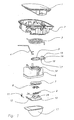
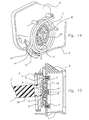
- Figure 1 gives an exploded perspective view of the different parts constituting a sealing system according to the invention.
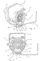
- FIGS 2 and 3 illustrate with perspective views the mechanism of lock controlled by the body door.
- Figures 4 and 5 show the shutter system in its closed state, closed gate, locked bezel and shutter closed.
- Figure 4 gives a perspective view
- Figure 5 a plan view of the system.
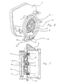
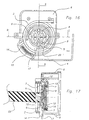
- FIG. 6 is a perspective view
- the Figure 7 is a view. in section along the axis EE appearing on the plan view of the FIG. 9 is another sectional view along the axis AA of FIG. 8, showing the fuel dispensing gun coming against the pallet.
- FIGS. 10 to 13 show the embodiment detail of a telescope, FIG. 10 being a perspective view, Figs. 11 and 12 being plan views of each of the two faces of the telescope and FIG. 13 being a sectional view according to the FF axis of FIG.
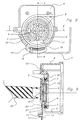
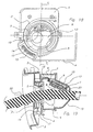
- FIGS. 14 to 17 illustrate the case of a closed system, an open gate, unlocked bezel and shutter closed.
- Figure 14 is a perspective view
- FIG. 15 is a sectional view along the axis DD appearing on the plan view of Figure 16.
- Figure 17 is another sectional view along the axis BB of the Figure 16, showing the fuel dispensing gun providing effort thrust on the pallet along an axis parallel to the axis of the head of the tubing. We can see the crushing of the hairpin spring and the unlocking of the glasses.
- Figures 18 and 19 illustrate the case of an open system, open gate, unlocked bezel and shutter open.
- Fig. 18 is a plan view and the FIG. 19 is a sectional view along the axis CC of FIG. 18. In these figures, can distinguish the shutter in tilted open position, allowing the passage of the dispensing gun.
- FIG. 1 are illustrated, from top to bottom, the different parts component of the shutter system: a door (1) body, a housing of hatch (2), a torsion spring (3), a rod (4), a telescope (5), comprising a tab (17) which carries an orifice (16) and an oblong piece (14) with a slider (15), a body (6) supporting the telescope (5), a compressible seal (7), a pallet (8), a curved pin-shaped compression spring (9), a shutter (10) provided with another torsion spring (11) and a rotational axis (12) and a guide (13) for a dispensing gun.
- the spring (3) acts as a spring restoring rotation of the telescope (5) towards its unlocked position.
- the spring (11) acts as a return spring of the shutter (10) to its position closed.
- FIG. 1 also shows the flattened lugs (23) and (24) located on the around the shutter (10).
- a tank filler neck head can be seen in a closed position, shutter locked, illustrating the gate (1), the hatch (2), the pallet (8), the compression spring in pin (9) terminated by a lug (20) flush with the surface of a notch (19) of the body (6).
- This notch (19) allows the movement of the pin spring (9) beyond the telescope (5).
- FIG. 3 the tubing head in the same situation as in the figure preceding is represented, the hatch housing (2) having been removed in order to show the underlying parts. It distinguishes, in addition to already visible parts in FIG. 2, the body (6) supporting the telescope (5), the guide (13), the tongue (17) of the telescope (5) carrying the orifice (16) in which is inserted the end of the spring (3) for rotating the bezel in position unlocked, here in extended position, bezel (5) locked.
- the tongue (17) also carries an oblong piece (14) with a slide (15), in which a end of the rod (4) is inserted and acts as a slide.
- the rod (4) at its other end inserted into two supports (18) of axes integral with the gate (1).
- Figures 4 and 5 show a closed system, closed gate (no shown), bezel (5) locked and closed shutter.
- the body (6) carrying a notch (19) on the surface of which is flush the pin (20) of the hairpin spring (9) and the paddle (8).
- the tongue (17) of the bezel (5) bears the same elements (14) to (17) and the rod (4) that already described in Figure 3.
- FIG. 9 which is a section along the axis AA of the plan view of the FIG. 8 shows a filling nozzle (22) whose end comes up on the pallet (8).
- the gate is open and the end of the rod (4) (no shown in Figure 6) slid to the left side of the slide (15).
- the bezel (5) remains locked and the shutter (10) locked in position closed because the pin (20) of the pin spring (9) has remained inserted in the notch (21) of the telescope (5).
- the flexible seal (7) is visible on both views in section in Figures 7 and 9.
- Figures 14 to 17 show the situation of the system with the gun distributor (22) pressing on the pallet (8) and compressing the spring into pin (9), the lug (20) terminating the latter being out of the notch (21) of the bezel (5) and entered into the notch (19) facing it on the body (6).
- the spring of torsion (3) has recalled the bezel (5) in the unlocked position by making it turn clockwise, thus unlocking the shutter (10).
Landscapes
- Engineering & Computer Science (AREA)
- Life Sciences & Earth Sciences (AREA)
- Sustainable Development (AREA)
- Sustainable Energy (AREA)
- Chemical & Material Sciences (AREA)
- Combustion & Propulsion (AREA)
- Transportation (AREA)
- Mechanical Engineering (AREA)
- Cooling, Air Intake And Gas Exhaust, And Fuel Tank Arrangements In Propulsion Units (AREA)
- Pipe Accessories (AREA)
- Loading And Unloading Of Fuel Tanks Or Ships (AREA)
- Closures For Containers (AREA)
Priority Applications (1)
| Application Number | Priority Date | Filing Date | Title |
|---|---|---|---|
| EP05101678A EP1538015B1 (fr) | 2001-07-25 | 2002-07-24 | Système d'obturation pour tubulure de remplissage de réservoir à carburant et procédé pour ouvrir cette tubulure |
Applications Claiming Priority (3)
| Application Number | Priority Date | Filing Date | Title |
|---|---|---|---|
| FR0110044 | 2001-07-25 | ||
| FR0110044A FR2827818B1 (fr) | 2001-07-25 | 2001-07-25 | Systeme d'obturation pour tubulure de remplissage de reservoir a carburant et procede pour ouvrir cette tubulure |
| PCT/EP2002/008323 WO2003010022A1 (fr) | 2001-07-25 | 2002-07-24 | Systeme d'obturation pour tubulure de remplissage de reservoir a carburant et procede pour ouvrir cette tubulure |
Related Child Applications (1)
| Application Number | Title | Priority Date | Filing Date |
|---|---|---|---|
| EP05101678A Division EP1538015B1 (fr) | 2001-07-25 | 2002-07-24 | Système d'obturation pour tubulure de remplissage de réservoir à carburant et procédé pour ouvrir cette tubulure |
Publications (2)
| Publication Number | Publication Date |
|---|---|
| EP1414664A1 EP1414664A1 (fr) | 2004-05-06 |
| EP1414664B1 true EP1414664B1 (fr) | 2005-05-18 |
Family
ID=8865971
Family Applications (2)
| Application Number | Title | Priority Date | Filing Date |
|---|---|---|---|
| EP02772105A Expired - Lifetime EP1414664B1 (fr) | 2001-07-25 | 2002-07-24 | Systeme d'obturation pour tubulure de remplissage de reservoir a carburant et procede pour ouvrir cette tubulure |
| EP05101678A Expired - Lifetime EP1538015B1 (fr) | 2001-07-25 | 2002-07-24 | Système d'obturation pour tubulure de remplissage de réservoir à carburant et procédé pour ouvrir cette tubulure |
Family Applications After (1)
| Application Number | Title | Priority Date | Filing Date |
|---|---|---|---|
| EP05101678A Expired - Lifetime EP1538015B1 (fr) | 2001-07-25 | 2002-07-24 | Système d'obturation pour tubulure de remplissage de réservoir à carburant et procédé pour ouvrir cette tubulure |
Country Status (10)
Families Citing this family (45)
| Publication number | Priority date | Publication date | Assignee | Title |
|---|---|---|---|---|
| GB0312184D0 (en) | 2003-05-28 | 2003-07-02 | Feeney Aiden | Delivery flow valve |
| DE10336776B4 (de) | 2003-08-08 | 2010-04-08 | Alfmeier Präzision Aktiengesellschaft Baugruppen und Systemlösungen | Einfüllstutzen für den Kraftstoffbehälter eines Kraftfahrzeuges mit einem automatischen Tankverschluss |
| BRPI0414219A (pt) * | 2003-09-12 | 2006-11-07 | Inergy Automotive Systems Res | sistema para travar um mecanismo de fechamento para um tubo de enchimento de tanque de combustìvel |
| FR2861655B1 (fr) * | 2003-10-31 | 2006-01-06 | Inergy Automotive Systems Res | Dispositif d'obturation d'une tubulure de remplissage d'un reservoir a liquide, reservoir equipe d'un tel dispositif et vehicule automobile comprenant un tel reservoir |
| PT1704234E (pt) | 2003-11-21 | 2012-04-26 | Nycomed Gmbh | Produção do péptido tipo glucagon 2 e de análogos do mesmo |
| DE102004002994B3 (de) * | 2004-01-19 | 2005-09-22 | Itw Automotive Products Gmbh & Co. Kg | Einfüllstutzen für das Einfüllen von Kraftstoff in einen Fahrzeugtank |
| US6880594B1 (en) * | 2004-03-19 | 2005-04-19 | Eaton Corporation | Method and arrangement for sealing a capless fuel tank filler tube |
| JP4490763B2 (ja) * | 2004-08-23 | 2010-06-30 | 本田技研工業株式会社 | 車両用燃料キャップ |
| JP4504772B2 (ja) * | 2004-09-27 | 2010-07-14 | 株式会社ニフコ | 燃料タンクの給油管 |
| FR2879521B1 (fr) * | 2004-12-16 | 2007-03-09 | Inergy Automotive Systems Res | Systeme d'obturation pour tubulure de remplissage de reservoir a carburant |
| FR2879522B1 (fr) * | 2004-12-16 | 2008-05-30 | Inergy Automotive Systems Res | Systeme de verrouillage pour un obturateur integre a une tete de tubulure de remplissage de reservoir a carburant |
| US7165583B1 (en) * | 2005-01-31 | 2007-01-23 | Eaton Corporation | Door latch for capless filler neck |
| FR2881688B1 (fr) * | 2005-02-04 | 2008-09-05 | Inergy Automotive Systems Res | Systeme d'obturation pour tubulure de remplissage de reservoir a carburant |
| ES2314579T3 (es) * | 2005-02-10 | 2009-03-16 | Gerdes Gmbh | Remate de racor cerrable sin tapa para un racor de llenado de un deposito de un vehiculo automovil. |
| US7007726B1 (en) * | 2005-04-18 | 2006-03-07 | Eaton Corporation | Cover closure assembly and method for fuel tank filler |
| FR2886367B1 (fr) * | 2005-05-24 | 2008-12-26 | Inergy Automotive Systems Res | Clapet pour circuit de mise a l'air d'un reservoir a liquide |
| JP4692360B2 (ja) * | 2005-12-02 | 2011-06-01 | 豊田合成株式会社 | タンク用開閉装置 |
| US20070267067A1 (en) * | 2006-05-16 | 2007-11-22 | Water Square Sports Co., Ltd. | Valve for a snorkel |
| FR2901191B1 (fr) * | 2006-05-22 | 2008-12-26 | Inergy Automotive Systems Res | Systeme d'obturation pour tubulure de remplissage de reservoir a carburant |
| DE102006031463A1 (de) * | 2006-07-07 | 2008-01-10 | Itw Automotive Products Gmbh & Co. Kg | Einfüllstutzen für das Einfüllen von Dieselkraftstoff in einen Fahrzeugtank |
| US9234602B2 (en) * | 2006-07-28 | 2016-01-12 | Toyoda Gosei Co., Ltd. | Tank opening-closing device |
| FR2904268B1 (fr) * | 2006-07-31 | 2009-04-24 | Inergy Automotive Systems Res | Systeme de remplissage d'un reservoir |
| JP4838664B2 (ja) * | 2006-08-11 | 2011-12-14 | 株式会社アステア | 給油口の閉鎖装置 |
| GB2443427B (en) * | 2006-11-03 | 2011-03-30 | Fuel Savers Ltd | Valve |
| US20080178962A1 (en) * | 2007-01-22 | 2008-07-31 | Inergy Auto. Systems Research (Societe Anonyme) | Sealing system for fill pipe head and associated pipe |
| AT9945U1 (de) * | 2007-03-27 | 2008-06-15 | Magna Steyr Fuel Systems Gesmb | Einfüllstutzen eines treibstofftanks mit schutz vor fehlbetankung |
| KR100786535B1 (ko) * | 2007-05-07 | 2007-12-17 | 정호순 | 자동차의 필러 튜브 조립체 |
| FR2917340A1 (fr) * | 2007-06-13 | 2008-12-19 | Inergy Automotive Systems Res | Systeme d'obturation pour tete de tubulure de remplissage et tubulure associee. |
| FR2917341A1 (fr) * | 2007-06-14 | 2008-12-19 | Inergy Automotive Systems Res | Systeme d'obturation pour tete de tubulure de remplissage et tubulure associee |
| JP2009001231A (ja) * | 2007-06-25 | 2009-01-08 | Nifco Inc | 給油口用の開閉装置 |
| JP4379518B2 (ja) * | 2007-11-29 | 2009-12-09 | トヨタ自動車株式会社 | 燃料タンクの給油部構造 |
| JP4924445B2 (ja) * | 2008-01-24 | 2012-04-25 | 豊田合成株式会社 | タンク用開閉装置 |
| US20110140412A1 (en) * | 2008-05-08 | 2011-06-16 | Amtrol Licensing Inc. | Support stand for pressure vessel |
| DE102008039311B4 (de) * | 2008-08-22 | 2013-02-21 | Itw Automotive Products Gmbh & Co. Kg | Einfüllstutzen für das Einfüllen von Kraftstoff in einen Fahrzeugtank |
| JP5097221B2 (ja) * | 2010-01-19 | 2012-12-12 | 八千代工業株式会社 | 樹脂製燃料タンクの部品固定構造 |
| EP2679428B1 (en) * | 2011-02-23 | 2017-11-15 | Toyota Jidosha Kabushiki Kaisha | Fuel tank fuel filler structure |
| DE102011117459A1 (de) * | 2011-06-29 | 2013-01-03 | Volkswagen Aktiengesellschaft | Einfüllstutzen für einen Kraftstoffbehälter |
| BR112014020227A8 (pt) * | 2012-02-20 | 2017-07-11 | Honda Motor Co Ltd | Estrutura para seção de abastecimento de tubo abastecedor de combustível |
| CN103335767B (zh) * | 2013-06-13 | 2015-12-16 | 东风亚普汽车部件有限公司 | 汽车燃油箱锁盖扭力测试装置 |
| JP6203106B2 (ja) * | 2014-04-11 | 2017-09-27 | 株式会社ニフコ | 給油口開閉装置 |
| US9873322B2 (en) * | 2015-09-16 | 2018-01-23 | Stant Usa Corp. | Closure assembly for fuel tank filler neck |
| CN105922864A (zh) * | 2016-05-20 | 2016-09-07 | 斯丹德汽车系统(苏州)有限公司 | 一种无盖油箱盖 |
| CN114269588B (zh) * | 2019-05-14 | 2024-07-12 | 伊利诺斯工具制品有限公司 | 铰接式车辆能源门 |
| CN111169278A (zh) * | 2019-09-18 | 2020-05-19 | 宁波海曙广运机电工程有限公司 | 一种便捷油箱盖的自动开闭装置 |
| CN115743790A (zh) * | 2022-12-09 | 2023-03-07 | 楚天科技股份有限公司 | 一种数粒机料门防卡控制方法及数粒机料门 |
Family Cites Families (7)
| Publication number | Priority date | Publication date | Assignee | Title |
|---|---|---|---|---|
| US2145758A (en) * | 1937-02-09 | 1939-01-31 | Roy S Fellows | Tank closure |
| US5145081A (en) * | 1990-10-03 | 1992-09-08 | Trilby, Ltd. | Capless closure for a fuel tank filler pipe |
| DE4305394C1 (de) | 1993-02-22 | 1994-04-07 | Daimler Benz Ag | Verschluß für einen Einfüllstutzen eines Kraftstofftankes |
| FR2710721B1 (fr) * | 1993-09-29 | 1995-11-24 | Journee Paul Sa | Tête de remplissage pour une canalisation de remplissage d'un réservoir de véhicule automobile. |
| DE19520971A1 (de) * | 1995-06-08 | 1996-12-12 | Bayerische Motoren Werke Ag | Tankverschluß, insbesondere an einem Kraftfahrzeug |
| DE19746236A1 (de) * | 1996-11-07 | 1998-05-14 | Volkswagen Ag | Modulkörper zum Abdecken und Verschließen eines Kraftstoffeinfüllstutzens an einem Kraftfahrzeug |
| DE19837783A1 (de) * | 1998-08-20 | 2000-02-24 | Volkswagen Ag | Verschlußanordnung für einen Einfüllstutzen eines Behälters, insbesondere eines Kraftstoffbehälters eines Kraftfahrzeugs |
-
2001
- 2001-07-25 FR FR0110044A patent/FR2827818B1/fr not_active Expired - Fee Related
-
2002
- 2002-07-24 AT AT02772105T patent/ATE295790T1/de not_active IP Right Cessation
- 2002-07-24 WO PCT/EP2002/008323 patent/WO2003010022A1/fr active IP Right Grant
- 2002-07-24 EP EP02772105A patent/EP1414664B1/fr not_active Expired - Lifetime
- 2002-07-24 US US10/484,718 patent/US7063113B2/en not_active Expired - Fee Related
- 2002-07-24 AT AT05101678T patent/ATE526195T1/de not_active IP Right Cessation
- 2002-07-24 DE DE60204226T patent/DE60204226D1/de not_active Expired - Lifetime
- 2002-07-24 KR KR1020047001047A patent/KR100919438B1/ko not_active Expired - Fee Related
- 2002-07-24 BR BR0211412-7A patent/BR0211412A/pt not_active Application Discontinuation
- 2002-07-24 CN CNB028186915A patent/CN100396508C/zh not_active Expired - Fee Related
- 2002-07-24 EP EP05101678A patent/EP1538015B1/fr not_active Expired - Lifetime
- 2002-07-24 JP JP2003515394A patent/JP4141383B2/ja not_active Expired - Fee Related
- 2002-07-24 CN CNA2008100946253A patent/CN101301854A/zh active Pending
Also Published As
| Publication number | Publication date |
|---|---|
| FR2827818A1 (fr) | 2003-01-31 |
| EP1538015A2 (fr) | 2005-06-08 |
| JP2004535329A (ja) | 2004-11-25 |
| EP1538015B1 (fr) | 2011-09-28 |
| CN1558839A (zh) | 2004-12-29 |
| US7063113B2 (en) | 2006-06-20 |
| CN100396508C (zh) | 2008-06-25 |
| US20050257852A1 (en) | 2005-11-24 |
| KR100919438B1 (ko) | 2009-09-29 |
| WO2003010022A1 (fr) | 2003-02-06 |
| KR20040030851A (ko) | 2004-04-09 |
| BR0211412A (pt) | 2004-08-17 |
| ATE526195T1 (de) | 2011-10-15 |
| JP4141383B2 (ja) | 2008-08-27 |
| EP1538015A3 (fr) | 2010-07-14 |
| FR2827818B1 (fr) | 2003-10-24 |
| DE60204226D1 (de) | 2005-06-23 |
| ATE295790T1 (de) | 2005-06-15 |
| CN101301854A (zh) | 2008-11-12 |
| EP1414664A1 (fr) | 2004-05-06 |
Similar Documents
| Publication | Publication Date | Title |
|---|---|---|
| EP1414664B1 (fr) | Systeme d'obturation pour tubulure de remplissage de reservoir a carburant et procede pour ouvrir cette tubulure | |
| EP4003866B1 (fr) | Bouchon à ouverture sécurisée | |
| FR2694920A1 (fr) | Dispositif pour conserver séparés l'un de l'autre au moins deux produits et pour effectuer leur mélange à un instant souhaité. | |
| EP2878872B1 (fr) | Raccord rapide pour la jonction amovible de deux canalisations | |
| FR2743786A1 (fr) | Bouchon pour une ouverture de remplissage d'un reservoir de carburant | |
| FR2861655A1 (fr) | Dispositif d'obturation d'une tubulure de remplissage d'un reservoir a liquide, reservoir equipe d'un tel dispositif et vehicule automobile comprenant un tel reservoir | |
| FR2881688A1 (fr) | Systeme d'obturation pour tubulure de remplissage de reservoir a carburant | |
| FR2904268A1 (fr) | Systeme de remplissage d'un reservoir | |
| EP0581632B1 (fr) | Pipe de remplissage de réservoir de carburant | |
| FR2753138A1 (fr) | Dispositif de remplissage d'un reservoir de carburant de vehicule automobile comportant des moyens de tarage de la pression de gaz | |
| FR2901191A1 (fr) | Systeme d'obturation pour tubulure de remplissage de reservoir a carburant | |
| FR2879521A1 (fr) | Systeme d'obturation pour tubulure de remplissage de reservoir a carburant | |
| EP0773395B1 (fr) | Poignée de commande d'un robinet à verrou inviolable et robinet équipé d'une telle poignée | |
| FR2879135A1 (fr) | Dispositif d'obturation pour tubulure de remplissage de reservoir a carburant | |
| FR2756034A1 (fr) | Poignee a levier a verrou inviolable destinee a equiper un robinet, et robinet equipe d'une telle poignee | |
| EP0885764A1 (fr) | Bouchon de réservoir de carburant pour véhicule. | |
| FR2879522A1 (fr) | Systeme de verrouillage pour un obturateur integre a une tete de tubulure de remplissage de reservoir a carburant | |
| FR2927024A1 (fr) | Systeme de remplissage d'un reservoir | |
| FR2908087A1 (fr) | Systeme de remplissage d'un reservoir | |
| FR2912697A1 (fr) | Systeme d'obturation pour tete de tubulure de remplissage et tubulure associee | |
| FR2934213A1 (fr) | Dispositif anti-siphonage | |
| FR2918610A1 (fr) | Systeme de remplissage d'un reservoir. | |
| FR2908088A1 (fr) | Systeme de remplissage d'un reservoir | |
| FR2883808A1 (fr) | Dispositif antivol et anti-deversement pour reservoir de liquide, notamment reservoir de carburant | |
| EP1027278A1 (fr) | Robinet de distribution de liquide |
Legal Events
| Date | Code | Title | Description |
|---|---|---|---|
| PUAI | Public reference made under article 153(3) epc to a published international application that has entered the european phase |
Free format text: ORIGINAL CODE: 0009012 |
|
| 17P | Request for examination filed |
Effective date: 20040225 |
|
| AK | Designated contracting states |
Kind code of ref document: A1 Designated state(s): AT BE BG CH CY CZ DE DK EE ES FI FR GB GR IE IT LI LU MC NL PT SE SK TR |
|
| AX | Request for extension of the european patent |
Extension state: AL LT LV MK RO SI |
|
| GRAP | Despatch of communication of intention to grant a patent |
Free format text: ORIGINAL CODE: EPIDOSNIGR1 |
|
| GRAS | Grant fee paid |
Free format text: ORIGINAL CODE: EPIDOSNIGR3 |
|
| GRAA | (expected) grant |
Free format text: ORIGINAL CODE: 0009210 |
|
| AK | Designated contracting states |
Kind code of ref document: B1 Designated state(s): AT BE BG CH CY CZ DE DK EE ES FI FR GB GR IE IT LI LU MC NL PT SE SK TR |
|
| PG25 | Lapsed in a contracting state [announced via postgrant information from national office to epo] |
Ref country code: IT Free format text: LAPSE BECAUSE OF FAILURE TO SUBMIT A TRANSLATION OF THE DESCRIPTION OR TO PAY THE FEE WITHIN THE PRESCRIBED TIME-LIMIT;WARNING: LAPSES OF ITALIAN PATENTS WITH EFFECTIVE DATE BEFORE 2007 MAY HAVE OCCURRED AT ANY TIME BEFORE 2007. THE CORRECT EFFECTIVE DATE MAY BE DIFFERENT FROM THE ONE RECORDED. Effective date: 20050518 Ref country code: CZ Free format text: LAPSE BECAUSE OF FAILURE TO SUBMIT A TRANSLATION OF THE DESCRIPTION OR TO PAY THE FEE WITHIN THE PRESCRIBED TIME-LIMIT Effective date: 20050518 Ref country code: NL Free format text: LAPSE BECAUSE OF FAILURE TO SUBMIT A TRANSLATION OF THE DESCRIPTION OR TO PAY THE FEE WITHIN THE PRESCRIBED TIME-LIMIT Effective date: 20050518 Ref country code: GB Free format text: LAPSE BECAUSE OF FAILURE TO SUBMIT A TRANSLATION OF THE DESCRIPTION OR TO PAY THE FEE WITHIN THE PRESCRIBED TIME-LIMIT Effective date: 20050518 Ref country code: AT Free format text: LAPSE BECAUSE OF FAILURE TO SUBMIT A TRANSLATION OF THE DESCRIPTION OR TO PAY THE FEE WITHIN THE PRESCRIBED TIME-LIMIT Effective date: 20050518 Ref country code: IE Free format text: LAPSE BECAUSE OF FAILURE TO SUBMIT A TRANSLATION OF THE DESCRIPTION OR TO PAY THE FEE WITHIN THE PRESCRIBED TIME-LIMIT Effective date: 20050518 Ref country code: TR Free format text: LAPSE BECAUSE OF FAILURE TO SUBMIT A TRANSLATION OF THE DESCRIPTION OR TO PAY THE FEE WITHIN THE PRESCRIBED TIME-LIMIT Effective date: 20050518 Ref country code: SK Free format text: LAPSE BECAUSE OF FAILURE TO SUBMIT A TRANSLATION OF THE DESCRIPTION OR TO PAY THE FEE WITHIN THE PRESCRIBED TIME-LIMIT Effective date: 20050518 Ref country code: FI Free format text: LAPSE BECAUSE OF FAILURE TO SUBMIT A TRANSLATION OF THE DESCRIPTION OR TO PAY THE FEE WITHIN THE PRESCRIBED TIME-LIMIT Effective date: 20050518 Ref country code: EE Free format text: LAPSE BECAUSE OF FAILURE TO SUBMIT A TRANSLATION OF THE DESCRIPTION OR TO PAY THE FEE WITHIN THE PRESCRIBED TIME-LIMIT Effective date: 20050518 |
|
| REG | Reference to a national code |
Ref country code: GB Ref legal event code: FG4D Free format text: NOT ENGLISH |
|
| REG | Reference to a national code |
Ref country code: CH Ref legal event code: EP |
|
| REG | Reference to a national code |
Ref country code: IE Ref legal event code: FG4D Free format text: LANGUAGE OF EP DOCUMENT: FRENCH |
|
| REF | Corresponds to: |
Ref document number: 60204226 Country of ref document: DE Date of ref document: 20050623 Kind code of ref document: P |
|
| PGFP | Annual fee paid to national office [announced via postgrant information from national office to epo] |
Ref country code: DE Payment date: 20050721 Year of fee payment: 4 |
|
| PG25 | Lapsed in a contracting state [announced via postgrant information from national office to epo] |
Ref country code: CY Free format text: LAPSE BECAUSE OF FAILURE TO SUBMIT A TRANSLATION OF THE DESCRIPTION OR TO PAY THE FEE WITHIN THE PRESCRIBED TIME-LIMIT Effective date: 20050724 Ref country code: LU Free format text: LAPSE BECAUSE OF NON-PAYMENT OF DUE FEES Effective date: 20050724 |
|
| PG25 | Lapsed in a contracting state [announced via postgrant information from national office to epo] |
Ref country code: MC Free format text: LAPSE BECAUSE OF NON-PAYMENT OF DUE FEES Effective date: 20050731 Ref country code: BE Free format text: LAPSE BECAUSE OF NON-PAYMENT OF DUE FEES Effective date: 20050731 |
|
| PG25 | Lapsed in a contracting state [announced via postgrant information from national office to epo] |
Ref country code: DK Free format text: LAPSE BECAUSE OF FAILURE TO SUBMIT A TRANSLATION OF THE DESCRIPTION OR TO PAY THE FEE WITHIN THE PRESCRIBED TIME-LIMIT Effective date: 20050818 Ref country code: SE Free format text: LAPSE BECAUSE OF FAILURE TO SUBMIT A TRANSLATION OF THE DESCRIPTION OR TO PAY THE FEE WITHIN THE PRESCRIBED TIME-LIMIT Effective date: 20050818 Ref country code: GR Free format text: LAPSE BECAUSE OF FAILURE TO SUBMIT A TRANSLATION OF THE DESCRIPTION OR TO PAY THE FEE WITHIN THE PRESCRIBED TIME-LIMIT Effective date: 20050818 Ref country code: BG Free format text: LAPSE BECAUSE OF FAILURE TO SUBMIT A TRANSLATION OF THE DESCRIPTION OR TO PAY THE FEE WITHIN THE PRESCRIBED TIME-LIMIT Effective date: 20050818 |
|
| PG25 | Lapsed in a contracting state [announced via postgrant information from national office to epo] |
Ref country code: DE Free format text: LAPSE BECAUSE OF FAILURE TO SUBMIT A TRANSLATION OF THE DESCRIPTION OR TO PAY THE FEE WITHIN THE PRESCRIBED TIME-LIMIT Effective date: 20050819 |
|
| PG25 | Lapsed in a contracting state [announced via postgrant information from national office to epo] |
Ref country code: ES Free format text: LAPSE BECAUSE OF FAILURE TO SUBMIT A TRANSLATION OF THE DESCRIPTION OR TO PAY THE FEE WITHIN THE PRESCRIBED TIME-LIMIT Effective date: 20050829 |
|
| PG25 | Lapsed in a contracting state [announced via postgrant information from national office to epo] |
Ref country code: PT Free format text: LAPSE BECAUSE OF FAILURE TO SUBMIT A TRANSLATION OF THE DESCRIPTION OR TO PAY THE FEE WITHIN THE PRESCRIBED TIME-LIMIT Effective date: 20051024 |
|
| NLV1 | Nl: lapsed or annulled due to failure to fulfill the requirements of art. 29p and 29m of the patents act | ||
| GBV | Gb: ep patent (uk) treated as always having been void in accordance with gb section 77(7)/1977 [no translation filed] |
Effective date: 20050518 |
|
| REG | Reference to a national code |
Ref country code: IE Ref legal event code: FD4D |
|
| PLBE | No opposition filed within time limit |
Free format text: ORIGINAL CODE: 0009261 |
|
| STAA | Information on the status of an ep patent application or granted ep patent |
Free format text: STATUS: NO OPPOSITION FILED WITHIN TIME LIMIT |
|
| 26N | No opposition filed |
Effective date: 20060221 |
|
| PG25 | Lapsed in a contracting state [announced via postgrant information from national office to epo] |
Ref country code: LI Free format text: LAPSE BECAUSE OF NON-PAYMENT OF DUE FEES Effective date: 20060731 Ref country code: CH Free format text: LAPSE BECAUSE OF NON-PAYMENT OF DUE FEES Effective date: 20060731 |
|
| REG | Reference to a national code |
Ref country code: CH Ref legal event code: PL |
|
| BERE | Be: lapsed |
Owner name: INERGY AUTOMOTIVE SYSTEMS RESEARCH (SA) Effective date: 20050731 |
|
| PGFP | Annual fee paid to national office [announced via postgrant information from national office to epo] |
Ref country code: FR Payment date: 20090710 Year of fee payment: 8 |
|
| REG | Reference to a national code |
Ref country code: FR Ref legal event code: ST Effective date: 20110331 |
|
| PG25 | Lapsed in a contracting state [announced via postgrant information from national office to epo] |
Ref country code: FR Free format text: LAPSE BECAUSE OF NON-PAYMENT OF DUE FEES Effective date: 20100802 |