EP1408628A1 - Système de communication mobile TDMA/CDMA - Google Patents
Système de communication mobile TDMA/CDMA Download PDFInfo
- Publication number
- EP1408628A1 EP1408628A1 EP04000783A EP04000783A EP1408628A1 EP 1408628 A1 EP1408628 A1 EP 1408628A1 EP 04000783 A EP04000783 A EP 04000783A EP 04000783 A EP04000783 A EP 04000783A EP 1408628 A1 EP1408628 A1 EP 1408628A1
- Authority
- EP
- European Patent Office
- Prior art keywords
- circuit
- tdma
- signal
- cdma
- mode
- Prior art date
- Legal status (The legal status is an assumption and is not a legal conclusion. Google has not performed a legal analysis and makes no representation as to the accuracy of the status listed.)
- Withdrawn
Links
Images


Classifications
-
- H—ELECTRICITY
- H04—ELECTRIC COMMUNICATION TECHNIQUE
- H04W—WIRELESS COMMUNICATION NETWORKS
- H04W88/00—Devices specially adapted for wireless communication networks, e.g. terminals, base stations or access point devices
- H04W88/08—Access point devices
-
- H—ELECTRICITY
- H04—ELECTRIC COMMUNICATION TECHNIQUE
- H04B—TRANSMISSION
- H04B1/00—Details of transmission systems, not covered by a single one of groups H04B3/00 - H04B13/00; Details of transmission systems not characterised by the medium used for transmission
- H04B1/38—Transceivers, i.e. devices in which transmitter and receiver form a structural unit and in which at least one part is used for functions of transmitting and receiving
- H04B1/40—Circuits
- H04B1/403—Circuits using the same oscillator for generating both the transmitter frequency and the receiver local oscillator frequency
- H04B1/406—Circuits using the same oscillator for generating both the transmitter frequency and the receiver local oscillator frequency with more than one transmission mode, e.g. analog and digital modes
-
- H—ELECTRICITY
- H04—ELECTRIC COMMUNICATION TECHNIQUE
- H04B—TRANSMISSION
- H04B7/00—Radio transmission systems, i.e. using radiation field
- H04B7/24—Radio transmission systems, i.e. using radiation field for communication between two or more posts
- H04B7/26—Radio transmission systems, i.e. using radiation field for communication between two or more posts at least one of which is mobile
- H04B7/2618—Radio transmission systems, i.e. using radiation field for communication between two or more posts at least one of which is mobile using hybrid code-time division multiple access [CDMA-TDMA]
-
- H—ELECTRICITY
- H04—ELECTRIC COMMUNICATION TECHNIQUE
- H04W—WIRELESS COMMUNICATION NETWORKS
- H04W88/00—Devices specially adapted for wireless communication networks, e.g. terminals, base stations or access point devices
- H04W88/02—Terminal devices
- H04W88/06—Terminal devices adapted for operation in multiple networks or having at least two operational modes, e.g. multi-mode terminals
-
- H—ELECTRICITY
- H04—ELECTRIC COMMUNICATION TECHNIQUE
- H04L—TRANSMISSION OF DIGITAL INFORMATION, e.g. TELEGRAPHIC COMMUNICATION
- H04L7/00—Arrangements for synchronising receiver with transmitter
- H04L7/04—Speed or phase control by synchronisation signals
-
- H—ELECTRICITY
- H04—ELECTRIC COMMUNICATION TECHNIQUE
- H04W—WIRELESS COMMUNICATION NETWORKS
- H04W16/00—Network planning, e.g. coverage or traffic planning tools; Network deployment, e.g. resource partitioning or cells structures
- H04W16/24—Cell structures
- H04W16/32—Hierarchical cell structures
Definitions
- This invention relates to a mobile unit communication system for providing communication between a base station and a plurality of mobile units within a service area.
- a first prior art mobile unit communication system for providing communication between one of base stations and a plurality of mobile units within a service area of the base station through the Time Division Multiple Access/Time division Duplex (TDMA/TDD) method is known.
- TDMA/TDD Time Division Multiple Access/Time division Duplex
- a plurality of channels are, i.e., the multiple access is, provided by using a radio wave through time-division. Therefore, a plurality of mobile units in a service area of a base station can communicate with the base station substantially at the same time.
- Time Division Duplex means that the reception of data and transmission of data are switched by time-division, i.e., the reception of the data and the transmission of data are effected alternately.
- a second prior art mobile unit communication system for providing communication between one of base stations and a plurality of mobile units within a service area of the base station through the Code Division Multiple Access/Time division Duplex (CDMA/TDD) method is proposed in "POWER CONTROL IN PACKET SWITCHED TIME DIVISION DUPLEX DIRECT SEQUENCE SPREAD SPECTRUM COMMUNICATIONS", by R.ESMAILZADEH, M. NAKAGAWA, A. KAJIWARA, proc. of VTC '92, PP.989-992, 1992.
- CDMA/TDD Code Division Multiple Access/Time division Duplex
- Time Division Duplex means that the reception of data and transmission of data are switched by time-division, i.e., the reception of the data and the transmission of data are effected alternately.
- the aim of the present invention is to provide an improved mobile unit communication system.
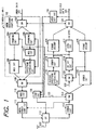
- Fig. 1 is a block diagram of the first embodiment of a mobile unit 12.
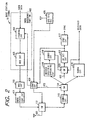
- Fig. 2 is a block diagram of a base station 10 of the TDMA/TDD (Time Division Multiple Access/Time division Duplex) communication method.
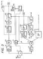
- Fig. 3 is a block diagram of a base station 11 of the CDMA/TDD (Code Division Multiple Access/Time division Duplex) communication method.
- Figs. 4A and 4B are illustrations of the first embodiment of the mobile unit communication system including the base stations 10 and 11 and the mobile units 12.
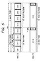
- Fig. 5 is an illustration of of this embodiment of frame formats of TDMA/TDD and CDMA/TDD communication methods.
- a service area 13 of the base station 10 of TDMA/TDD is provided adjacent to a service area 14 of CDMA/TDD as shown in Fig. 4A and service areas 16 and 17 of TDMA/TDD are located within a service area 15 of the base station 11 of CDMA/TDD for example.
- a mobile unit 12 can communicate with the base stations 10 and 11 of TDMA/TDD and CDMA/TDD as shown in Fig. 4B. Therefore, if one mobile unit 12 is located at a point A, it can communicate with the base station 10 of TDMA/TDD and when it moves to a point B, it can communicate with the base station 11 of CDMA/TDD as shown in Fig. 4A. In the case of Fig. 4B, a mobile unit 12 at a point C can communicates with the base stations 10 and 11 of TDMA/TDD and CDMA/TDD.
- frames of transmitted signals of TDMA/TDD and CDMA/TDD have the same frame length as shown in Fig. 5. That is, a commutation signal is transmitted by a base station 10 for a first interval of 2.5 msec and then, for the following 2.5 msec, the communication signal is received.
- One frame of the TDMA/TDD includes four channels, for example, in the time division manner.
- a commutation signal is transmitted by the base station 11 for a first interval of 2.5 msec and then, for the following 2.5 msec, the communication signal is received.
- multi-channels CH1 to N are included in the transmission frame over the interval of 2.5 msec in the code division manner.
- the multi-channels CH1 to N are provided over the interval of 2.5 msec in the code division manner.
- a guard time is provided between two consecutive channel intervals.
- the guard time is provided as guard bits. Therefore, the guard bits can be considered to be included in the frame length.
- a guard time of 0.2 msec is provided between two consecutive frames, that is between the transmission frame and the receiving frame.
- the length of the guard time is determined in accordance with the communication condition, for example, radii of the service areas 14 and 15.
- the base station 10 synchronizes the frame with other adjacent base stations 10 of TDMA/TDD and with adjacent base stations 11 of CDMA/TDD.
- the mobile unit 12 can communicate with both base station 10 and 11 of TDMA/TDD and CDMA/TDD with a simple circuit structure without a frame synchronization with other communication system because the frame length of TDMA/TDD is the same as that of CDMA/TDD and the frame synchronization is effected among the adjacent base stations of TDMA/TDD and CDMA/TDD.
- transmission data 101 is supplied to a framing circuit 104 of a mobile unit 12 in the TDMA mode via a switch 103 and to a framing circuit 106 via the switch 103 in the CDMA mode.
- the framing circuit 104 frames the transmission data 101. That is, the framing circuit 104 supplies the transmission data to the modulation circuit 105 such that the transmission data has a predetermined data length of one channel within a frame and a unique ward for the frame synchronizing and other necessary control data.
- a modulation circuit 105 effects digital-modulation, i.e., the differential coding, PSK modulation, filtering or the like, to an output of the framing circuit 104 and channel controlling.
- the modulation circuit 105 supplies modulated transmission data for one of channel periods 137.
- An output of the modulation circuit 105 is supplied to a modulation circuit 110 via a switch 109 in the TDMA mode.
- the modulation circuit 110 modulates the output of the modulation circuit 105 through frequency- up-converting.
- An output of the modulation circuit 110 is supplied to a transmission power control circuit 111.
- the transmission power control circuit 111 controls a transmission power of the output of the modulation circuit 110 in accordance with a signal receiving level.
- An output of the transmission power control circuit 111 is supplied to an antenna 132 via switch 112 for the transmission frame period.
- the antenna transmits the transmission data 101 to have the transmission frame 133 as shown in Fig. 5 to a base station 10 as a TDMA signal.
- the antenna 132 receives and supplies a TDMA signal from a base station 10 to a demodulation circuit 113.
- the demodulation circuit 113 frequency-down-converts and detects the received TDMA signal to obtain a baseband signal.
- An output of the demodulation circuit 113 is supplied to the transmission power control circuit 111 to control the transmission power to supply the signal receiving level and to a demodulation circuit 115 via a switch 114 in the TDMA mode.
- the demodulation circuit 115 demodulates the output of the demodulation circuit to reproduce the data transmitted from the base station 10.
- An output of the demodulation circuit 115 is supplied to a frame decomposition circuit 125.
- the frame decomposition circuit 126 selectively supplies the received data of a channel used for this mobile unit 12 via the switch 120 in the TDMA/TDD mode.
- the output of the demodulation circuit 115 is supplied to a unique word detection circuit 116 via a switch 123 in the TDMA mode.
- the unique word detection circuit 116 detects the unique word to produce and supplies a frame signal to the framing circuits 104 and 106 and modulation circuit 105, or the like.
- a synchronizing circuit 117 producing synchronizing signal in response to the frame signal from the unique word detection circuit to hold the synchronizing state.
- the synchronizing signal is used for synchronizing operation in respective circuits of this mobile unit 12.
- the mode detection circuit 131 detects the TDMA and CDMA modes from the reproduced received data to produce and supply a TDMA/CDMA mode signal to a control circuit 130.
- the transmission data 101 is supplied to a framing circuit 106 via the switch 103.
- the framing circuit 106 frames the transmission data 101. That is, the framing circuit 106 divides the transmission data to have the predetermined data length of one channel and a unique ward for the frame synchronizing and other necessary control data.
- a modulation circuit 107 effects digital-modulation, i.e., the differential coding, PSK modulation, filtering or the like, to an output of the framing circuit 106.
- An output of the modulation circuit 107 is supplied to a spectrum spreading circuit 108.
- the spectrum spreading circuit 108 effects the spectrum spreading and code division multiple operation.
- the spectrum spreading circuit 108 multiplexes channels CH1 to N within the transmission frame 135 with different codes.
- An output of the spectrum spreading circuit 108 is supplied to a modulation circuit 110 via a switch 109 in the CDMA mode.
- the modulation circuit 110 modulates the output of the spectrum spreading circuit 108 through frequency-up-converting.
- An output of the modulation circuit 110 is supplied to the transmission power control circuit 111.
- the transmission power control circuit 111 controls a transmission power of the output of the modulation circuit 110 in accordance with the signal receiving level.
- the output of the transmission power control circuit 11 is supplied to the antenna 132 via the switch 112 for the transmission frame period.
- the antenna 132 transmits the transmission data 101 to have the transmission frame 133 as shown in Fig. 5 to a base station 11 as a CDMA signal.
- the antenna 132 receives and supplies a CDMA signal from a base station 11 to a demodulation circuit 113.
- the demodulation circuit 113 down-converts and detects the received CDMA signal to obtain a baseband signal.
- the output of the demodulation circuit 113 is supplied to the transmission power control circuit 111 to control the transmission power and to a inverse spectrum spreading circuit 118 via the switch 114.
- the inverse spectrum spreading circuit 118 effects the inverse spectrum spreading operation to reproduce the data transmitted from the base station 12 with a unique code to detects the necessary channel data.
- An output of the inverse spectrum spreading circuit 118 is supplied to a demodulation circuit 119.
- the demodulation circuit 119 effects a digital demodulating, for example, PSK demodulating to the output of the inverse spectrum spreading circuit 118.
- An output of the demodulation circuit 119 is supplied to a frame decomposition circuit 124.
- the frame decomposition circuit 124 reproduces the received data from the output of the demodulation circuit 119. That is, the frame decomposition circuit 124 removes the unique word and other control data from the output of the demodulation circuit 119.
- the received data is outputted via the switch 120 and supplied to a mode detection circuit 131.
- the output of the demodulation circuit 119 is also supplied to the unique word detection circuit 116 via switch 123 in the CDMA mode.
- the unique word detection circuit 116 detects the unique word to produce and supplies a frame signal to the framing circuits 104 and 106 and modulation circuit 105 and the spectrum spreading circuit 108.
- the synchronizing circuit 117 produces the synchronizing signal in response to the frame signal.
- the mode detection circuit 131 detects the TDMA and CDMA modes from the reproduced received data to produce and supply a TDMA/CDMA mode signal to the control circuit 130.
- the control circuit 130 controls the switch 112 in response to the frame signal to effect the TDD operation of transmission of data and the receiving of data alternately.
- the control circuit 130 supplies the received signal by the antenna 132 to the demodulation circuit 113 for the receiving period and determine which mode of TDMA and CDMA is used in the present location of the mobile unit 12 to produce the mode signal. That is, if the received data 121 is present when the switch 114 is connects the demodulation circuit 113 and the demodulation circuit 115, the mobile unit 12 is within a service area of a TDMA base station 10.
- the control circuit 130 changes the mode between the TDMA and CDMA as necessary.
- the control circuit 130 produces receiving/transmitting mode signal supplied to the switch 112 in response to the frame signal from the unique word detection circuit 116.
- the synchronizing circuit 117 produces the synchronizing signal in response to the frame signal.
- the mobile unit 12 at the point A moved from the service area 14 of CDMA/TDD can communicate with the base station 10 without a special frame synchronizing operation because the frames of TDMA/TDD and CDMA/TDD signals are synchronized and have the same frame length.
- the mobile unit 12 at point C can communicate with the base station 10 of TDMA/TDD and the base station 11 of CDMA/TDD. However, either of the base station 10 or 11 is selected normally.
- the frequency band and the amount of data i.e., bits are common between the TDMA/TDD and CDMA/TDD transmission systems, so that the modulation circuit 110, the transmission power control circuit 111, the switch 112, the antenna 132, demodulation circuit 113, are commonly used between the TDMA/TDD and CDMA/TDD.
- the unique word and other control data is commonly defined, so that the unique word detection circuit 116 is used commonly between the TDMA/TDD and CDMA/TDD modes.
- modulation and demodulation operations in the modulation circuit 110 and the demodulation circuit 113 are common, so that a simple structure is provided.
- the switches 103 and 114 are provided for a stable operation. However, these switches 103 and 114 can be omitted.
- the base stations 10 and 11 have the similar circuit structure to the mobile unit 12.
- the base station 10 of TDMA/TDD system transmits data of plurality of channels in TDMA/TDD manner.
- Transmission data of channels CH11 to CH14 is supplied to a framing circuit 404 of the base station 10.
- the framing circuit 104 frames the transmission data. That is, the framing circuit 104 supplies the transmission data to the modulation circuit 405 such that the transmission data has a predetermined data length of a frame and a unique ward for the frame synchronizing and other necessary control data.
- Fig. 6 is an illustration of this embodiment showing data format of one channel of the TDMA/TDD. In the channel CH11, the unique word is present, so that the transmission frame is determined.
- a modulation circuit 405 effects digital-modulation, i.e., the differential coding, PSK modulation, filtering or the like, to an output of the framing circuit 404 and channel controlling to provide channels CH11 to CH14.
- the modulation circuit 405 supplies modulated transmission data of channels CH11 to CH14.
- An output of the modulation circuit 405 is supplied to the modulation circuit 110.
- the modulation circuit 110 modulates the output of the modulation circuit 405 through frequency-up-converting.
- the output of the modulation circuit 110 is supplied to a transmission power control circuit 411 to have a suitable transmission level.
- An output of the transmission power control circuit 411 is supplied to an antenna 432 via switch 112 for the transmission frame period.
- the antenna 432 transmits the transmission data of CH11 to CH14 having the transmission frame 133 as shown in Fig. 5 to mobile units as a TDMA signal.
- the antenna 432 receives and supplies TDMA signals from mobile units 12 within the service area thereof and supplies the TDMA signals to a demodulation circuit 113 through a switch 112 in response to a control circuit 430.
- the demodulation circuit 113 down-converts and detects the received TDMA signals to obtain a baseband signal.
- the output of the demodulation circuit 113 is supplied to the demodulation circuit 115 via the switch 114 controlled by a control signal 422.
- the demodulation circuit 115 demodulates the output of the demodulation circuit 113 to reproduce the data transmitted from the mobile units 12.
- An output of the demodulation circuit 115 is outputted as received data of channels CH11 to CH14.
- a unique word detection circuit 416 detects the unique word in the channel CH11 from adjacent base stations 10 of TDMA/TDD to obtain the frame synchronization via a switch 123 controlled by the control signal 422.
- the base station 10 of TDMA/TDD can receive a CDMA signal from adjacent base stations 11 by the inverse spectrum spreading circuit 118 and the demodulation circuit 119.
- the unique word detection circuit 416 detects the unique word from the CDMA signal to obtain frame synchronization through the inverse spectrum spreading circuit 118 and the demodulation circuit 119, so that the frame synchronization between the base stations 10 and 11 of TDMA and CDMA is provided.
- a GPS signal receiving unit 425 receives a GPS (global positioning system) signal from a GPS satellite (not shown).
- the control circuit 430 obtains the frame synchronization from the TDMA signal, CDMA signal, and GPS signal.
- a synchronizing circuit produces a synchronizing signal in response to the frame signal
- the base station 11 of CDMA has a transmission baseband portion 402 for transmitting only the CDMA signal but both receiving circuits of TDMA and CDMA to obtain the frame synchronization.
- the frame synchronization is effected in both base stations 10 and 11.
- the frame synchronizing is provided by frame synchronization by at least one of base stations 10 and 11.
- the frame synchronization between the base stations 10 and 11 of TDMA and CDMA is provided and the length of frames of TDMA and CDMA is common, so that if the mobile unit 12 at the point A moved from the service area 14 of CDMA/TDD can communicate with the base station 10 without a special frame synchronizing operation.
- Fig. 7 is an illustration of the first embodiment showing a phase relation of frames between the TDMA signal and CDMA signal. As shown in Fig. 7, transmission and receiving frames of the TDMA signal are in phase with those of the CDMA signal, so that the mobile unit 12 having transmitting and receiving circuits of the TDMA and CDMA signals can switch the communication state between the TDMA and CDMA signals without an additional frame synchronizing operation.
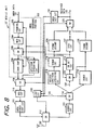
- Fig. 8 is a block diagram of a mobile unit 12' of a second embodiment.
- the unique word for producing the frame signal and other control data are defined commonly between the TDMA and CDMA modes and the same modulation processing is effected to the TDMA and CDMA signals in the transmission baseband portion 202, such as PSK modulation or the like, so that a framing circuit 203 and a modulation circuit 204 are commonly used between the TDMA and CDMA modes.
- transmission data 101 is supplied to a framing circuit 203 of the mobile unit 12' in the TDMA and CDMA modes.
- the framing circuit 104 frames the transmission data 101 on the basis of a frame signal. That is, the framing circuit 203 supplies the transmission data to the modulation circuit 204 such that the transmission data has a predetermined data length of one channel within a frame and a unique ward for the frame synchronizing and other necessary control data.
- a modulation circuit 205 effects digital-modulation, i.e., the differential coding, PSK modulation, filtering or the like, to an output of the framing circuit 203 and channel controlling.
- a switch 205 supplies an output of the modulation circuit 204 to a channel control circuit 206 in the TDMA mode and to the spectrum spreading circuit 108 in the CDMA mode.
- the channel control circuit 205 supplies modulated transmission data for one of channel periods 137.
- An output of the channel control circuit 206 is supplied to the modulation circuit 110 via the switch 109 in the TDMA mode.
- the output of the modulation circuit 204 supplied via the switch 205 is spectrum spreaded by the spectrum spreading circuit 108. That is, the spectrum spreading circuit 108 effects the spectrum spreading and code division multiple operation with a code defining every channels.
- the modulation circuit 110 modulates the output of the modulation circuit 105 through up-converting.
- An output of the modulation circuit 110 is supplied to a transmission power control circuit 111.
- the transmission power control circuit 111 controls a transmission power of the output of the modulation circuit 110 in accordance with a signal receiving level.
- An output of the transmission power control circuit 111 is supplied to an antenna 132 via switch 112 for the transmission frame period.
- the antenna 132 transmits the transmission data 101 to have the transmission frame 133 as shown in Fig. 5 to a base station 10 in the TDMA and CDMA modes.
- the receiving operations of the TDMA and CDMA signals are the same as the first embodiment.
- the unique word for producing the frame signal and other control data are defined commonly between the TDMA and CDMA modes and the same modulation processing is effected to the TDMA and CDMA signals in the transmission baseband portion 202, such as PSK modulation or the like, so that he framing circuit 203 and the modulation circuit 204 are commonly used between the TDMA and CDMA modes.
- a first mobile unit communication system comprising: mobile units; a TDMA (Time Division Multiple Access) base station for transmitting and receiving a TDMA signal having a first frame to/from mobile units within a service area thereof in a TDMA/TDD /Time division Duplex) manner; and a CDMA (Code Division Multiple Access) base station adjacent to the TDMA base station, for transmitting and receiving a CDMA signal having a second frame to/from mobile units in a CDMA/TDD (Code Division Multiple Access/Time division Duplex) manner, at least one of these base stations having a frame synchronizing circuit for detecting a phase between the first and second frames and synchronizing the first and second frames according to the detected phase.
- TDMA Time Division Multiple Access
- Each mobile unit has a first circuit for communicating with the TDMA base station in a TDMA mode; and a second circuit for communicating with the CDMA base station in a CDMA mode.
- First and second frames have the same length and are synchronized to eliminate the necessity of synchronizing operation when the mobile unit moves to the other service area.
- a unique word attached to a framed data is commonly defined between the TDMA and CDMA signals, so that one unique word detection circuit can be used in both TDMA and CDMA modes.
- the TDMA and CDMA signals have the same frequency band, so that one antenna portion can be used in both TDMA and CDMA modes.
- the TDMA and CDMA signals have the same amount of data per channel in a frame, so that modulation and demodulation circuits can be used commonly.
- Such a mobile unit communication system may comprise:
- the second area may be larger than said first area and first area is provided within said second area.
- the first and second base stations may transmit said first and second communication signals to have the same frequency band and said each of mobile units may further comprise an antenna for receiving and transmitting said first and second communication signals and a switch responsive to a mode signal indicative of said first and second modes for supplying said first communication signal between said antenna and said first communication circuit in said first mode and for supplying said second communication signal between said antenna and said second communication circuit in said second mode.
- Each of mobile units may further comprise:
- the first and second communication signals may have first and second frames respectively, said first and second frames having the same amount of data and each of said mobile units further comprising a baseband data processing portion for processing data to be transmitted and for supplying said processed data to said first communication circuit in said first mode and to said second communication circuit in said second mode.
- Each of said mobile units may further comprise a framing circuit for framing data to be transmitted and for supplying said framed data to said first communication circuit in said first mode and to said second communication circuit in said second mode.
- the framing circuit may add a frame synchronizing signal and control data to said data and supply said framed data.
- a digital modulation circuit may be provided for digital-modulating said framed data and supplying said framed data to said first communication in said first mode and said second communication circuit in said second mode.
- a mode detection circuit may be provided for generating a mode signal indicative of said first and second modes in accordance with outputs of said first and second communication circuits.
- a frame detection circuit may be provided for detecting said first frame from said first communication signal from said antenna in said first mode and detecting said second frame from said second communication signal from said antenna in said second mode to produce a frame signal and a control circuit for producing said receiving/transmitting signal in response to said frame signal.
- a mobile unit communication system comprising mobile units; a first base station, having a first service area, for transmitting and receiving first and second CDMA signals to/from mobile units within said first service area respectively, said first CDMA signal having a first frame which includes a plurality of first channels in a time division multiple access and time division duplex manner; and a second base station, having a second service area, for transmitting and receiving first and second TDMA signals to and from mobile units within said second service area respectively, said first TDMA signal having a second frame which includes a plurality of second channels in a code division multiple access and time division duplex manner, said first frame has the same length as said second frame.
- At least one of said first and second base stations further has a frame synchronizing circuit for detecting a phase between said first and second frames and synchronizing said first and second frames with each other in accordance with said detected phase.
- Each of said mobile units (12) has a baseband circuit for framing data to be transmitted on the basis of a frame signal and for digital-modulation of said data framed to produce first and second baseband signals in first and second modes respectively; an up-converting circuit for frequency-up-converting said first baseband signal in said first mode and said second baseband signal in said second mode, a transmission power control circuit for controlling of a power of an output signal from the up-converting portion; an antenna portion for, in a transmission mode, transmitting an output of said transmission control circuit as said second TDMA signal in said first mode and as said second CDMA signal in said second mode and for, in a receiving mode, receiving said first TDMA signal in said first mode and first CDMA signal in said second mode, said transmission and receiving modes being effected in a time division duplex manner; a
- the baseband circuit may have first and second framing circuits for framing said data to be transmitted to have said first and second frame in said first and second modes respectively, a first digital modulation circuit for digital-modulating an output of said first framing circuit, a second digital modulation circuit for digital-modulating an output of said second framing circuit, and a code division multiplexing circuit for code-division-multiplexing to an output of said second digital modulation circuit, and a switch for supplying an output of said first digital modulation circuit as said first baseband signal in said first mode and an output of said code division multiplexing circuit as said second baseband signal in second mode.
- the demodulation circuit may comprise a down-converting circuit for down-converting and detecting said transmitted signal to produce a third baseband signal, a TDMA demodulating circuit for demodulating said third baseband signal, an inverse spectrum spreading circuit for inverse-spectrum spreading said baseband signal, and a switch for outputting an output of said TDMA demodulating circuit in said first mode and an output of said inverse spectrum spreading circuit in said first mode.
- the baseband circuit may have first and second framing circuits for framing said data to be transmitted to have said first and second frame respectively, a first digital modulation circuit for digital-modulating an output of said first framing circuit, a second digital modulation circuit for digital-modulating said second framing circuit, and a code division multiplexing circuit for code-division-multiplexing to an output of said second digital modulation circuit.
- a mobile unit communication system comprises: mobile units; a TDMA base station for transmitting and receiving a TDMA signal having a first frame to/from mobile units within a service area thereof in a TDMA/TDD manner; and a CDMA base station adjacent to the TDMA base station, for transmitting and receiving a CDMA signal having a second frame to/from mobile units in a CDMA/TDD manner, at least one of these base stations having a frame synchronizing circuit for detecting a phase between the first and second frames and synchronizing the first and second frames according to the detected phase.
- Each mobile unit has a first circuit for communicating with the TDMA base station in a TDMA mode; and a second circuit for communicating with the CDMA base station in a CDMA mode.
- First and second frames have the same length and are synchronized to eliminate the necessity of synchronizing operation when the mobile unit moves to the other service area.
- a unique word attached to a framed data is commonly defined between the TDMA and CDMA signals, so that a unique word detection circuit can be used commonly.
- the TDMA and CDMA signals have the same frequency band, so that the antenna portion can be used commonly.
- the TDMA and CDMA signals have the same amount of data per channel in a frame, so that modulation and demodulation circuits can be used commonly.
Landscapes
- Engineering & Computer Science (AREA)
- Computer Networks & Wireless Communication (AREA)
- Signal Processing (AREA)
- Mobile Radio Communication Systems (AREA)
Applications Claiming Priority (3)
| Application Number | Priority Date | Filing Date | Title |
|---|---|---|---|
| JP6009611A JP2992670B2 (ja) | 1994-01-31 | 1994-01-31 | 移動体通信装置 |
| JP961194 | 1994-01-31 | ||
| EP95101226A EP0665659B1 (fr) | 1994-01-31 | 1995-01-30 | Système de communication mobile TDMA/CDMA |
Related Parent Applications (1)
| Application Number | Title | Priority Date | Filing Date |
|---|---|---|---|
| EP95101226A Division EP0665659B1 (fr) | 1994-01-31 | 1995-01-30 | Système de communication mobile TDMA/CDMA |
Publications (1)
| Publication Number | Publication Date |
|---|---|
| EP1408628A1 true EP1408628A1 (fr) | 2004-04-14 |
Family
ID=11725102
Family Applications (3)
| Application Number | Title | Priority Date | Filing Date |
|---|---|---|---|
| EP95101226A Expired - Lifetime EP0665659B1 (fr) | 1994-01-31 | 1995-01-30 | Système de communication mobile TDMA/CDMA |
| EP04000783A Withdrawn EP1408628A1 (fr) | 1994-01-31 | 1995-01-30 | Système de communication mobile TDMA/CDMA |
| EP20040000782 Withdrawn EP1408627A1 (fr) | 1994-01-31 | 1995-01-30 | Système de communication mobile TDMA/CDMA |
Family Applications Before (1)
| Application Number | Title | Priority Date | Filing Date |
|---|---|---|---|
| EP95101226A Expired - Lifetime EP0665659B1 (fr) | 1994-01-31 | 1995-01-30 | Système de communication mobile TDMA/CDMA |
Family Applications After (1)
| Application Number | Title | Priority Date | Filing Date |
|---|---|---|---|
| EP20040000782 Withdrawn EP1408627A1 (fr) | 1994-01-31 | 1995-01-30 | Système de communication mobile TDMA/CDMA |
Country Status (5)
| Country | Link |
|---|---|
| US (1) | US5572516A (fr) |
| EP (3) | EP0665659B1 (fr) |
| JP (1) | JP2992670B2 (fr) |
| CA (1) | CA2141370C (fr) |
| DE (1) | DE69533271T2 (fr) |
Families Citing this family (65)
| Publication number | Priority date | Publication date | Assignee | Title |
|---|---|---|---|---|
| JP3215018B2 (ja) * | 1994-09-09 | 2001-10-02 | 三菱電機株式会社 | 移動通信システム |
| GB2297460B (en) * | 1995-01-28 | 1999-05-26 | Motorola Ltd | Communications system and a method therefor |
| ZA965340B (en) | 1995-06-30 | 1997-01-27 | Interdigital Tech Corp | Code division multiple access (cdma) communication system |
| US6885652B1 (en) | 1995-06-30 | 2005-04-26 | Interdigital Technology Corporation | Code division multiple access (CDMA) communication system |
| US7929498B2 (en) * | 1995-06-30 | 2011-04-19 | Interdigital Technology Corporation | Adaptive forward power control and adaptive reverse power control for spread-spectrum communications |
| US7020111B2 (en) | 1996-06-27 | 2006-03-28 | Interdigital Technology Corporation | System for using rapid acquisition spreading codes for spread-spectrum communications |
| US5680395A (en) * | 1995-08-15 | 1997-10-21 | Qualcomm Incorporated | Method and apparatus for time division duplex pilot signal generation |
| US5732076A (en) * | 1995-10-26 | 1998-03-24 | Omnipoint Corporation | Coexisting communication systems |
| US5689806A (en) * | 1995-12-26 | 1997-11-18 | Motorola, Inc. | Communication receiver for selecting between scanning and locking to a channel and method therefor |
| JP2838994B2 (ja) * | 1995-12-27 | 1998-12-16 | 日本電気株式会社 | データ信号受信装置 |
| US5920822A (en) * | 1996-01-18 | 1999-07-06 | Telefonaktiebolaget Lm Ericsson (Publ) | Formatting of short message service messages in a cellular telephone network |
| GB2309357B (en) | 1996-01-18 | 2000-08-16 | Nokia Mobile Phones Ltd | Communicating between base stations and cellular mobile phones |
| US5793757A (en) * | 1996-02-13 | 1998-08-11 | Telefonaktiebolaget L M Ericsson (Publ) | Telecommunication network having time orthogonal wideband and narrowband sytems |
| US5978679A (en) * | 1996-02-23 | 1999-11-02 | Qualcomm Inc. | Coexisting GSM and CDMA wireless telecommunications networks |
| US5850392A (en) * | 1996-04-10 | 1998-12-15 | Ericsson Inc. | Spread spectrum random access systems and methods for time division multiple access radiotelephone communication systems |
| JP3752724B2 (ja) * | 1996-04-16 | 2006-03-08 | ブラザー工業株式会社 | 無線通信システム |
| US6697415B1 (en) * | 1996-06-03 | 2004-02-24 | Broadcom Corporation | Spread spectrum transceiver module utilizing multiple mode transmission |
| US6101176A (en) * | 1996-07-24 | 2000-08-08 | Nokia Mobile Phones | Method and apparatus for operating an indoor CDMA telecommunications system |
| JP2957483B2 (ja) * | 1996-08-02 | 1999-10-04 | 静岡日本電気株式会社 | 無線選択呼出受信機 |
| GB2320661B (en) * | 1996-12-20 | 2001-10-03 | Dsc Telecom Lp | Processing data transmitted and received over a wireless link connecting a central terminal and a subscriber terminal of a wireless telecommunications system |
| EP0926905B1 (fr) * | 1997-06-16 | 2010-08-11 | Mitsubishi Denki Kabushiki Kaisha | Systeme de communication mobile |
| DE19733860A1 (de) * | 1997-08-05 | 1999-02-11 | Siemens Ag | Einrichtung zur Datenübertragung in Mobilfunknetzen |
| US5912644A (en) * | 1997-08-05 | 1999-06-15 | Wang; James J. M. | Spread spectrum position determination, ranging and communication system |
| JP3897427B2 (ja) | 1997-12-01 | 2007-03-22 | 松下電器産業株式会社 | 基地局装置、移動局装置、移動体通信システム、無線送信方法及び無線受信方法 |
| AU2176499A (en) * | 1998-01-21 | 1999-08-09 | Nokia Mobile Phones Limited | Pulse shaping which compensates for component distortion |
| DE19820736C1 (de) * | 1998-05-08 | 1999-09-30 | Siemens Ag | Verfahren und Basisstationssystem zur Kanalzuteilung in einem Funk-Kommunikationssystem |
| JP3161599B2 (ja) | 1998-07-10 | 2001-04-25 | 日本電気株式会社 | 移動電話システム |
| US7876729B1 (en) | 1998-07-20 | 2011-01-25 | Qualcomm Incorporated | Intersystem base station handover |
| CN1271482A (zh) * | 1998-07-22 | 2000-10-25 | 三菱电机株式会社 | 移动通信系统及移动通信方法 |
| US8050345B1 (en) | 1999-08-09 | 2011-11-01 | Kamilo Feher | QAM and GMSK systems |
| US7548787B2 (en) | 2005-08-03 | 2009-06-16 | Kamilo Feher | Medical diagnostic and communication system |
| JP3646010B2 (ja) * | 1998-09-18 | 2005-05-11 | 株式会社ケンウッド | デジタル衛星放送受信機 |
| US6198730B1 (en) | 1998-10-13 | 2001-03-06 | Motorola, Inc. | Systems and method for use in a dual mode satellite communications system |
| US7596378B1 (en) | 1999-09-30 | 2009-09-29 | Qualcomm Incorporated | Idle mode handling in a hybrid GSM/CDMA network |
| CA2350251A1 (fr) * | 1998-11-02 | 2000-05-11 | Qualcomm Incorporated | Gestion du mode repos dans un reseau hybride gsm/amrc |
| DE19851309C1 (de) * | 1998-11-06 | 2000-07-06 | Siemens Ag | Verfahren zur Datenübertragung in einem Funk-Kommunikationssystem über eine Funkschnittstelle zwischen einer Basisstation und Teilnehmerstation |
| DE19851310A1 (de) * | 1998-11-06 | 2000-05-18 | Siemens Ag | Verfahren zur Datenübertragung in einem Funk-Kommunikationssystem |
| JP3252820B2 (ja) * | 1999-02-24 | 2002-02-04 | 日本電気株式会社 | 復調及び変調回路並びに復調及び変調方法 |
| US9813270B2 (en) | 1999-08-09 | 2017-11-07 | Kamilo Feher | Heart rate sensor and medical diagnostics wireless devices |
| US9373251B2 (en) | 1999-08-09 | 2016-06-21 | Kamilo Feher | Base station devices and automobile wireless communication systems |
| US7260369B2 (en) | 2005-08-03 | 2007-08-21 | Kamilo Feher | Location finder, tracker, communication and remote control system |
| US9307407B1 (en) | 1999-08-09 | 2016-04-05 | Kamilo Feher | DNA and fingerprint authentication of mobile devices |
| KR100602026B1 (ko) * | 1999-11-01 | 2006-07-20 | 유티스타콤코리아 유한회사 | 비동기 시스템에서 동기 시스템으로의 비동기 이동국의핸드오프 처리방법 |
| KR100350481B1 (ko) | 1999-12-30 | 2002-08-28 | 삼성전자 주식회사 | 비동기 이동통신시스템에서 동기 이동통신시스템으로의핸드오프 수행장치 및 방법 |
| IL154151A0 (en) | 2000-07-27 | 2003-07-31 | Interdigital Tech Corp | Adaptive uplink/downlink timeslot assignment in a hybrid wireless time division multiple access/code division multiple access communication system |
| US6591109B2 (en) | 2001-08-17 | 2003-07-08 | Interdigital Technology Corporation | Cross cell user equipment interference reduction in a time division duplex communication system using code division multiple access |
| US7580390B2 (en) * | 2001-11-26 | 2009-08-25 | Qualcomm Incorporated | Reducing handover frequency error |
| KR100485068B1 (ko) * | 2002-07-02 | 2005-04-22 | 엘지전자 주식회사 | 회선데이터 전송속도가 향상된 시디엠에이 단말기 |
| WO2004086780A1 (fr) * | 2003-03-26 | 2004-10-07 | Huawei Technologies Co., Ltd. | Procede de synchronisation initiale de liaisons ascendantes dans un systeme drt |
| KR100560845B1 (ko) | 2003-10-09 | 2006-03-13 | 에스케이 텔레콤주식회사 | Mm-mb 단말기의 모뎀 간 절체 방법 |
| US7226434B2 (en) | 2003-10-31 | 2007-06-05 | Tyco Healthcare Group Lp | Safety shield |
| US7988664B2 (en) | 2004-11-01 | 2011-08-02 | Tyco Healthcare Group Lp | Locking clip with trigger bushing |
| DE10355643B4 (de) * | 2003-11-28 | 2006-04-20 | Infineon Technologies Ag | Mobilstation zum Verarbeiten von Signalen des GSM- und des TD-SCDMA-Funkstandards |
| US7359449B2 (en) | 2004-10-05 | 2008-04-15 | Kamilo Feher | Data communication for wired and wireless communication |
| JP2006186956A (ja) * | 2004-12-03 | 2006-07-13 | Matsushita Electric Ind Co Ltd | マルチモード送信回路、マルチモード送受信回路及びそれを用いた無線通信装置 |
| US7280810B2 (en) | 2005-08-03 | 2007-10-09 | Kamilo Feher | Multimode communication system |
| US10009956B1 (en) | 2017-09-02 | 2018-06-26 | Kamilo Feher | OFDM, 3G and 4G cellular multimode systems and wireless mobile networks |
| JP4986589B2 (ja) * | 2006-11-30 | 2012-07-25 | ユニデン株式会社 | デジタル無線通信システム |
| WO2009042874A1 (fr) | 2007-09-27 | 2009-04-02 | Tyco Healthcare Group Lp | Ensemble cathéter i.v. et dispositif de sécurité pour aiguille |
| EP2075029B1 (fr) | 2007-12-20 | 2010-09-29 | Tyco Healthcare Group LP | Ensemble de blocage de bouchon doté d'un collier à ressort |
| US20100042866A1 (en) * | 2008-08-15 | 2010-02-18 | Mediatek Inc. | Method and Apparatus for Adjusting a System Timer of a Mobile Station |
| JP2011135570A (ja) * | 2009-11-27 | 2011-07-07 | Sanyo Electric Co Ltd | 端末装置 |
| RU2562431C1 (ru) * | 2014-05-13 | 2015-09-10 | Федеральное государственное бюджетное образовательное учреждение высшего профессионального образования "Поволжский государственный университет телекоммуникаций и информатики" (ФГОБУ ВПО ПГУТИ) | Способ параллельной многочастотной передачи цифровой информации по параллельным разнесенным радиоканалам с использованием гибридной модуляции данных |
| CN104883285B (zh) * | 2015-04-27 | 2017-07-11 | 厦门纵行信息科技有限公司 | 一种网络的组网方法以及多模无线通信设备 |
| RU2601136C1 (ru) * | 2015-10-12 | 2016-10-27 | Акционерное общество "Научно-производственное объединение измерительной техники" | Многофункциональное устройство для формирования телеметрических радиосигналов с угловой модуляцией для передачи аналого-цифровой или цифровой информации |
Citations (3)
| Publication number | Priority date | Publication date | Assignee | Title |
|---|---|---|---|---|
| WO1992010891A1 (fr) * | 1990-12-05 | 1992-06-25 | Scs Mobilecom, Inc. | Systeme de telecommunication amdc a spectre etale |
| EP0566257A1 (fr) * | 1992-03-31 | 1993-10-20 | AT&T Corp. | Procédé et dispositif pour diversité d'antenne |
| WO1994001956A2 (fr) * | 1992-06-30 | 1994-01-20 | Motorola Inc. | Reseau de communication a deux modes |
Family Cites Families (1)
| Publication number | Priority date | Publication date | Assignee | Title |
|---|---|---|---|---|
| US5371734A (en) * | 1993-01-29 | 1994-12-06 | Digital Ocean, Inc. | Medium access control protocol for wireless network |
-
1994
- 1994-01-31 JP JP6009611A patent/JP2992670B2/ja not_active Expired - Fee Related
-
1995
- 1995-01-30 EP EP95101226A patent/EP0665659B1/fr not_active Expired - Lifetime
- 1995-01-30 DE DE69533271T patent/DE69533271T2/de not_active Expired - Fee Related
- 1995-01-30 EP EP04000783A patent/EP1408628A1/fr not_active Withdrawn
- 1995-01-30 CA CA002141370A patent/CA2141370C/fr not_active Expired - Fee Related
- 1995-01-30 EP EP20040000782 patent/EP1408627A1/fr not_active Withdrawn
- 1995-01-31 US US08/381,488 patent/US5572516A/en not_active Expired - Lifetime
Patent Citations (3)
| Publication number | Priority date | Publication date | Assignee | Title |
|---|---|---|---|---|
| WO1992010891A1 (fr) * | 1990-12-05 | 1992-06-25 | Scs Mobilecom, Inc. | Systeme de telecommunication amdc a spectre etale |
| EP0566257A1 (fr) * | 1992-03-31 | 1993-10-20 | AT&T Corp. | Procédé et dispositif pour diversité d'antenne |
| WO1994001956A2 (fr) * | 1992-06-30 | 1994-01-20 | Motorola Inc. | Reseau de communication a deux modes |
Also Published As
| Publication number | Publication date |
|---|---|
| CA2141370C (fr) | 2001-01-16 |
| JPH07222227A (ja) | 1995-08-18 |
| DE69533271T2 (de) | 2005-08-18 |
| EP1408627A1 (fr) | 2004-04-14 |
| EP0665659B1 (fr) | 2004-07-21 |
| US5572516A (en) | 1996-11-05 |
| JP2992670B2 (ja) | 1999-12-20 |
| EP0665659A3 (fr) | 1999-09-22 |
| DE69533271D1 (de) | 2004-08-26 |
| EP0665659A2 (fr) | 1995-08-02 |
| CA2141370A1 (fr) | 1995-08-01 |
Similar Documents
| Publication | Publication Date | Title |
|---|---|---|
| US5572516A (en) | Mobile unit communication system | |
| US6480479B1 (en) | CDMA cellular radio transmission system | |
| RU2122290C1 (ru) | Способ (варианты) и базовая станция для выравнивания по времени сигналов для приема в системе радиосвязи с многостанционным доступом и кодовым разделением каналов, абонентский блок | |
| EP2161865B1 (fr) | Station de communication vocale mobile à utiliser dans un système de communication à accès multiple à division de code | |
| US4799252A (en) | Digital radio transmission system | |
| KR100295005B1 (ko) | 코드분할다중화접속방식의무선송수신장치및무선송수신방법 | |
| EP0668669A1 (fr) | Système de communication de données ayant un contrôle de débit d'information ou de débit du codage de source | |
| JP2005506734A (ja) | 移動体通信システムのための低チップレートオプションに適用できる捕捉回路 | |
| JPS6335026A (ja) | デジタル無線伝送系 | |
| US6421330B1 (en) | Apparatus and method for expanding service area of CDMA mobile communication system | |
| US5854784A (en) | Power-saving method for providing synchronization in a communications system | |
| ES2040710T3 (es) | Procedimiento para la transmision de senales digitales en sistemas radiofonia movil. | |
| JPH06224835A (ja) | ディジタル移動無線通信方式 | |
| CA2263775A1 (fr) | Systeme de radiocommunication numerique a constitution simple permettant de varier le mode de capacite de transmission | |
| JP3387413B2 (ja) | 無線送受信方法 | |
| EP0954111A1 (fr) | Système de radiocommunication et méthode pour transmettre des données de contrÔle dans un tel système | |
| JP3190835B2 (ja) | データ通信装置及び方法 | |
| JPH11163779A (ja) | 無線装置 | |
| JPS6322746B2 (fr) | ||
| JPH0927796A (ja) | 符号多重受信装置 | |
| JPH02217027A (ja) | 時分割多元接続用ガードタイム設定方式 | |
| JPH04246923A (ja) | 時分割通信システム | |
| HUP9903668A2 (hu) | Műholdas közvetlen rádiósugárzási rendszer | |
| WO1999027655A2 (fr) | Procede d'etablissement de connexion, et emetteur-recepteur | |
| KR20020030858A (ko) | 비-더블유엘엘(b-wll) 시스템용 무선 정합 장치 및 그방법 |
Legal Events
| Date | Code | Title | Description |
|---|---|---|---|
| PUAI | Public reference made under article 153(3) epc to a published international application that has entered the european phase |
Free format text: ORIGINAL CODE: 0009012 |
|
| AC | Divisional application: reference to earlier application |
Ref document number: 0665659 Country of ref document: EP Kind code of ref document: P |
|
| AK | Designated contracting states |
Kind code of ref document: A1 Designated state(s): DE FR GB |
|
| 17P | Request for examination filed |
Effective date: 20040429 |
|
| RIN1 | Information on inventor provided before grant (corrected) |
Inventor name: KATO, OSAMU Inventor name: MIYA, KAZUYUKI |
|
| AKX | Designation fees paid |
Designated state(s): DE FR GB |
|
| STAA | Information on the status of an ep patent application or granted ep patent |
Free format text: STATUS: THE APPLICATION IS DEEMED TO BE WITHDRAWN |
|
| 18D | Application deemed to be withdrawn |
Effective date: 20051123 |