EP1407835B1 - Vorrichtung zum Reinigen von im wesentlichen quaderförmigen Gegenständen - Google Patents
Vorrichtung zum Reinigen von im wesentlichen quaderförmigen Gegenständen Download PDFInfo
- Publication number
- EP1407835B1 EP1407835B1 EP02022832A EP02022832A EP1407835B1 EP 1407835 B1 EP1407835 B1 EP 1407835B1 EP 02022832 A EP02022832 A EP 02022832A EP 02022832 A EP02022832 A EP 02022832A EP 1407835 B1 EP1407835 B1 EP 1407835B1
- Authority
- EP
- European Patent Office
- Prior art keywords
- articles
- conveyor means
- brushes
- conveyor
- station
- Prior art date
- Legal status (The legal status is an assumption and is not a legal conclusion. Google has not performed a legal analysis and makes no representation as to the accuracy of the status listed.)
- Expired - Lifetime
Links
- 238000004140 cleaning Methods 0.000 title claims description 15
- 239000000428 dust Substances 0.000 claims description 4
- 238000004659 sterilization and disinfection Methods 0.000 claims description 4
- 241000894006 Bacteria Species 0.000 claims description 2
- 238000005507 spraying Methods 0.000 claims description 2
- 239000000645 desinfectant Substances 0.000 claims 1
- 238000010276 construction Methods 0.000 description 1
- 230000007423 decrease Effects 0.000 description 1
- 230000001419 dependent effect Effects 0.000 description 1
- 230000000249 desinfective effect Effects 0.000 description 1
- 238000011161 development Methods 0.000 description 1
- 230000018109 developmental process Effects 0.000 description 1
- 239000006260 foam Substances 0.000 description 1
- -1 for example bristles Substances 0.000 description 1
- 239000000463 material Substances 0.000 description 1
- 230000003287 optical effect Effects 0.000 description 1
- 229920001084 poly(chloroprene) Polymers 0.000 description 1
- 239000000126 substance Substances 0.000 description 1
Images

Classifications
-
- B—PERFORMING OPERATIONS; TRANSPORTING
- B08—CLEANING
- B08B—CLEANING IN GENERAL; PREVENTION OF FOULING IN GENERAL
- B08B1/00—Cleaning by methods involving the use of tools
- B08B1/20—Cleaning of moving articles, e.g. of moving webs or of objects on a conveyor
-
- B—PERFORMING OPERATIONS; TRANSPORTING
- B08—CLEANING
- B08B—CLEANING IN GENERAL; PREVENTION OF FOULING IN GENERAL
- B08B1/00—Cleaning by methods involving the use of tools
- B08B1/30—Cleaning by methods involving the use of tools by movement of cleaning members over a surface
- B08B1/32—Cleaning by methods involving the use of tools by movement of cleaning members over a surface using rotary cleaning members
- B08B1/34—Cleaning by methods involving the use of tools by movement of cleaning members over a surface using rotary cleaning members rotating about an axis parallel to the surface
Definitions
- the present invention relates to a device for cleaning substantially cuboid objects, in particular books, according to the preamble of claim 1.
- DE-A 27 50 822 a device for cleaning books is described and shown, which is passed by means of conveyor belts between two vertical cleaning rollers that clean two narrow sides of the book, while a mounted on a pivoting arm, horizontal brush cleans the book cover. To clean the remaining three surfaces, the book must be turned over by hand and reinserted into the cleaning station.
- the invention has for its object to avoid the disadvantages explained and to provide a device of the type specified, which is simple in construction, works economically and ensures a particularly effective automatic cleaning of all surfaces in one go.
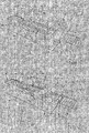
- Figures 1 to 5 show schematic perspective views of an embodiment of the apparatus for cleaning substantially cuboidal objects in different phases of operation.
- 1 denotes the apparatus in its entirety, which serves to clean books 2 here.
- the device 1 has a base 3 carrying a conveyor 4 consisting of belts 5 extending in the horizontal direction.
- the conveyor 4 has a plurality of belts 5 which are endlessly guided around two pulleys 6, one of which is driven, the drive means not being shown any further.
- the upper run of each belt 5 is parallel to the adjacent run and moves in the direction of the arrow F for feeding the books 2, wherein the cylindrical guide rollers 6 have annular grooves for receiving and guiding the circulating belt 5.
- roller conveyor 7 or 8 In the conveying direction F in front of and behind the conveyor 4, a roller conveyor 7 or 8 is mounted, which also extends in the horizontal direction and parallel to the conveying direction F;
- the roller conveyors consist of several driven rollers whose horizontal axes are perpendicular to the conveying direction F.
- two opposing rotating brushes 9 are provided, which are driven by motors, not shown, about their vertical axes.
- two opposing brushes 10 are arranged, which are also rotated about their vertical axes of motors, not shown in rotation.
- two likewise rotating brushes 11 are mounted, namely an upper and an opposite, lower brush, which are rotatable about their horizontal axes, which extend at right angles to the conveying direction F.
- the drive means are also not shown here.
- the brushes 9, 10 and 11 operate in a treatment station for the books 2, which forms the cleaning station.
- a deflector 12 is mounted, which consists of a pin which extends from the base 3 upwards.
- the undercarriage 3 carries two guide elements 13 and 14 which are mounted on both sides of the conveyor 4 and each of which consists of a horizontal bar which is mounted at an angle to the conveying direction F such that it together with the opposite guide element forms a passage zone for the books 2, whose clear width decreases in the conveying direction F.
- a similar guide element 15 is mounted on one side of the roller conveyor 7 in the region of the input zone of the conveyor 4.
- the mentioned brushes 9, 10 and 11 can be made of any suitable material, for example bristles, foam, neoprene or the like.
- each book to be cleaned 2 is placed on the roller conveyor 7, that it comes to rest on the guide member 15 and with its main surface is on the roller conveyor 7, that its longer side is perpendicular to the conveying direction F.
- the roller conveyor 7 pushes the book 2 on the conveyor 4, where it is between the passes through two rotating brush 9, which thereby clean the two opposite surfaces of shorter extension.
- the conveyor 4 then pushes the book 2 against the deflector 12, which holds a corner of the book 2 for a moment ( Figure 2), so that it is pivoted on the conveyor 4 to the deflection pin 12, whereby now its longitudinal extent parallel to the feed direction F is aligned.
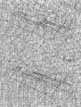
- the thus arranged book 2 then passes between the two guide elements 13 and 14 between the two horizontal brushes 11, which thereby clean the two main surfaces of the book 2 (see Figure 3). Subsequently, the conveyor 4 pushes the book 2 between the two vertical brushes 10, so that the remaining narrow sides are cleaned with the longer extension of the book (see Figure 4).
- the book 2 passes from the conveyor 4 to the roller conveyor 8, where it can be removed from the device 1 ( Figure 5).
- FIG. 2 is indicated schematically that a suction device 24 shown here only as a block can be attached to the device 1 to collect the dust removed from the books 2 and remove it from the housing.
- FIG. 1 shows that a disinfecting device 25, also shown only as a block, can be provided, which serves to remove bacteria or the like which are located on the surfaces of the books 2.
- a disinfection device 25 is known per se and may for example consist of a device for spraying a disinfection substance or of a device for emitting UV rays or of microwaves.
- FIG. 4 implicitly shows, there is the possibility of attaching to the device 1 a conveyor 26 whose entrance area connects, for example, to the exit of the roller conveyor 8 or more generally to the exit of the conveyor 4 and the latter Output in the vicinity of the entrance area of the roller conveyor 7 or more generally of the conveyor 4 is located.
- This conveyor 26 extends with its main part inside or outside of the undercarriage 3 and has the task to return the cleaned books 2 in the vicinity of the input area of the roller conveyor 7.
- FIG. 3 shows that the device 1 may be equipped with sensors 27, preferably optical sensors capable of adjusting the height and / or thickness and / or width of each book 2, or more generally a dimension of each article 2 then automatically adjust one or more of the brushes 9, 10 and / or 11 so that they come to rest on the surfaces of each book or object 2 to be cleaned.
- sensors 27, preferably optical sensors capable of adjusting the height and / or thickness and / or width of each book 2, or more generally a dimension of each article 2 then automatically adjust one or more of the brushes 9, 10 and / or 11 so that they come to rest on the surfaces of each book or object 2 to be cleaned.
Landscapes
- Cleaning In General (AREA)
Description
- Die vorliegende Erfindung betrifft eine Vorrichtung zum Reinigen von im wesentlichen quaderförmigen Gegenständen, insbesondere Büchern, nach dem Oberbegriff des Anspruchs 1.
- In der folgenden Beschreibung wird als Beispiel auf eine Vorrichtung Bezug genommen, die zum Reinigen von nach außen weisenden Flächen von Büchern geeignet ist, ohne daß die Erfindung dadurch ihre Allgemeingültigkeit verliert.
- Bekanntlich werden Bücher, insbesondere dann, wenn sie in Regalfächern von Bibliotheken stehen, mit der Zeit von Staub bedeckt. Der Staub wird dann in regelmäßigen Abständen manuell entfernt, was jedoch nicht immer zu befriedigenden Ergebnissen führt und erheblichen Zeitaufwand bedeutet.
- Aus DE-U 77 39 498 ist ein Buchreinigungsgerat bekannt, der für den Gegenstand des Anspruchs 1 als nächstliegender Stand der Technik angesehen wird, bei dem jedes Buch über Transportrollen durch den Zwischenraum zwischen zwei horizontalen drehbaren Bürsten hindurchgeführt wird, welche die beiden Hauptflächen des Buches reinigen. Eine Reinigungswalze mit vertikaler Drehachse wird so verschoben, daß auch die Schmalseiten des Buches gesäubert werden.
- In DE-A 27 50 822 ist eine Vorrichtung zum Reinigen von Büchern beschrieben und dargestellt, das mittels Förderbändern zwischen zwei vertikalen Reinigungswalzen hindurchgeführt wird, die zwei Schmalseiten des Buches reinigen, während eine an einem Schwenkarm befestigte, horizontale Bürste den Buchdeckel reinigt. Zur Reinigung der übrigen drei Flächen muß das Buch von Hand umgedreht und nochmals in die Reinigungsstation eingeführt werden.
- Der Erfindung liegt die Aufgabe zugrunde, die erläuterten Nachteile zu vermeiden und eine Vorrichtung der angegebenen Bauart zur Verfügung zu stellen, die einfach aufgebaut ist, wirtschaftlich arbeitet und eine besonders wirkungsvolle automatische Reinigung aller Flächen in einem Durchgang gewährleistet.
- Die Lösung dieser Aufgabe ergibt sich aus dem Kennzeichen des Patentanspruchs 1. Vorteilhafte Weiterbildungen sind Gegenstand der abhängigen Ansprüche.
- Die Erfindung ist nachstehend anhand der Zeichnung erläutert, in der ein mögliches Ausführungsbeispiel in nicht einschränkender Weise dargestellt sind. Die Figuren 1 bis 5 zeigen schematische Perspektivenansichten einer Ausführungsform der Vorrichtung zum Reinigen von im wesentlichen quaderförmigen Gegenständen in unterschiedlichen Funktionsphasen.
- In den Figuren 1 bis 5 ist mit 1 die Vorrichtung in ihrer Gesamtheit bezeichnet, die hier zum Reinigen von Büchern 2 dient. Die Vorrichtung 1 hat ein Untergestell 3, das einen Förderer 4 trägt, der aus Riemen 5 besteht, die sich in horizontaler Richtung erstrecken. Der Förderer 4 hat eine Mehrzahl von Riemen 5, die endlos um zwei Umlenkrollen 6 geführt sind, von denen eine angetrieben ist, wobei die Antriebsmittel nicht weiter dargestellt sind. Das obere Trum jedes Riemens 5 ist zum benachbarten Trum parallel angeordnet und bewegt sich in Richtung des Pfeiles F für den Vorschub der Bücher 2, wobei die zylindrischen Umlenkrollen 6 Ringnuten zur Aufnahme und Führung der umlaufenden Riemen 5 aufweisen.
- In Förderrichtung F vor und hinter dem Förderer 4 ist jeweils ein Rollenförderer 7 bzw. 8 angebracht, der sich ebenfalls in horizontaler Richtung und parallel zur Förderrichtung F erstreckt; die Rollenförderer bestehen aus mehreren, angetriebenen Rollen, deren horizontale Achsen rechtwinklig zur Förderrichtung F verlaufen.
- Zu beiden Seiten des Eingangsbereiches des Rollenförderers 7 sind zwei einander gegenüberliegende, rotierende Bürsten 9 vorgesehen, die von nicht dargestellten Motoren um ihre vertikalen Achsen angetrieben werden. In entsprechender Weise sind auch zu beiden Seiten des Ausgangsbereichs des Rollenförderers 8 zwei gegenüberliegende Bürsten 10 angeordnet, die ebenfalls um ihre vertikalen Achsen von nicht gezeigten Motoren in Drehung versetzt werden.
- In einem Zwischenbereich des Förderers 4 sind zwei ebenfalls rotierende Bürsten 11 angebracht, nämlich eine obere und eine gegenüberliegende, untere Bürste, die um ihre horizontalen Achsen drehbar sind, welche rechtwinklig zur Förderrichtung F verlaufen. Die Antriebsmittel sind auch hier nicht weiter dargestellt.
- Die Bürsten 9, 10 und 11 arbeiten in einer Behandlungsstation für die Bücher 2, welche die Reinigungsstation bildet.
- In einem Abschnitt des Förderers 4 zwischen den Bürsten 9 und 11 ist auf einer Seite des Förderers 4 ein Ablenkelement 12 angebracht, das aus einem Stift besteht, der sich von dem Untergestell 3 nach oben erstreckt.
- Zwischen dem Ablenkstift 12 und den Bürsten 10 trägt das Untergestell 3 zwei Führungselemente 13 und 14, die zu beiden Seiten des Förderers 4 angebracht sind und von denen jedes aus einer horizontalen Leiste besteht, die in einem Winkel zur Förderrichtung F so angebracht ist, daß sie zusammen mit dem gegenüberliegenden Führungselement eine Durchtrittszone für die Bücher 2 bildet, deren lichte Weite in Förderrichtung F abnimmt. Ein ähnliches Führungselement 15 ist auf einer Seite des Rollenförderers 7 im Bereich der Eingangszone des Förderers 4 angebracht.
- Die erwähnten Bürsten 9, 10 und 11 können aus jedem geeigneten Material hergestellt werden, beispielsweise aus Borsten, Schaumstoff, Neopren oder dergleichen.
- Im Betrieb wird jedes zu reinigende Buch 2 so auf den Rollenförderer 7 gelegt, daß es zur Anlage an dem Führungselement 15 kommt und mit seiner Hauptfläche so auf dem Rollenförderer 7 liegt, daß seine längere Seite rechtwinklig zur Förderrichtung F verläuft. Wie Figur 1 zeigt, schiebt der Rollenförderer 7 das Buch 2 auf den Förderer 4, wobei es zwischen den beiden rotierenden Bürsten 9 hindurchläuft, die dabei die beiden gegenüberliegenden Flächen kürzerer Erstreckung reinigen. Der Förderer 4 schiebt anschließend das Buch 2 gegen das Ablenkelement 12, das dabei für einen Augenblick eine Ecke des Buches 2 festhält (Figur 2), so daß dieses auf dem Förderer 4 um den Ablenkstift 12 geschwenkt wird, wodurch nun seine Längserstreckung parallel zur Vorschubrichtung F ausgerichtet wird. Das so angeordnete Buch 2 gelangt dann zwischen den beiden Führungselementen 13 und 14 zwischen die beiden horizontalen Bürsten 11, die dabei die beiden Hauptflächen des Buches 2 reinigen (vgl. Figur 3). Im Anschluß daran schiebt der Förderer 4 das Buch 2 zwischen die beiden vertikalen Bürsten 10, so daß die restlichen Schmalseiten mit der längeren Erstreckung des Buches gereinigt werden (vgl. Figur 4).
- Am Ende dieser Reinigungsphasen gelangt das Buch 2 von dem Förderer 4 auf den Rollenförderer 8, wo es von der Vorrichtung 1 abgenommen werden kann (Figur 5).
- Es ist darauf hinzuweisen, daß anstelle der rotierenden Bürsten 9, 10 und 11 Bürsten verwendet werden können, die auf geradlinigen oder gekrümmten Bahnen verschoben werden können.
- In Figur 2 ist schematisch angedeutet, daß eine hier nur als Block dargestellte Saugvorrichtung 24 an der Vorrichtung 1 angebracht werden kann, um den von den Büchern 2 entfernten Staub zu sammeln und aus dem Gehäuse abzuführen.
- In Figur 1 ist dargestellt, daß eine ebenfalls nur als Block gezeigte Desinfektionseinrichtung 25 vorgesehen werden kann, die dazu dient, Bakterien oder dergleichen, die sich auf den Flächen der Bücher 2 befinden, zu entfernen. Eine solche Desinfektionseinrichtung 25 ist an sich bekannt und kann beispielsweise aus einer Vorrichtung zum Versprühen einer Desinfektionssubstanz oder aus einer Vorrichtung zur Abgabe von UV-Strahlen oder von Mikrowellen bestehen.
- Schließlich besteht, wie Figur 4 andeutungsweise zeigt, die Möglichkeit, an der Vorrichtung 1 einen Förderer 26 anzubringen, dessen Eingangsbereich beispielsweise an den Ausgang des Rollenförderers 8 oder ganz allgemein an den Ausgang des Förderers 4 anschließt und dessen Ausgang in der Nähe des Eingangsbereiches des Rollenförderers 7 oder ganz allgemein des Förderers 4 liegt. Dieser Förderer 26 erstreckt sich mit seinem Hauptteil innerhalb oder auch außerhalb des Untergestells 3 und hat die Aufgabe, die gereinigten Bücher 2 in die Nähe des Eingangsbereiches des Rollenförderers 7 zurückzuführen.
- In Figur 3 ist schließlich dargestellt, daß die Vorrichtung 1 mit Sensoren 27 ausgerüstet sein kann, vorzugsweise optischen Sensoren, die in der Lage sind, die Höhe und/oder Stärke und/oder Breite jedes Buches 2 oder ganz allgemein eine Abmessung jedes Gegenstandes 2 zu erkennen, um dann automatisch eine oder mehrere der Bürsten 9, 10 und/oder 11 zu verstellen, damit diese zur Anlage an den zu reinigenden Flächen jedes Buches oder Gegenstandes 2 gelangen.
Claims (9)
- Vorrichtung zum Reinigen von quaderförmigen Gegenständen, insbesondere Büchern, umfassend ein Untergestell (3) mit Fördermitteln (7, 4, 8) für den Transport der Gegenstände (2) durch eine Reinigungsstation, in der wenigstens ein Bürstenpaar (11) mit um horizontale Achsen drehbaren Bürsten (11) angeordnet ist, welche zu beiden Seiten einer durch die Fördermittel (7, 4, 8) vorgegebenen, geradlinigen Vorschubbahn angeordnet sind, dadurch gekennzeichnet, daß die Reinigungsstation drei Bürstenpaare (9, 10, 11) aufweist, wobei die Bürsten (9, 10) der zwei weiteren Bürstenpaare um vertikale Achsen drehbar sind und die Bürsten (9, 10) jedes Paares zu beiden Seiten der durch die Fördermittel (4) vorgegebenen, geradlinigen Vorschubbahn angeordnet sind.
- Vorrichtung nach Anspruch 1, wobei die Fördermittel (4) in der Reinigungsstation aus einem Riemenförderer mit einer Mehrzahl von Riemen (5) bestehen, die in horizontaler Richtung um zwei Umlenkrollen (6) laufen, von denen wenigstens eine angetrieben ist.
- Vorrichtung nach Anspruch 1 oder 2, mit Ablenkmittel in Form eines Stiftes (12), der sich von dem Untergestell (3) nach oben erstreckt, entlang der Vorschubbahn der Gegenstände (2) auf einer Seite der Fördermittel (4) angebracht ist und dazu dient, die Ausrichtung der Gegenstände (2) zu verändern.
- Vorrichtung nach einem der vorhergehenden Ansprüche, mit Führungselemente (13, 14) für die Gegenstände (2), die als horizontale Leisten ausgebildet und zu beiden Seiten der Fördermittel (4) in einem Winkel zur Förderrichtung (F) angebracht sind.
- Vorrichtung nach einem der vorhergehenden Ansprüche, mit eine Saugvorrichtung (24) zum Abführen des von den Gegenständen (2) entfernten Staubes aus der Vorrichtung (1).
- Vorrichtung nach einem der vorhergehenden Ansprüche, mit eine Desinfektionseinrichtung (25) zum Entfernen von auf den Oberflächen der Gegenstände (2) befindlichen Bakterien.
- Vorrichtung nach Anspruch 6, wobei die Desinfektionseinrichtung (25) Sprühorgane zum Ausbringen einer Desinfektionssubstanz aufweist.
- Vorrichtung nach einem der vorhergehenden Ansprüche, mit weitere Fördermittel (26), die eine Eingangsstation im Anschluß an die Ausgangsstation der Fördermittel (4) und eine Ausgangsstation in der Nähe der Eingangsstation der Fördermittel (4) haben.
- Vorrichtung nach einem der vorhergehenden Ansprüche, mit Sensoren (27) zum Erkennen wenigstens einer Abmessung der Gegenstände (2) und zum Verstellen wenigstens einer der Bürsten (9, 10, 11) derart, daß diese in Berührung mit jedem der Gegenstände (2) gelangt.
Priority Applications (4)
| Application Number | Priority Date | Filing Date | Title |
|---|---|---|---|
| ES02022832T ES2280470T3 (es) | 2002-10-12 | 2002-10-12 | Dispositivo para limpiar articulos esencialmente paralelepipedicos. |
| DE50209296T DE50209296D1 (de) | 2002-10-12 | 2002-10-12 | Vorrichtung zum Reinigen von im wesentlichen quaderförmigen Gegenständen |
| SI200230514T SI1407835T1 (sl) | 2002-10-12 | 2002-10-12 | Naprava za čiščenje v bistvu kvadrastih predmetov |
| EP02022832A EP1407835B1 (de) | 2002-10-12 | 2002-10-12 | Vorrichtung zum Reinigen von im wesentlichen quaderförmigen Gegenständen |
Applications Claiming Priority (1)
| Application Number | Priority Date | Filing Date | Title |
|---|---|---|---|
| EP02022832A EP1407835B1 (de) | 2002-10-12 | 2002-10-12 | Vorrichtung zum Reinigen von im wesentlichen quaderförmigen Gegenständen |
Publications (2)
| Publication Number | Publication Date |
|---|---|
| EP1407835A1 EP1407835A1 (de) | 2004-04-14 |
| EP1407835B1 true EP1407835B1 (de) | 2007-01-17 |
Family
ID=32010970
Family Applications (1)
| Application Number | Title | Priority Date | Filing Date |
|---|---|---|---|
| EP02022832A Expired - Lifetime EP1407835B1 (de) | 2002-10-12 | 2002-10-12 | Vorrichtung zum Reinigen von im wesentlichen quaderförmigen Gegenständen |
Country Status (4)
| Country | Link |
|---|---|
| EP (1) | EP1407835B1 (de) |
| DE (1) | DE50209296D1 (de) |
| ES (1) | ES2280470T3 (de) |
| SI (1) | SI1407835T1 (de) |
Cited By (1)
| Publication number | Priority date | Publication date | Assignee | Title |
|---|---|---|---|---|
| WO2011021136A1 (en) | 2009-08-21 | 2011-02-24 | Oracle S.R.L. | Dusting equipment |
Families Citing this family (5)
| Publication number | Priority date | Publication date | Assignee | Title |
|---|---|---|---|---|
| EP1736251A1 (de) * | 2005-06-22 | 2006-12-27 | TiGiEmme s.r.l. | Vorrichtung zum Reinigen von im wesentlichen quaderförmigen Gegenständen, insbesondere Büchern |
| CN103464398A (zh) * | 2013-09-04 | 2013-12-25 | 长兴大宇科机电有限公司 | 铅酸电池中密极板刷极板侧边框机构 |
| CN104624534A (zh) * | 2013-09-04 | 2015-05-20 | 长兴大宇科机电有限公司 | 改进型铅酸电池中密极板分刷一体机 |
| CN106552781A (zh) * | 2016-12-08 | 2017-04-05 | 天津市百利纽泰克电气科技有限公司 | 互感器表面清洁用的自动清洁设备 |
| WO2018109653A2 (en) * | 2016-12-13 | 2018-06-21 | Shingne Sadanand | Frame cleaning machine |
Family Cites Families (3)
| Publication number | Priority date | Publication date | Assignee | Title |
|---|---|---|---|---|
| US1387884A (en) * | 1920-05-27 | 1921-08-16 | Jay E Cross | Apparatus for cleaning book-covers and the like |
| DE2750822A1 (de) * | 1977-11-14 | 1979-05-17 | Geb Querkowsky Regine Nitschke | Vorrichtung zum reinigen von buechern |
| DE7739498U1 (de) * | 1977-12-24 | 1979-10-04 | Milke, Siegfried, 7550 Rastatt | Buchreinigungsgeraet |
-
2002
- 2002-10-12 EP EP02022832A patent/EP1407835B1/de not_active Expired - Lifetime
- 2002-10-12 ES ES02022832T patent/ES2280470T3/es not_active Expired - Lifetime
- 2002-10-12 SI SI200230514T patent/SI1407835T1/sl unknown
- 2002-10-12 DE DE50209296T patent/DE50209296D1/de not_active Expired - Fee Related
Cited By (1)
| Publication number | Priority date | Publication date | Assignee | Title |
|---|---|---|---|---|
| WO2011021136A1 (en) | 2009-08-21 | 2011-02-24 | Oracle S.R.L. | Dusting equipment |
Also Published As
| Publication number | Publication date |
|---|---|
| SI1407835T1 (sl) | 2007-08-31 |
| ES2280470T3 (es) | 2007-09-16 |
| EP1407835A1 (de) | 2004-04-14 |
| DE50209296D1 (de) | 2007-03-08 |
Similar Documents
| Publication | Publication Date | Title |
|---|---|---|
| DE69101856T2 (de) | Gerät zum Sortieren oder anders Behandeln von Gegenständen. | |
| DE2760290C2 (de) | ||
| DE29518639U1 (de) | Vorrichtung zum Transportieren von Behältern vorbei an einer Einrichtung zum Inspizieren des Bodens der Behälter | |
| DE9310623U1 (de) | Inspektionsmaschine für Flaschen o.dgl. | |
| AT402195B (de) | Vorrichtung zum fördern von glastafeln | |
| EP0566831A1 (de) | Vorrichtung zum mechanischen Reinigen von Oberflächen | |
| DE3872155T2 (de) | Reinigungsvorrichtung mit endlosem, rotierendem band, insbesondere zum reinigen eines foerderbandes oder von gegenstaende tragenden flaechen. | |
| EP1407835B1 (de) | Vorrichtung zum Reinigen von im wesentlichen quaderförmigen Gegenständen | |
| EP0606591A1 (de) | Vorrichtung zur Reinigung von Lamellen | |
| CH658847A5 (de) | Bandfoerdereinrichtung. | |
| AT404326B (de) | Vorrichtung zum reinigen von profilen | |
| AT514262B1 (de) | Bearbeitungsanlage und Schleifeinheit | |
| EP1700643A2 (de) | Behälteraufgabe | |
| DE3333175C1 (de) | Vorrichtung zum Reinigen von Glasplatten | |
| DE3506556A1 (de) | Verfahren und vorrichtung zum reinigen von flaechigen kleinteilen, insbesondere muenzen | |
| DE69407511T2 (de) | Teile-Förderer | |
| DE2531507C2 (de) | Vorrichtung zum Sortieren und Klassieren lebender Fische | |
| EP3166089A1 (de) | Rücknahmevorrichtung für leergut | |
| DE3331217C2 (de) | ||
| DE19624552C2 (de) | Inspektionsmaschine für Flaschen oder dergleichen | |
| DE60001010T2 (de) | Druckplattenwaschvorrichtung | |
| DE2030118C3 (de) | Maschine zum Schleifen und Polieren der gekrümmten Oberfläche eines hohlen Glasgegenstandes, insbesondere des Bildschirmes einer Fernsehröhre | |
| DE3037396C2 (de) | Vorrichtung zum Reinigen von Werkstücken | |
| EP3744225B1 (de) | Vorrichtung zum bearbeiten von flächen | |
| DE2542463A1 (de) | Vorrichtung zum kantenbeizen und/oder -lackieren plattenfoermiger werkstuecke |
Legal Events
| Date | Code | Title | Description |
|---|---|---|---|
| PUAI | Public reference made under article 153(3) epc to a published international application that has entered the european phase |
Free format text: ORIGINAL CODE: 0009012 |
|
| AK | Designated contracting states |
Kind code of ref document: A1 Designated state(s): AT BE BG CH CY CZ DE DK EE ES FI FR GB GR IE IT LI LU MC NL PT SE SK TR |
|
| AX | Request for extension of the european patent |
Extension state: AL LT LV MK RO SI |
|
| 17P | Request for examination filed |
Effective date: 20040925 |
|
| AKX | Designation fees paid |
Designated state(s): AT BE BG CH CY CZ DE DK EE ES FI FR GB GR IE IT LI LU MC NL PT SE SK TR |
|
| AXX | Extension fees paid |
Extension state: RO Payment date: 20041009 Extension state: SI Payment date: 20041009 |
|
| 17Q | First examination report despatched |
Effective date: 20050705 |
|
| GRAP | Despatch of communication of intention to grant a patent |
Free format text: ORIGINAL CODE: EPIDOSNIGR1 |
|
| GRAS | Grant fee paid |
Free format text: ORIGINAL CODE: EPIDOSNIGR3 |
|
| GRAA | (expected) grant |
Free format text: ORIGINAL CODE: 0009210 |
|
| AK | Designated contracting states |
Kind code of ref document: B1 Designated state(s): AT BE BG CH CY CZ DE DK EE ES FI FR GB GR IE IT LI LU MC NL PT SE SK TR |
|
| AX | Request for extension of the european patent |
Extension state: RO SI |
|
| PG25 | Lapsed in a contracting state [announced via postgrant information from national office to epo] |
Ref country code: IE Free format text: LAPSE BECAUSE OF FAILURE TO SUBMIT A TRANSLATION OF THE DESCRIPTION OR TO PAY THE FEE WITHIN THE PRESCRIBED TIME-LIMIT Effective date: 20070117 Ref country code: DK Free format text: LAPSE BECAUSE OF FAILURE TO SUBMIT A TRANSLATION OF THE DESCRIPTION OR TO PAY THE FEE WITHIN THE PRESCRIBED TIME-LIMIT Effective date: 20070117 Ref country code: FI Free format text: LAPSE BECAUSE OF FAILURE TO SUBMIT A TRANSLATION OF THE DESCRIPTION OR TO PAY THE FEE WITHIN THE PRESCRIBED TIME-LIMIT Effective date: 20070117 |
|
| REG | Reference to a national code |
Ref country code: GB Ref legal event code: FG4D Free format text: NOT ENGLISH |
|
| REG | Reference to a national code |
Ref country code: CH Ref legal event code: EP |
|
| REG | Reference to a national code |
Ref country code: IE Ref legal event code: FG4D Free format text: LANGUAGE OF EP DOCUMENT: GERMAN |
|
| REF | Corresponds to: |
Ref document number: 50209296 Country of ref document: DE Date of ref document: 20070308 Kind code of ref document: P |
|
| PG25 | Lapsed in a contracting state [announced via postgrant information from national office to epo] |
Ref country code: SE Free format text: LAPSE BECAUSE OF FAILURE TO SUBMIT A TRANSLATION OF THE DESCRIPTION OR TO PAY THE FEE WITHIN THE PRESCRIBED TIME-LIMIT Effective date: 20070417 |
|
| PG25 | Lapsed in a contracting state [announced via postgrant information from national office to epo] |
Ref country code: BG Free format text: LAPSE BECAUSE OF THE APPLICANT RENOUNCES Effective date: 20070418 |
|
| GBT | Gb: translation of ep patent filed (gb section 77(6)(a)/1977) |
Effective date: 20070425 |
|
| ET | Fr: translation filed | ||
| PG25 | Lapsed in a contracting state [announced via postgrant information from national office to epo] |
Ref country code: PT Free format text: LAPSE BECAUSE OF FAILURE TO SUBMIT A TRANSLATION OF THE DESCRIPTION OR TO PAY THE FEE WITHIN THE PRESCRIBED TIME-LIMIT Effective date: 20070618 |
|
| REG | Reference to a national code |
Ref country code: CH Ref legal event code: NV Representative=s name: AMMANN PATENTANWAELTE AG BERN |
|
| REG | Reference to a national code |
Ref country code: IE Ref legal event code: FD4D |
|
| REG | Reference to a national code |
Ref country code: ES Ref legal event code: FG2A Ref document number: 2280470 Country of ref document: ES Kind code of ref document: T3 |
|
| PLBE | No opposition filed within time limit |
Free format text: ORIGINAL CODE: 0009261 |
|
| STAA | Information on the status of an ep patent application or granted ep patent |
Free format text: STATUS: NO OPPOSITION FILED WITHIN TIME LIMIT |
|
| PG25 | Lapsed in a contracting state [announced via postgrant information from national office to epo] |
Ref country code: SK Free format text: LAPSE BECAUSE OF FAILURE TO SUBMIT A TRANSLATION OF THE DESCRIPTION OR TO PAY THE FEE WITHIN THE PRESCRIBED TIME-LIMIT Effective date: 20070117 |
|
| RAP2 | Party data changed (patent owner data changed or rights of a patent transferred) |
Owner name: ORACLE S.R.L. |
|
| 26N | No opposition filed |
Effective date: 20071018 |
|
| PG25 | Lapsed in a contracting state [announced via postgrant information from national office to epo] |
Ref country code: CZ Free format text: LAPSE BECAUSE OF FAILURE TO SUBMIT A TRANSLATION OF THE DESCRIPTION OR TO PAY THE FEE WITHIN THE PRESCRIBED TIME-LIMIT Effective date: 20070117 |
|
| NLT2 | Nl: modifications (of names), taken from the european patent patent bulletin |
Owner name: ORACLE S.R.L. Effective date: 20071219 |
|
| REG | Reference to a national code |
Ref country code: CH Ref legal event code: PUE Owner name: ORACLE S.R.L. Free format text: TIGIEMME S.R.L.#VIALE MAZZINI, 8#41058 VIGNOLA (MODENA) (IT) -TRANSFER TO- ORACLE S.R.L.#VIALE EUROPA 9#36053 GAMBELLARA (IT) |
|
| PG25 | Lapsed in a contracting state [announced via postgrant information from national office to epo] |
Ref country code: GR Free format text: LAPSE BECAUSE OF FAILURE TO SUBMIT A TRANSLATION OF THE DESCRIPTION OR TO PAY THE FEE WITHIN THE PRESCRIBED TIME-LIMIT Effective date: 20070418 |
|
| PG25 | Lapsed in a contracting state [announced via postgrant information from national office to epo] |
Ref country code: MC Free format text: LAPSE BECAUSE OF NON-PAYMENT OF DUE FEES Effective date: 20071031 |
|
| NLS | Nl: assignments of ep-patents |
Owner name: ORACLE S.R.L. Effective date: 20080331 |
|
| PGFP | Annual fee paid to national office [announced via postgrant information from national office to epo] |
Ref country code: NL Payment date: 20080930 Year of fee payment: 7 |
|
| REG | Reference to a national code |
Ref country code: SI Ref legal event code: SP73 Owner name: ORACLE S.R.L.; IT Effective date: 20080923 |
|
| PG25 | Lapsed in a contracting state [announced via postgrant information from national office to epo] |
Ref country code: EE Free format text: LAPSE BECAUSE OF FAILURE TO SUBMIT A TRANSLATION OF THE DESCRIPTION OR TO PAY THE FEE WITHIN THE PRESCRIBED TIME-LIMIT Effective date: 20070117 |
|
| PGFP | Annual fee paid to national office [announced via postgrant information from national office to epo] |
Ref country code: CH Payment date: 20081031 Year of fee payment: 7 |
|
| PGFP | Annual fee paid to national office [announced via postgrant information from national office to epo] |
Ref country code: AT Payment date: 20081014 Year of fee payment: 7 Ref country code: ES Payment date: 20081020 Year of fee payment: 7 |
|
| PGFP | Annual fee paid to national office [announced via postgrant information from national office to epo] |
Ref country code: IT Payment date: 20081022 Year of fee payment: 7 Ref country code: BE Payment date: 20081013 Year of fee payment: 7 |
|
| PGFP | Annual fee paid to national office [announced via postgrant information from national office to epo] |
Ref country code: FR Payment date: 20081017 Year of fee payment: 7 |
|
| PGFP | Annual fee paid to national office [announced via postgrant information from national office to epo] |
Ref country code: DE Payment date: 20081224 Year of fee payment: 7 |
|
| PGFP | Annual fee paid to national office [announced via postgrant information from national office to epo] |
Ref country code: GB Payment date: 20081008 Year of fee payment: 7 |
|
| PG25 | Lapsed in a contracting state [announced via postgrant information from national office to epo] |
Ref country code: CY Free format text: LAPSE BECAUSE OF FAILURE TO SUBMIT A TRANSLATION OF THE DESCRIPTION OR TO PAY THE FEE WITHIN THE PRESCRIBED TIME-LIMIT Effective date: 20070117 |
|
| PG25 | Lapsed in a contracting state [announced via postgrant information from national office to epo] |
Ref country code: LU Free format text: LAPSE BECAUSE OF NON-PAYMENT OF DUE FEES Effective date: 20071012 |
|
| PG25 | Lapsed in a contracting state [announced via postgrant information from national office to epo] |
Ref country code: TR Free format text: LAPSE BECAUSE OF FAILURE TO SUBMIT A TRANSLATION OF THE DESCRIPTION OR TO PAY THE FEE WITHIN THE PRESCRIBED TIME-LIMIT Effective date: 20070117 |
|
| BERE | Be: lapsed |
Owner name: *ORACLE S.R.L. Effective date: 20091031 |
|
| REG | Reference to a national code |
Ref country code: NL Ref legal event code: V1 Effective date: 20100501 |
|
| REG | Reference to a national code |
Ref country code: CH Ref legal event code: PL |
|
| REG | Reference to a national code |
Ref country code: FR Ref legal event code: ST Effective date: 20100630 |
|
| PG25 | Lapsed in a contracting state [announced via postgrant information from national office to epo] |
Ref country code: DE Free format text: LAPSE BECAUSE OF NON-PAYMENT OF DUE FEES Effective date: 20100501 Ref country code: NL Free format text: LAPSE BECAUSE OF NON-PAYMENT OF DUE FEES Effective date: 20100501 Ref country code: FR Free format text: LAPSE BECAUSE OF NON-PAYMENT OF DUE FEES Effective date: 20091102 |
|
| PG25 | Lapsed in a contracting state [announced via postgrant information from national office to epo] |
Ref country code: AT Free format text: LAPSE BECAUSE OF NON-PAYMENT OF DUE FEES Effective date: 20091012 |
|
| REG | Reference to a national code |
Ref country code: SI Ref legal event code: KO00 Effective date: 20100818 |
|
| PG25 | Lapsed in a contracting state [announced via postgrant information from national office to epo] |
Ref country code: CH Free format text: LAPSE BECAUSE OF NON-PAYMENT OF DUE FEES Effective date: 20091031 Ref country code: BE Free format text: LAPSE BECAUSE OF NON-PAYMENT OF DUE FEES Effective date: 20091031 Ref country code: LI Free format text: LAPSE BECAUSE OF NON-PAYMENT OF DUE FEES Effective date: 20091031 |
|
| PG25 | Lapsed in a contracting state [announced via postgrant information from national office to epo] |
Ref country code: GB Free format text: LAPSE BECAUSE OF NON-PAYMENT OF DUE FEES Effective date: 20091012 |
|
| REG | Reference to a national code |
Ref country code: ES Ref legal event code: FD2A Effective date: 20110329 |
|
| PG25 | Lapsed in a contracting state [announced via postgrant information from national office to epo] |
Ref country code: IT Free format text: LAPSE BECAUSE OF NON-PAYMENT OF DUE FEES Effective date: 20091012 |
|
| PG25 | Lapsed in a contracting state [announced via postgrant information from national office to epo] |
Ref country code: ES Free format text: LAPSE BECAUSE OF NON-PAYMENT OF DUE FEES Effective date: 20110316 |
|
| PG25 | Lapsed in a contracting state [announced via postgrant information from national office to epo] |
Ref country code: ES Free format text: LAPSE BECAUSE OF NON-PAYMENT OF DUE FEES Effective date: 20091013 |