EP1405693A2 - Verfahren und Bearbeitungsanlage für das Bearbeiten von Holzwerkstücken - Google Patents
Verfahren und Bearbeitungsanlage für das Bearbeiten von Holzwerkstücken Download PDFInfo
- Publication number
- EP1405693A2 EP1405693A2 EP03022095A EP03022095A EP1405693A2 EP 1405693 A2 EP1405693 A2 EP 1405693A2 EP 03022095 A EP03022095 A EP 03022095A EP 03022095 A EP03022095 A EP 03022095A EP 1405693 A2 EP1405693 A2 EP 1405693A2
- Authority
- EP
- European Patent Office
- Prior art keywords
- processing
- wood workpiece
- transport system
- wood
- workpiece
- Prior art date
- Legal status (The legal status is an assumption and is not a legal conclusion. Google has not performed a legal analysis and makes no representation as to the accuracy of the status listed.)
- Granted
Links
Images

Classifications
-
- B—PERFORMING OPERATIONS; TRANSPORTING
- B27—WORKING OR PRESERVING WOOD OR SIMILAR MATERIAL; NAILING OR STAPLING MACHINES IN GENERAL
- B27B—SAWS FOR WOOD OR SIMILAR MATERIAL; COMPONENTS OR ACCESSORIES THEREFOR
- B27B31/00—Arrangements for conveying, loading, turning, adjusting, or discharging the log or timber, specially designed for saw mills or sawing machines
-
- B—PERFORMING OPERATIONS; TRANSPORTING
- B23—MACHINE TOOLS; METAL-WORKING NOT OTHERWISE PROVIDED FOR
- B23D—PLANING; SLOTTING; SHEARING; BROACHING; SAWING; FILING; SCRAPING; LIKE OPERATIONS FOR WORKING METAL BY REMOVING MATERIAL, NOT OTHERWISE PROVIDED FOR
- B23D47/00—Sawing machines or sawing devices working with circular saw blades, characterised only by constructional features of particular parts
- B23D47/04—Sawing machines or sawing devices working with circular saw blades, characterised only by constructional features of particular parts of devices for feeding, positioning, clamping, or rotating work
-
- B—PERFORMING OPERATIONS; TRANSPORTING
- B23—MACHINE TOOLS; METAL-WORKING NOT OTHERWISE PROVIDED FOR
- B23Q—DETAILS, COMPONENTS, OR ACCESSORIES FOR MACHINE TOOLS, e.g. ARRANGEMENTS FOR COPYING OR CONTROLLING; MACHINE TOOLS IN GENERAL CHARACTERISED BY THE CONSTRUCTION OF PARTICULAR DETAILS OR COMPONENTS; COMBINATIONS OR ASSOCIATIONS OF METAL-WORKING MACHINES, NOT DIRECTED TO A PARTICULAR RESULT
- B23Q7/00—Arrangements for handling work specially combined with or arranged in, or specially adapted for use in connection with, machine tools, e.g. for conveying, loading, positioning, discharging, sorting
- B23Q7/04—Arrangements for handling work specially combined with or arranged in, or specially adapted for use in connection with, machine tools, e.g. for conveying, loading, positioning, discharging, sorting by means of grippers
- B23Q7/041—Arrangements for handling work specially combined with or arranged in, or specially adapted for use in connection with, machine tools, e.g. for conveying, loading, positioning, discharging, sorting by means of grippers step by step
- B23Q7/042—Arrangements for handling work specially combined with or arranged in, or specially adapted for use in connection with, machine tools, e.g. for conveying, loading, positioning, discharging, sorting by means of grippers step by step for the axial transport of long workpieces
-
- B—PERFORMING OPERATIONS; TRANSPORTING
- B23—MACHINE TOOLS; METAL-WORKING NOT OTHERWISE PROVIDED FOR
- B23Q—DETAILS, COMPONENTS, OR ACCESSORIES FOR MACHINE TOOLS, e.g. ARRANGEMENTS FOR COPYING OR CONTROLLING; MACHINE TOOLS IN GENERAL CHARACTERISED BY THE CONSTRUCTION OF PARTICULAR DETAILS OR COMPONENTS; COMBINATIONS OR ASSOCIATIONS OF METAL-WORKING MACHINES, NOT DIRECTED TO A PARTICULAR RESULT
- B23Q7/00—Arrangements for handling work specially combined with or arranged in, or specially adapted for use in connection with, machine tools, e.g. for conveying, loading, positioning, discharging, sorting
- B23Q7/14—Arrangements for handling work specially combined with or arranged in, or specially adapted for use in connection with, machine tools, e.g. for conveying, loading, positioning, discharging, sorting co-ordinated in production lines
-
- B—PERFORMING OPERATIONS; TRANSPORTING
- B27—WORKING OR PRESERVING WOOD OR SIMILAR MATERIAL; NAILING OR STAPLING MACHINES IN GENERAL
- B27C—PLANING, DRILLING, MILLING, TURNING OR UNIVERSAL MACHINES FOR WOOD OR SIMILAR MATERIAL
- B27C5/00—Machines designed for producing special profiles or shaped work, e.g. by rotary cutters; Equipment therefor
- B27C5/02—Machines with table
- B27C5/06—Arrangements for clamping or feeding work
-
- B—PERFORMING OPERATIONS; TRANSPORTING
- B27—WORKING OR PRESERVING WOOD OR SIMILAR MATERIAL; NAILING OR STAPLING MACHINES IN GENERAL
- B27C—PLANING, DRILLING, MILLING, TURNING OR UNIVERSAL MACHINES FOR WOOD OR SIMILAR MATERIAL
- B27C9/00—Multi-purpose machines; Universal machines; Equipment therefor
- B27C9/04—Multi-purpose machines; Universal machines; Equipment therefor with a plurality of working spindles
-
- B—PERFORMING OPERATIONS; TRANSPORTING
- B27—WORKING OR PRESERVING WOOD OR SIMILAR MATERIAL; NAILING OR STAPLING MACHINES IN GENERAL
- B27M—WORKING OF WOOD NOT PROVIDED FOR IN SUBCLASSES B27B - B27L; MANUFACTURE OF SPECIFIC WOODEN ARTICLES
- B27M1/00—Working of wood not provided for in subclasses B27B - B27L, e.g. by stretching
- B27M1/08—Working of wood not provided for in subclasses B27B - B27L, e.g. by stretching by multi-step processes
Definitions
- the invention relates to a method and a processing plant for the processing of wood pieces, squared timbers, Boards and the like. It is in the processing plant provided at least one processing unit, in whose Inlet and outlet area per one transport system for the wood workpiece is provided. Optionally, this transport system also a positioning system for the wood workpiece on.
- From European Patent 561 227 is a joinery machine for processing squared timbers or the like.
- a first transport system ensures the transport of a piece of wood to the first Processing unit, for example a cross-cut saw.
- the front end of Wood workpiece processed for example, has capped, is the wood workpiece taken over by a second transport system and the other processing units, the most diverse Able to carry out operations.
- the first processing unit This frees up again for a subsequent one Wood workpiece to edit.
- the various processing steps ie sawing, drilling, Milling and so on, are here each in individual processing units intended. This causes that between the various processing units a corresponding Transport way exists and the joinery after the state of Technique has a corresponding length.
- the present invention has set itself the task of the State of the art to improve that at the same Machining options less parking space is needed.
- the invention proposes a method for processing wooden workpieces before, wherein at least one processing unit is provided, in the inlet and outlet area ever one Transport system is provided for the wood workpiece and the Processing unit optionally in addition to a processing of front end portion of the wood workpiece, also further processing on the wood workpiece.
- the inventive Performance is in particular that the processing unit not just used for a machining step, but the processing unit for a variety of processing steps is used.
- the invention In the simplest embodiment of the invention is provided that used as a processing unit, for example, only one saw becomes.
- the saw or another, arbitrary tool not only can the front lying in the transport direction End of the workpiece to work, but also for each further processing along the wood workpiece used.
- the Arrangement of the two transport devices allows both a safe, ie position-accurate machining as well as a very fast processing. Namely, a finished Workpiece transported by the second transport system, so already the next following can be transported.
- the invention allows in its simplest variant a Design as a processing plant or as a sawing system with a correspondingly comfortable and intelligently controllable Saw. Instead of a saw in this processing plant, Of course, any other, desired tool can be used become.
- the processing unit is but easily can be upgraded accordingly and thus are the possibilities the processing in a processing plant according to the invention increase accordingly.
- the invention also allows that with Such, appropriately equipped processing plant also elaborate joinery, as they are on joinery after The prior art are possible,
- the invention not only speeds up processing (a subsequent piece of wood is already being transported, while the finished workpiece is being transported straight out is), but the processing system according to the invention also builds shorter than comparable other systems. Especially then, when a variety of editing tools in the Machining unit will be combined on tight space, so will also a corresponding length of such a processing plant saved.
- the invention proposes that the wood workpiece, if necessary after whose front end portion (in relation to the direction from inlet to outlet) is processed by the same Processing unit at other positions along the wood workpiece is processed. This is where the invention lies not determine which first processing step to be performed should. It is possible, for example, as a tool in the processing unit to provide a saw after the gate corresponding further subdivisions carried out accurately. For a dimensionally accurate arrangement of the respective processing ensures that Positioning system of the transport system.
- a cutting tool for example, a Planing tool, a drill or a milling cutter, which also at any point along the wooden workpiece is used.
- the process according to the invention is preferably carried out on one likewise realized processing plant according to the invention.
- a Such processing plant is used for processing wood workpieces, Squared timbers, boards and the like, being in one Inlet area a first transport system for the wood workpiece is provided, which conveyed wood workpieces to a Processing unit transported and where on the drain side the processing unit a second transport system is provided and the processing unit, if necessary edited the front end of the wood workpiece.
- the invention is characterized in that the first and / or the second transport system the wood workpiece for transported further processing of the processing unit. It is inventively planned that a superposition of the Processing and the transport movement takes place. That's it in principle possible to drive lanes or the axis of movement of the workpiece during machining. This is due to a further, moving axle at the Workpieces even more comfortable and versatile.
- the processing system according to the invention allows several variants, as the wood workpiece in the processing unit for a is to position further processing. This is done either the first transport system, which is arranged on the inlet side is used. Alternatively it is possible that on the Expiration second located transport system to use. Also a joint use of both transport systems, for example for a joint leadership of the wood workpiece (zum Example at the respective ends), is an advantage.
- the invention is particularly based on that in the processing plant only one processing unit is provided. This does not mean, however, that the invention does not apply Machinery realized with multiple processing units becomes.
- the first processing unit not only a processing of the front end portion of the wood workpiece but can also make further edits. insofar is the performance of the invention in the first processing unit used and so the advantage of the invention reached.
- the positioning system or a so connected measuring system during the first processing of the wood workpiece through the processing unit for example the Caps on the respective position of the transport system to the wood workpiece normalized.
- the processing plant or the measuring system of the positioning system the transport system knows the location of the Transport system to the place of first processing, thereby a dimensionally accurate further positioning of the wood workpiece easily is possible.
- Standardization acts as an initialization of the measuring system to ensure that a corresponding accurate processing is done. This indexing or Initialization does not rely on the use of a cap section ahead at the front end of the wood workpiece.
- the transport system the Promotes wood workpiece against machining against a stop and so the respective position of the transport system to the wood workpiece normalized.
- the controller knows to which the method according to the invention finds application, or the processing plant itself, the location of the Stop in relation to the location of the processing point and thus performs a standardization or initialization. This procedure also leads to a dimensionally accurate and also dimensionally stable machining.
- the Wood workpiece for processing to the processing unit or transported to the stop and there the initialization or the standardization begins. Because the processing equipment are designed so that both transport systems are normalized with each other, in particular if a handover of the wood workpiece from the first to second transport system, it is advantageous if a corresponding initialization also for the transport system, which is not directly in the conveyance of the wood workpiece is involved.
- the invention provides that the wood workpiece during his editing is moved. This is basically it possible to drive also machining tracks, that is, more complex Machining, for example, along the longitudinal extent of the wood workpiece into this work. Such a procedure is in the chop sawing of the prior art unknown.
- the Bahnfahren takes place, for example, characterized in that the Wood workpiece only through the first or the second or through both transport systems is moved together.
- At least one transport system a positioning system cooperating with a measuring system has, whereby a dimensionally accurate positioning of the Wood workpiece in the processing unit is possible.
- at least the second transport system a corresponding positioning system has and thus the positioning of the wood workpiece in the machining unit takes over.
- a simple Design can be based on a corresponding positioning system in the first transport system, which is in the feed area the promotion of the wood workpiece takes over, waived become.
- the transport system has a force and / or / or positively acting coupling unit, the means that the transport system with the wood workpiece for Transport or positioning purposes is connected. It is favorable if a sufficiently secure binding of the coupling unit with the wooden work piece consists of an offset the location of the wood workpiece to the coupling unit sure too avoid. Such an offset, for example a slip, would affect the dimensional accuracy accordingly.
- a sufficient Dimensional security is characterized by power and / or ensures positively acting coupling units, whereby only force or only positively acting Coupling units are sufficient. Of course it's possible, also combines a positive connection with adhesion use.
- a coupling unit is often one on a guideway movable position carriage used, the position carriage corresponding elements for connection to the wood workpiece having.
- the first transport system of at least one (or more) driven drive roller, wheel or roller is formed, which rests on a machine table or a roller conveyor Transported wood workpiece. Especially for the feed movement of the workpiece is such an arrangement of advantage.
- a support beam is provided, which the drive roller or wheel or roller also wears.
- the drive roller or wheel or roller also wears.
- Such a design allows a repair case fast interaction of this module.
- Another advantage but is also in the fact that the support beam teetering or rotatable, especially centered around a horizontal or even mounted at right angles to the transport direction oriented axis is. This ensures that the transport unit or the drive roller always safe and reliable, even with different workpiece thicknesses, rests on this.
- the support beam extends parallel to Transport direction. Preferably, these are at the respective ends of the support beam drive rollers, wheels or - to roll.
- a drive bar is provided, which at one end a drive pulley, wheel or roller carries, wherein the drive bar rocking or rotatable at the other end a horizontal or perpendicular to the transport direction oriented Axis is stored.
- a transport system is due to the rotatable mounting of the different workpiece heights easily and independently adaptable.
- the processing unit at least one tool which, at least along an axis, which is preferred perpendicular to the transport direction of the transport system is, is movable or positionable and during the processing a superposition of the movement of the wood workpiece (by the transport system) with the movement of the tool is provided.
- the tool is in the direction be on the workpiece and moved away to the tool to bring in engagement with the wood workpiece and again release.
- mobilities become along two or more axes of the tool in the processing unit be provided.
- the invention is not limited to the processing plant or the method for processing wood workpieces as described, but extends to nonetheless a processing unit, which optionally optionally at a processing plant is used, but the invention Advantages also independent of a processing plant can represent.
- the processing unit is used for the processing of Wooden workpieces, wherein the invention proposes that the processing unit at least two different tools having a first tool over the wood workpiece and a second tool is stored under the wood workpiece.
- a such combination of several different tools in an aggregate leads also in one of the purpose of a Processing plant detached use to a considerable Space savings, as with a machine then, for example, both Milling and sawing operations are feasible.
- the processing unit as shown, but also as a workshop machine (without transport system) can be used.
- the tool engages from one side on the wooden workpiece. Often the tool of guided down against the workpiece. In the prior art additional tools in their own units along the transport route space-consuming set up. But the arrangement of Tools above the workpiece allow significant space savings, as a second unit thus saved in a simple manner can be.
- Example sawing or cutting or cutting Tools such as milling cutters, end millers, milling cutters, drilling units or planer shafts used. Furthermore, count to the tools but also marking or marking tools, which are useful, for example, in setting. Naturally is also the use of special tools possible.
- the Invention is flexible in the arrangement of the tools. To the For example, it is possible to use the saw blade above or below to arrange the workpiece and in opposition to it another second tools, for example, milling cutter, end mill or other special or special tools on the top to arrange. By an appropriate arrangement of the tools length is saved on the processing unit, which for an optimal space utilization in a workshop of advantage is. But this also goes along with an increase Accuracy of processing.
- the tools in particular the saw blade from above The wood workpiece is processed here. Cut off blocks or Sections automatically fall down automatically and do not hinder the use of tools.
- the various Transport systems are designed so that these in the processing unit reach in and also there a guide of the Strive for or achieve workpiece.
- the roller of the first transport system is as close as possible moved to the processing unit, the pincers Gripper of the second transport system is able to work in the processing unit reach inside.
- the first and second tools each independently coupled together or at least along an axis movable and also controllable positionable.
- inventive Processing units in the likewise inventive Machining plant is desired that appropriate Rail travel are possible, for example, to oblique edits provide, it is favorable, although the tools accordingly are movable and controlled positionable.
- the Control provides that according to the desired Trace a suitable, controlled superposition of the velocity components the feed of the respective transport system (the first and second transport system) and the Movement drives of the tool consists.
- the processing unit can easily process along Provide a third, fourth, fifth axis, in which case in addition to translational axes, for example as fourth and fifth axis rotation axes (inclination or rotation axes) exist. Ultimately, this leads to a panning or Twisting the tool.
- the axes can do this horizontally and / or vertically oriented, parallel or at right angles be arranged to the transport direction.
- Both over the workpiece and under the workpiece located tool is correspondingly rotatable or tiltable.
- the invention leaves it open whether both tools or only a tool a corresponding mobility around several axes having.
- a milling under the wood workpiece becomes.
- cutters such as end mills, milling cutters, Kettenstemmer, slotted, different saw blades, Special tools and so on.
- a drill or drilling unit in the turret be arranged.
- the invention comprises not only a processing unit, a processing plant and method as described but also encloses a transport system in particular for a processing plant, the transport system for a transport and possibly also a positioning the wood workpiece is used and the transport system is a longitudinal a guideway movable coupling unit or Positioning has.
- a coupling unit serve for example in the wood workpiece Pressed thorns, thorn plates or pressed rubber plates and the same.
- a coupling element which in the processing unit is able to intervene and pull this out.
- the invention proposes that the coupling unit of two cooperating Zangen kind consists, in which at least a movable is formed and the two pliers parts that Grab the woodwork at the top and bottom. Especially when the processing unit designed portal-like, allows a Such an embodiment that the coupling unit from the front The front end of the wood workpiece auftur and this takes and leads. For this it is favorable if the pliers parts are elongated and parallel to the transport direction extend.
- the pliers parts ultimately a positive and / or positive To serve as a composite with a piece of wood, it is favorable that these either non-positively and / or positively with interact with the wood workpiece. It is suggested that the pliers part like a jaw or even formed like a blade is, depending on whether only a force or a positive connection is sought.
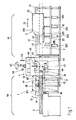
- FIG. 1 shows a processing system according to the invention.
- the Inlet 90 is located to the left of the processing unit 4, the drain region 91 is located to the right thereof.
- a first transport system 1 is provided in the inlet area 90. It serves to a wood workpiece 3, as indicated by on the left to feed into the processing unit 4. The movement the wood workpiece 3 is indicated by the double arrow 30.
- the processing unit 4 not only takes over a processing the front end portion 31, but also serves to, at the indicated by dashed wooden piece of wood 3 'more To provide processing.
- the second transport system 2 On the discharge side 91 is the second transport system 2. This is evidently designed differently than the first one Transport system 1, but without limiting the invention thereto. It is quite possible that on both sides of the Processing units with the same effect and / or the same structure Transport systems are used.
- the second transport system 2 consists of a guideway 21, on which the coupling unit 20 is movable.
- the coupling unit 20 is also referred to as a positioning cart. These two terms are equivalent in the sense of this application.
- the mobility is indicated by the double arrow 22.
- the coupling unit ensures a shape and or non-positive bond with the wood workpiece 3 '.
- the first transport system 1 is driven drive rollers 10 equipped, wherein the wood workpiece 3, for example rests on a machine table or a roller conveyor. so the wood workpiece 3 is transported. It is favorable if the transport unit 1, the top of the wooden workpiece 3 acts, is height adjustable, so as to respect his Conveying effect the different thicknesses of the wood workpiece 3 to be able to adapt. Conveniently, for example, a corresponding arranged vertical guidance, or else the the Drive rollers 10 supporting support beams 12 is rocking or rotating stored (see arrows 13) suspended, thereby ensuring is that at least one drive roller 10 in engagement with the wood workpiece 3 stands. It is also possible endless conveyor, For example, use chain conveyor and the like.
- FIG. 1 Dashed lines in Fig. 1 yet another embodiment shown.
- the two drive beams 19, 19 'are rotatable about the axis of rotation 18 and stored rocking. This axis is horizontal respectively mounted at right angles to the transport direction 30.
- a positioning system with a corresponding Measuring system has.
- the positioning system includes of course the ability to transport the wood workpiece 3 as well as means to recognize that the desired position has been taken is. In general, this is done by an appropriate Normalization or initialization at the beginning of the work and achieved a displacement measurement, reducing the relative position of the positioning system regarding a corresponding indexing, Initialization or normalization point is set and thereby also the location of the wood workpiece 3 on the processing plant is exactly determinable. It is for example provided that the measuring system of a rolling on the wooden workpiece Measuring wheel 11 is formed. The measuring wheel is part of that of the first transport system 1 associated measuring system.
- Fig. 1 are two variants of the arrangement of the devisrades 11, 11 'shown.
- a first variant is the measuring wheel 11 '(shown in dashed lines) directly under the drive wheel 10'.
- the measuring wheel 11 is located in the processing unit as close as possible to the processing unit.
- the measuring wheel rolls as slippery as possible on the surface of the Wood off.
- the measuring wheel 11 in the region of the processing unit 4 is provided, since in particular the location of Wood workpiece 3 with respect to the processing unit 4 for an exact positioning of interest is.
- the measuring system in the guideway 21 or in the coupling unit 20 realized and well known from the prior art.
- the processing unit 4 is, as shown here, with two Tools 41, 42 equipped.
- the term tool not as a single tool to understand, but can certainly also include a tool group or tool type.
- a processing unit 4 is proposed which at least two different tools 41, 42 of which a first tool 41 is above the wood workpiece 3 and a second tool 42 under the wood workpiece. 3 is stored.
- the inventive method or The processing system does not need to be so complex equipped processing unit, but this is considered appropriate higher quality machining is an advantage.
- the first tool 41 led like a portal 40 is. This is a movement perpendicular to the sheet level (Y-axis) possible. It can therefore appropriate positioning for the saw blade formed as the first tool 41st be approached.
- the saw can do a Z-stroke, she is lowered or liftable.
- the saw also rotatable or tiltable.
- the second tool 42 is in the embodiment shown here arranged below the wood workpiece 3. This is For example, provided a stand-like storage. Both that first tool 41 as well as the second tool 42 are in the Vertical movable, which in each case by the double arrows 43 is indicated. This movement can be separated or also be done together, this is not the invention firmly.
- the tools 41, 42 rotate or are designed tiltable.
- the circular saw blade 41 is rotatable about a vertical axis
- the pivotability is indicated by the reference numeral 44.
- the bowing is marked with the reference numeral 45.
- the Arrangement is shown as an example for the upper tool 41, but equally applies to the lower tool 42.
- the tools 41, 42 for example a transverse stroke 46, here at right angles to the transport direction 30 of the workpiece is able to perform.
- the movement of the lower and upper tool with each other be carried out separately or coupled.
- each drive axle has its own drive necessary, the coupled design leads to a not too comfortable solution, but uses the final drive for two tools.
- the first tool 41 is as Saw formed and the second tool 42 is of drilling or Milling tools formed.
- This arrangement is especially in Operation of advantage, as separated from the saw pieces of wood at this variant of the invention easily fall down and so do not hinder the transport of the wood workpiece 3.
- the second transport system 2 It consists of a positioning trolley or a coupling unit 20, which on a guideway 21 is displaceable.
- the coupling unit has two cooperating with each other Pliers parts 25, 26 on.
- at least one of the pliers parts movable about the rotation axis 201 is formed (see arrow 27) and the two pliers parts 25, 26 grasp the wood workpiece 3 above and below.
- the in the Drawing indicated position detects the dashed lines shown Wood workpiece 3 '.
- the arrangement is chosen so that the pliers parts 25, 26, the wood workpiece 3 side, if necessary to take along the entire woodwork length can. This will set the maximum length of a work to be done Workpiece not limited.
- the coupling unit moves the coupling unit to another location, preferably in the direction of the processing unit, where then the pliers the wood workpiece capture again.
- Fig. 1 is a wood workpiece 3 '' shown, which extends over the right End of the processing plant extends beyond. The arrangement is chosen so that nevertheless a transport, as vorilderert, is possible.
- any train rides possible are, that is, the movements of the tools 41, 42 freely combinable are with the transport movement, being the transport movement the wood workpiece 3 either from the first transport system 1 and / or originate from the second transport system 2 like.
- the pliers part 26 from above shown.
- the pliers part is angled double-L or Z-like, the front area, which with the wood workpiece 3 interacts, lies on this and the rear area where the Pliers part 26 is mounted on the coupling element 20, laterally next to the wood workpiece is arranged to cause a collision avoid.
- the pliers part 26 is rotatable about the axis 201. It are drives for the pliers part 26 provided for a secure composite of the pliers part 26 with the wood workpiece.
- fixations or tensioners are provided, for example, if a stationary processing (for example Caps) should take place.
- a stationary processing for example Caps
- the pliers parts 25, 26 act positively and / or positively together with the wood workpiece.
- a wood workpiece 3 is in the inlet area 90 on the processing plant given up.
- the wood workpiece 3 is from the first Transport system 1 and taken in the processing unit. 4 conveyed.
- the first transport system 1 has a measuring system on, the associated measuring wheel 11 comes into engagement with the wood workpiece 3 and determines the appropriate position.
- the wood workpiece 3 is now indexed, for example (for example a light barrier or the like) or to a cross saw be transported in order to learn there a cross-section. To This time it is advantageous if the positioning system either the first or the second or both transport systems normalized or initialized, since now a defined position of the wood workpiece 3 in the processing unit 4 present.
- Processing unit 4 only have a tool 41, which optionally also has performed the Kapp Songs. conveniently, but has the processing unit 4 a variety different tools, according to complex machining operations to allow. It is favorable that the various Machining tools along several translatory axes (which if possible should form a Carthaginian system) are movable and possibly in exploitation of the transport movement the wood workpiece also longitudinal processing done can.
- the processing system is optimized so that either the first transport system 1 or the second transport system 2 or both transport systems together a movement and guide the wood workpiece through the processing unit Afford.
- the second transport system pulls 2 with the help of the coupling unit 20, the wood workpiece 3 'completely out of the processing unit and sets the wood workpiece 3 on a support table 92 in the drainage area 91 off.
- a pusher provided, which is the wood workpiece 3 at right angles to its longitudinal extent wegschiebt, wherein the Pusher under the transport system 2 moves collision-free.
- the wood workpiece 3 can be removed.
- the second transport system drives back again or drives towards the workpiece.
- the transport areas of the first and second transport system 1, 2 in the area of the processing unit 4 connect each other or partially overlap.
- these two overlap Transport areas of the first and second transport system such as this, for example, with the claw or pincer configuration of the coupling element 20 is provided to a secure Take over the wood workpiece 3 in the processing unit. 4 to reach.
- a support table 92 is shown is considerably below the pliers parts 25. Furthermore are Pads 202 are shown, which are lowerable (double arrow 203). The Pads 202 are removable, whereby the wood workpiece so far falls down that the movement of the coupling element 20 is not is hampered.
- the stops 202 are formed here lowerable, but they can also be moved aside to the side to achieve the same result.
- a task cross conveyor is provided, the the wooden workpieces conveyed.
- the wooden workpieces placed on a table parallel to each other, from which then the wooden workpieces in the processing plant be transported and separated.
- the support cross conveyor for example, designed as a conveyor chain is.
- the Einzieher are doing a stop in the transport of Support cross conveyor brought, whereby the wood workpiece to the Puller is aligned.
- the feeders grab that Wood workpiece and promote this in the area of the first Transport system, from which it then for onward transport is taken over.
- the processing plant owns in this area rolls, which is a rolling of the wood workpiece in Allow conveying direction of the transport system. This facilitates the transport of large, heavy wood pieces.
- the support cross conveyor on the wood workpiece promotes a stop or a stop rail
- the first Transport system in the conveying direction of the support transverse conveyor before the stop or the stop rail is arranged and the first transport system transports a wood workpiece, as soon as it rests against the stop / stop rail.
- On a roller conveyor in the conveying direction of the transport system is omitted here.
- Such an arrangement is for example in relatively light pieces of wood such as individual Boards and so on beneficial. The occurring friction force does not lead to a blockage of the transport system.
- the feed cross conveyor promotes continuously the wood work pieces and a removed wood workpiece already gives the stop rail again or the stop free to do that next, second wooden work piece to bring into position.
- the speed Such a processing plant increases accordingly. It is an aspect of the invention, the processing plant designed to be as time-optimized as possible, ie at every processing step Processing times, idle strokes and so on save to achieve the fastest possible processing.
- the width of the drive roller, -rad, or roller is less than the smallest width of the machined Wooden workpiece. This ensures that only a piece of wood is actually singulated and in the processing plant is withdrawn.
- the width of the roll is sufficient not enough, to two parallel wooden pieces of wood to seize and promote.
Landscapes
- Engineering & Computer Science (AREA)
- Mechanical Engineering (AREA)
- Life Sciences & Earth Sciences (AREA)
- Wood Science & Technology (AREA)
- Forests & Forestry (AREA)
- Dovetailed Work, And Nailing Machines And Stapling Machines For Wood (AREA)
Abstract
Description
- Fig. 1
- eine Seitenansicht der erfindungsgemäßen Bearbeitungsanlage und
- Fig. 2
- ein Detail der erfindungsgemäßen Bearbeitungsanlage.
Claims (27)
- Verfahren zum Bearbeiten von Holzwerkstücken, Kanthölzern, Brettern und dergleichen in einer Bearbeitungsanlage, wobei mindestens ein Bearbeitungsaggregat vorgesehen ist, in dessen Zulauf- und Ablaufbereich je ein Transportsystem für das Holzwerkstück vorgesehen ist, wobei gegebenenfalls mindestens ein Transportsystem auch ein Positioniersystem für das Holzwerkstück aufweist und das Bearbeitungsaggregat gegebenenfalls neben einer Bearbeitung des vorderen Endbereiches des Holzwerkstückes auch weitere Bearbeitungen an dem Holzwerkstück ausführt.
- Verfahren nach Anspruch 1, dadurch gekennzeichnet, daß das Positioniersystem beziehungsweise ein damit verbundenes Meßsystem während der ersten Bearbeitung des Holzwerkstückes durch das Bearbeitungsaggregat auf die jeweilige Lage des Transportsystemes zum Holzwerkstück normiert wird und/oder das Transportsystem das Holzwerkstück vor einer Bearbeitung erkennt, erfaßt oder indexiert und so die jeweilige Lage des Transportsystemes zum Holzwerkstück normiert wird.
- Verfahren nach einem oder mehreren der vorhergehenden Ansprüche, dadurch gekennzeichnet, daß die Positioniersysteme beider Transportsysteme normiert werden und/oder die Positioniersysteme synchronisierbar sind.
- Verfahren nach einem oder mehreren der vorhergehenden Ansprüche, dadurch gekennzeichnet, daß während der weiteren Bearbeitung das Holzwerkstück sowohl von dem ersten wie auch von dem zweiten Transportsystem sowie von beiden Transportsystemen in dem Bearbeitungsaggregat positioniert wird und/oder das Holzwerkstück während seiner Bewegung durch das erste und/oder das zweite Transportsystem durch das Bearbeitungsaggregat bearbeitet wird, und so ein Bahnfahren ermöglicht und/oder das Holzwerkstück vor der Bearbeitung, zumindest vor der ersten Bearbeitung, fixiert wird.
- Bearbeitungsanlage zum Bearbeiten von Holzwerkstücken, Kanthölzer, Bretter, Brettstapel und dergleichen, wobei in einem Zulaufbereich ein erstes Transportsystem für das Holzwerkstück vorgesehen ist, welches eingeförderte Holzwerkstücke an ein Bearbeitungsaggregat herantransportiert und wobei auf der Ablaufseite des Bearbeitungsaggregates ein zweites Transportsystem vorgesehen ist, dadurch gekennzeichnet, daß das erste und/oder das zweite Transportsystem (1, 2) das Holzwerkstück (3) für oder während weiterer Bearbeitungen des Bearbeitungsaggregates (4) transportiert.
- Bearbeitungsanlage nach dem vorhergehenden Anspruch 5, dadurch gekennzeichnet, daß sich die Transportbereiche (90, 91) des ersten und des zweiten Transportsystemes (1, 2) im Bereich des Bearbeitungsaggregates (4) einander anschließen oder teilweise überlappen.
- Bearbeitungsanlage nach einem oder beiden der vorhergehenden Ansprüche 5 und 6, dadurch gekennzeichnet, daß zumindest ein Transportsystem ein, mit einem Meßsystem zusammenwirkendes Positioniersystem aufweist, wodurch eine maßgenaue Positionierung und/oder Bahnfahren des Holzwerkstückes (3) in dem Bearbeitungsaggregat (4) möglich ist und/oder das Transportsystem eine kraftund/oder formschlüssig wirkende Kopplungseinheit (20) aufweist, durch welche das Transportsystem (2) mit dem Holzwerkstück (3) für Transport-, Bahnfahr- beziehungsweise Positionierzwecke verbunden ist.
- Bearbeitungsanlage nach einem oder mehreren der vorhergehenden Ansprüche 5 bis 7, dadurch gekennzeichnet, daß das erste Transportsystem (1) von einer/m, zwei oder mehreren angetriebenen Antriebsrolle/n, -rad/rädern (10) oder -walze/n gebildet ist, welche das auf einem Maschinentisch oder einer Rollenbahn aufliegende Holzwerkstück (3) transportiert.
- Bearbeitungsanlage nach einem oder mehreren der vorhergehenden Ansprüche 5 bis 8, dadurch gekennzeichnet, daß ein Tragbalken (12) vorgesehen ist, welcher insbesondere an seinem jeweiligen Balkenende eine/ein oder mehrere Antriebsrolle/n, -rad/räder (10) oder -walze/n trägt.
- Bearbeitungsanlage nach einem oder mehreren der vorhergehenden Ansprüche 5 bis 9, dadurch gekennzeichnet, daß sich der Tragbalken (12) parallel zur Transportrichtung (30) erstreckt und/oder der Tragbalken wippend oder drehbar, insbesondere mittig um eine horizontal oder rechtwinklig zur Transportrichtung orientierte Achse gelagert ist.
- Bearbeitungsanlage nach einem oder mehreren der vorhergehenden Ansprüche 5 bis 10, dadurch gekennzeichnet, daß mindestens ein Antriebsbalken (19) vorgesehen ist, welcher an einem Ende eine Antriebsrolle, -rad oder -walze trägt, wobei der Antriebsbalken (19, 19') wippend beziehungsweise drehbar am anderen Ende um eine horizontal oder rechtwinklig zur Transportrichtung orientierte Achse (201) gelagert ist und/oder zwei voneinander unabhängige Antriebsbalken (19, 19') vorgesehen sind.
- Bearbeitungsanlage nach einem oder mehreren der vorhergehenden Ansprüche 5 bis 11, dadurch gekennzeichnet, daß das Transportsystem (2) von einem längs einer Führungsbahn (21) verfahrbaren Kopplungseinheit (22) gebildet ist.
- Bearbeitungsanlage nach einem oder mehreren der vorhergehenden Ansprüche 5 bis 12, dadurch gekennzeichnet, daß das Bearbeitungsaggregat (4) mindestens ein Werkzeug (41) aufweist, welches zumindest entlang einer Achse, welche bevorzugt rechtwinklig zur Transportrichtung des Transportsystemes ist, beweg- beziehungsweise positionierbar ist und während der Bearbeitung ein Bahnfahren durch Überlagerung der Bewegung des Holzwerkstückes (3) durch das Transportsystem (1, 2) mit der Bewegung des Werkzeuges (41) vorgesehen ist.
- Bearbeitungsanlage nach einem oder mehreren der vorhergehenden Ansprüche 5 bis 13, dadurch gekennzeichnet, daß das Meßsystem von einem auf dem Holzwerkstück (3) abrollenden Meßrad (11) gebildet ist.
- Bearbeitungsanlage nach einem oder mehreren der vorhergehenden Ansprüche 5 bis 14, dadurch gekennzeichnet, daß sich das Meßrad (11') unterhalb der/s Antriebsrades, - rolle oder -walze (10) befindet und/oder das Meßrad (11) im Bereich des Bearbeitungsaggregates (4) vorgesehen ist.
- Bearbeitungsanlage nach einem oder mehreren der vorhergehenden Ansprüche 5 bis 15, gekennzeichnet durch einen kurzen Abstand zwischen dem/r Antriebsrad, -rolle oder - walze und dem Bearbeitungsaggregat beziehungsweise dem Werkzeug (41, 42).
- Bearbeitungsanlage nach einem oder mehreren der vorhergehenden Ansprüche 5 bis 16, dadurch gekennzeichnet, daß in der Führungsbahn (21) und der darauf laufenden Kopplungseinheit (20) ein Meßsystem vorgesehen ist.
- Bearbeitungsanlage nach einem oder mehreren der vorhergehenden Ansprüche 5 bis 17, dadurch gekennzeichnet, daß im Ablaufbereich (91) das fertig bearbeitete Holzwerkstück (3) auf einem gegebenenfalls absenkbaren Auflagetisch (92) oder auf absenkbaren oder wegbewegbaren Auflagen (202) abgelegt wird und ein Abschieber das Holzwerkstück (3) im Wesentlichen rechtwinklig zu seiner Längserstreckung wegschiebt und der Abschieber unter dem Transportsystem (2) kollisionsfrei verfährt.
- Bearbeitungsanlage nach einem oder mehreren der vorhergehenden Ansprüche 5 bis 18, dadurch gekennzeichnet, daß im Ablaufbereich (91) mehrere, bei Bedarf absenkbare Auflagen (202) vorgesehen sind und/oder das Holzwerkstück bei Bedarf soweit absenkbar ist, daß ein Kopplungswagen (10) kollisionsfrei verfährt und/oder im Zulaufbereich ein Aufgabequerförderer vorgesehen ist, der die Holzwerkstücke anfördert.
- Bearbeitungsanlage nach einem oder mehreren der vorhergehenden Ansprüche 5 bis 19, dadurch gekennzeichnet, daß an dem Aufgabequerförderer ein oder mehrere Einzieher vorgesehen sind, an welche/n die Holzwerkstücke herantransportiert und ausgerichtet werden, der/die Einzieher das ausgerichtete Holzwerkstück dann ergreift/en und einzieht/en und dann das erste Transportsystem das zweite Holzwerkstück weitertransportiert und/oder der Aufgabequerförderer das Holzwerkstück an einen Anschlag oder eine Anschlagschiene fördert, und das erste Transportsystem in Förderrichtung des Aufgabenquerförderers vor dem Anschlag/der Anschlagschiene angeordnet ist, und das erste Transportsystem ein Holzwerkstück weitertransportiert sobald dieses am Anschlag/der Anschlagschiene anliegt und/oder die Breite der/s Antriebsrolle, -rades oder -walze geringer ist als die geringste Breite des zu bearbeitenden Holzwerkstückes.
- Bearbeitungsaggregat, insbesondere für eine Bearbeitungsanlage nach einem oder mehreren der vorhergehenden Ansprüche 5 bis 20, für die Bearbeitung von Holzwerkstücken, wobei das Bearbeitungsaggregat mindestens zwei verschiedene Werkzeuge (41, 42) aufweist, wobei ein erstes Werkzeug (41) über dem Holzwerkstück (3) und ein zweites Werkzeug (42) unter dem Holzwerkstück (3) gelagert ist.
- Bearbeitungsaggregat nach dem vorhergehenden Anspruch 21, dadurch gekennzeichnet, daß eine Säge als Werkzeug (41) beziehungsweise spanende Werkzeuge (42) vorgesehen sind und/oder das erste oder zweite Werkzeug (41) von einer Säge und das zweite oder erste Werkzeug (42) von Bohr-, Fräs-, Hobel-, Beschriftungs-, Markier- oder Sonderwerkzeugen gebildet ist und/oder die ersten und zweiten Werkzeuge (41, 42), jeweils unabhängig voneinander oder gemeinsam gekoppelt, zumindest entlang einer Achse, welche insbesondere rechtwinklig zur Transportrichtung angeordnet ist, beweglich und auch steuerbar positionierbar sind und eine Bewegung des Werkzeuges (41, 42) während der Bearbeitung vorgesehen ist und/oder die Werkzeuge (41, 42) dreh- beziehungsweise neigbar ausgebildet sind.
- Bearbeitungsaggregat nach einem oder beiden der vorhergehenden Ansprüche 21 und 22, dadurch gekennzeichnet, daß das erste Werkzeug (41) portalartig und/oder über dem Holzwerkstück geführt ist und/oder das zweite Werkzeug (42) unter dem Sägeblatt gelagert ist.
- Bearbeitungsaggregat nach einem oder mehreren der vorhergehenden Ansprüche 21 bis 23, dadurch gekennzeichnet, daß die Werkzeuge (41, 42) in einem Werkzeugmagazin, auf einem Werkzeugschlitten, insbesondere die zweiten Werkzeuge (42) in einem drehbar gelagerten Werkzeugrevolver vorgehalten werden und/oder die Werkzeuge (41, 42) auf einem Werkzeugschlitten angeordnet sind.
- Transportsystem, insbesondere für eine Bearbeitungsanlage nach einen oder mehreren der vorhergehenden Ansprüche 5 bis 20, wobei das Transportsystem für einen Transport und gegebenenfalls auch Positionierung des Holzwerkstückes dient und das Transportsystem eine längs einer Führungsbahn verfahrbare Kopplungseinheit aufweist, dadurch gekennzeichnet, daß die Kopplungseinheit (20) zwei zusammenwirkenden Zangenteilen (25, 26) aufweist, bei welchen zumindest eines beweglich ausgebildet ist und die beiden Zangenteile (25, 26) das Holzwerkstück (3) oben und unten ergreifen.
- Transportsystem nach dem vorhergehenden Anspruch 25, dadurch gekennzeichnet, daß die Zangenteile (25, 26) länglich ausgebildet sind und sich parallel zur Transportrichtung (22) erstrecken und/oder die Zangenteile (25, 26) das Holzwerkstück seitlich, entlang der gesamten Holzwerkstücklänge zu ergreifen vermag und/oder bei einem Weitertransport des Holzwerkstückes die Zangenteile das Holzwerkstück freigeben, die Kopplungseinheit an eine andere Stelle, bevorzugt in Richtung des Bearbeitungsaggregates, verfährt, und dort das Holzwerkstück wieder erfaßt wird.
- Transportsystem nach einem oder beiden der vorhergehenden Ansprüche 25 und 26, dadurch gekennzeichnet, daß die Zangenteile (25, 26) kraft- und/oder formschlüssig mit dem Holzwerkstück (3) zusammenwirken und/oder das Zangenteil backenartig oder schneidenartig ausgebildet ist.
Applications Claiming Priority (4)
| Application Number | Priority Date | Filing Date | Title |
|---|---|---|---|
| DE10246288 | 2002-10-02 | ||
| DE10246288 | 2002-10-02 | ||
| DE10305570 | 2003-02-10 | ||
| DE10305570.3A DE10305570B4 (de) | 2002-10-02 | 2003-02-10 | Verfahren und Bearbeitungsanlage für das Bearbeiten von Holzwerkstücken |
Publications (3)
| Publication Number | Publication Date |
|---|---|
| EP1405693A2 true EP1405693A2 (de) | 2004-04-07 |
| EP1405693A3 EP1405693A3 (de) | 2008-04-16 |
| EP1405693B1 EP1405693B1 (de) | 2017-04-26 |
Family
ID=31995072
Family Applications (1)
| Application Number | Title | Priority Date | Filing Date |
|---|---|---|---|
| EP03022095.8A Expired - Lifetime EP1405693B1 (de) | 2002-10-02 | 2003-10-02 | Bearbeitungsanlage für das Bearbeiten von Holzwerkstücken |
Country Status (3)
| Country | Link |
|---|---|
| US (1) | US7661451B2 (de) |
| EP (1) | EP1405693B1 (de) |
| DE (1) | DE10305570B4 (de) |
Cited By (13)
| Publication number | Priority date | Publication date | Assignee | Title |
|---|---|---|---|---|
| ITMC20090113A1 (it) * | 2009-05-15 | 2010-11-16 | Erregi Di Giunti Renzo | Macchina e procedimento per la realizzazione di pannelli forati. |
| ITFI20100156A1 (it) * | 2010-07-26 | 2012-01-27 | Vitap Costruzioni Meccaniche S P A | Macchina foratrice a controllo numerico per pannelli in legno con dispositivo di trascinamento perfezionato |
| WO2013104706A1 (de) * | 2012-01-14 | 2013-07-18 | Hans Hundegger | Holzbearbeitungsanlage und verfahren zu deren betrieb |
| EP3069837A1 (de) * | 2015-03-16 | 2016-09-21 | Homag Holzbearbeitungssysteme GmbH | Bearbeitungsvorrichtung |
| ITFI20150133A1 (it) * | 2015-05-08 | 2016-11-08 | Vitap Costruzioni Mecc S P A | Macchina a controllo numerico per la lavorazione di pannelli in legno con dispositivo di trascinamento perfezionato |
| EP3453488A1 (de) * | 2017-09-06 | 2019-03-13 | Hans Hundegger | Plattenbearbeitungsanlage |
| CN109591115A (zh) * | 2018-12-25 | 2019-04-09 | 苏军 | 一种板材高速边缘加工机 |
| EP3539740A1 (de) | 2018-03-16 | 2019-09-18 | Algemene Machinebouw De Muynck NV | Verbesserte vorrichtung zur bearbeitung eines strahls |
| CN111844268A (zh) * | 2020-07-14 | 2020-10-30 | 江西圭元家具有限公司 | 一种实木加工柔性生产线 |
| IT202000008404A1 (it) * | 2020-04-20 | 2021-10-20 | Cms Spa | Macchina bifronte di lavorazione industriale. |
| WO2022049117A1 (de) * | 2020-09-04 | 2022-03-10 | Homag Gmbh | Bearbeitungseinrichtung und verfahren zum längsprofilieren von werkstücken |
| EP4331794A1 (de) * | 2022-09-01 | 2024-03-06 | Hans Hundegger Beteiligungs GmbH & Co. KG | Plattenbearbeitungsanlage |
| EP4405145A4 (de) * | 2021-09-20 | 2025-02-19 | Weisshaus Research Pty Ltd | Dickenhobelmaschine |
Families Citing this family (17)
| Publication number | Priority date | Publication date | Assignee | Title |
|---|---|---|---|---|
| US7950316B2 (en) * | 2005-06-28 | 2011-05-31 | Mitek Holdings, Inc. | Automated system for precision cutting short pieces of lumber |
| ITBO20070558A1 (it) * | 2007-08-03 | 2009-02-04 | Biesse Spa | Macchina per la lavorazione di componenti di legno o simili, in particolare componenti per infissi |
| ITBO20080623A1 (it) * | 2008-10-10 | 2010-04-11 | Biesse Spa | Macchina per la separazione di componenti da pannelli di legno o simili |
| RU2471613C1 (ru) * | 2011-05-05 | 2013-01-10 | Российская Федерация, от имени которой выступает Министерство промышленности и торговли | Продольно-фрезерный деревообрабатывающий станок |
| GB2492347A (en) * | 2011-06-28 | 2013-01-02 | Nicholas Timothy Showan | Building method, cutting apparatus and liquid-laden foam insulator |
| JP5759361B2 (ja) * | 2011-12-27 | 2015-08-05 | 株式会社アマダホールディングス | 帯鋸盤及び帯鋸盤の制御方法 |
| WO2014074023A2 (ru) * | 2012-11-12 | 2014-05-15 | Oparin Vladimir Vladimirovich | Станок для обработки изделий из древесины поперек волокон в трех плоскостях различных поперечных сечений |
| DE102014006740B4 (de) * | 2014-05-12 | 2020-10-29 | Ima Schelling Deutschland Gmbh | Bearbeitungsmaschine mit Manipulationsvorrichtung zur Bearbeitung plattenförmiger Werkstücke |
| CN105750619A (zh) * | 2015-06-25 | 2016-07-13 | 中山佑腾电子科技有限公司 | 一种伺服切管机 |
| CN105750626A (zh) * | 2015-06-25 | 2016-07-13 | 中山佑腾电子科技有限公司 | 一种自动切管机 |
| CN105750621A (zh) * | 2015-06-25 | 2016-07-13 | 中山佑腾电子科技有限公司 | 一种带切口冷却装置的切管机 |
| CN105750620A (zh) * | 2015-06-25 | 2016-07-13 | 中山佑腾电子科技有限公司 | 一种旋转切口式切管机 |
| CN105750623A (zh) * | 2015-06-25 | 2016-07-13 | 中山佑腾电子科技有限公司 | 一种带进料口自动分料功能的切管机 |
| CN105750622A (zh) * | 2015-06-25 | 2016-07-13 | 中山佑腾电子科技有限公司 | 一种带管体固定装置的切管机 |
| CN106881478B (zh) * | 2017-03-10 | 2018-12-25 | 杭州凯贝奈特科技有限公司 | 一种机箱外壳钻孔机构及机箱装配系统 |
| IT202000024955A1 (it) * | 2020-10-22 | 2022-04-22 | Lorenzo Lattanzi | Metodo e macchina per la realizzazione di componenti di legno o simili |
| BE1029397B1 (de) * | 2021-05-11 | 2022-12-12 | Phoenix Contact Gmbh & Co | Werkzeugmaschine zur Herstellung eines Werkstücks vordefinierter Länge |
Family Cites Families (34)
| Publication number | Priority date | Publication date | Assignee | Title |
|---|---|---|---|---|
| US3327747A (en) * | 1965-10-24 | 1967-06-27 | Weyerhaeuser Co | Method of and apparatus for kerfless cutting of wood |
| US3223131A (en) * | 1961-03-17 | 1965-12-14 | Roy M Hovermale | Apparatus for forming transversely reinforced wood planks |
| US3241583A (en) * | 1962-12-26 | 1966-03-22 | Wurlitzer Co | Tandem station machine for making piano action parts |
| CH515485A (de) * | 1970-02-10 | 1971-11-15 | Intercont Ferromatic Trust Reg | Einrichtung zum Ablängen und zur Bestimmung mindestens einer Querabmessung langgestreckter Werkstücke |
| US3833033A (en) * | 1969-04-17 | 1974-09-03 | Hurn Brothers Eng Ltd | Method and apparatus for working elongate components at successive longitudinal locations |
| DE2518145A1 (de) * | 1975-04-24 | 1976-11-04 | Franz Kampmeier | Bearbeitungsvorrichtung fuer holzplatten oder -bretter |
| CA1027461A (en) * | 1976-02-13 | 1978-03-07 | J. Kenneth Seaman | Method and apparatus for cutting wood |
| SE398067B (sv) * | 1976-04-07 | 1977-12-05 | Saab Scania Ab | Sett och anordning for att hantera vankantade bredor |
| US4098310A (en) * | 1977-03-14 | 1978-07-04 | Arthur Carol Sanford | Apparatus for beveling truss components |
| US4210184A (en) * | 1978-01-30 | 1980-07-01 | Producto Machinery Corporation | Circular resaw apparatus and method |
| US4378035A (en) * | 1978-07-17 | 1983-03-29 | Chisum Finis L | Machine to prepare logs for log houses |
| FI67317C (fi) * | 1980-11-14 | 1985-03-11 | Ahlstroem Oy | Anordning foer inriktning av ett saogvarustycke i synnerhet et block |
| SE435348B (sv) * | 1983-02-17 | 1984-09-24 | Osa Ab | Forfarande och anordning vid kapning av tredstammar i bestemda lengder |
| DE3420080C1 (de) * | 1984-05-29 | 1989-11-02 | Konrad 8011 Faistenhaar Frey | Abbundmaschine zum Bearbeiten von Brettern,Kanthoelzern und dergleichen |
| DE3607980A1 (de) * | 1986-03-11 | 1987-09-17 | Linck Masch Gatterlinck | Verfahren und vorrichtung zum zufuehren von baumstaemmen zu einer bearbeitungsmaschine |
| DE3741171A1 (de) * | 1987-12-04 | 1989-06-15 | Hans Kuehl | Zimmerei-abbundanlage |
| EP0391945B1 (de) * | 1987-12-15 | 1992-06-17 | Karl Ing. Rumpler | Fertigungseinrichtung |
| CA1265024A (en) * | 1988-08-17 | 1990-01-30 | Ronald A. Wrightman | Machine for cutting logs to form log joints |
| DE3900304A1 (de) * | 1989-01-07 | 1990-07-12 | Okoma Maschf Gmbh | Vorrichtung zum laengsprofilieren von hoelzern |
| US4881584A (en) * | 1989-01-09 | 1989-11-21 | Weyerhaeuser Company | Infeed conveyor for saw |
| DE4208233A1 (de) * | 1992-03-14 | 1993-09-16 | Hans Hundegger | Abbundmaschine zum bearbeiten von kanthoelzern oder dergleichen |
| DE4301217A1 (de) * | 1993-01-19 | 1994-07-21 | Baljer & Zembrod | CNC-gesteuerte Holzbearbeitungsanlage, insbesondere für lange Werkstücke wie Balken |
| DE4301216A1 (de) * | 1993-01-19 | 1994-07-21 | Baljer & Zembrod | Vorrichtung zur Führung der Werkstücke bei einer automatischen Holzbearbeitungsmaschine |
| US5373878A (en) * | 1993-09-02 | 1994-12-20 | Cm Machinery Corporation | Log conveyor for a scragg mill |
| CA2109254C (fr) * | 1993-10-26 | 1997-04-22 | Maurice J. Brisson | Sciage et decoupage d'equarris deux-faces selon leur courbe |
| US5447186A (en) * | 1993-12-20 | 1995-09-05 | Sawquip International, Inc. | Chipping canter |
| AU737810B2 (en) * | 1996-03-21 | 2001-08-30 | Usnr/Kockums Cancar Company | Position-based integrated motion controlled curve sawing |
| GB2328398A (en) * | 1997-08-19 | 1999-02-24 | Jali Ltd | Cutting Machine. |
| DE19920006C2 (de) * | 1998-05-29 | 2002-10-10 | Hans Schmidler | Abbundanlage |
| EP0988924B2 (de) * | 1998-09-25 | 2012-09-05 | Hans Hundegger | Holzbearbeitungsanlage |
| AT406840B (de) * | 1999-02-09 | 2000-09-25 | Wolf Systembau Gmbh & Co Kg | Vorrichtung zum bearbeiten von baumstämmen |
| US6062281A (en) * | 1999-05-13 | 2000-05-16 | U.S. Natural Resources | Vertical arbor saw for shape sawing a log |
| DE19926834C2 (de) * | 1999-06-12 | 2001-03-29 | Weinmann & Partner Gmbh | Vorrichtung zur Bearbeitung länglicher Werkstücke, insbesondere von Holzbalken |
| US6640855B2 (en) * | 2001-09-05 | 2003-11-04 | Hearthstone, Inc. | Log home fabrication process and associate log cutting machine |
-
2003
- 2003-02-10 DE DE10305570.3A patent/DE10305570B4/de not_active Withdrawn - After Issue
- 2003-10-02 EP EP03022095.8A patent/EP1405693B1/de not_active Expired - Lifetime
- 2003-12-08 US US10/728,773 patent/US7661451B2/en not_active Expired - Lifetime
Cited By (18)
| Publication number | Priority date | Publication date | Assignee | Title |
|---|---|---|---|---|
| ITMC20090113A1 (it) * | 2009-05-15 | 2010-11-16 | Erregi Di Giunti Renzo | Macchina e procedimento per la realizzazione di pannelli forati. |
| ITFI20100156A1 (it) * | 2010-07-26 | 2012-01-27 | Vitap Costruzioni Meccaniche S P A | Macchina foratrice a controllo numerico per pannelli in legno con dispositivo di trascinamento perfezionato |
| EP2412500A1 (de) * | 2010-07-26 | 2012-02-01 | Vitap Costruzioni Meccaniche S.p.A. | Eine Holz Bohrmaschine mit einer verbesserten Zuführeinrichtung |
| WO2013104706A1 (de) * | 2012-01-14 | 2013-07-18 | Hans Hundegger | Holzbearbeitungsanlage und verfahren zu deren betrieb |
| US9815164B2 (en) | 2012-01-14 | 2017-11-14 | Hans Hundegger | Wood-working machine and method for the operation thereof |
| EP3069837A1 (de) * | 2015-03-16 | 2016-09-21 | Homag Holzbearbeitungssysteme GmbH | Bearbeitungsvorrichtung |
| ITFI20150133A1 (it) * | 2015-05-08 | 2016-11-08 | Vitap Costruzioni Mecc S P A | Macchina a controllo numerico per la lavorazione di pannelli in legno con dispositivo di trascinamento perfezionato |
| EP3106276A1 (de) * | 2015-05-08 | 2016-12-21 | Vitap Costruzioni Meccaniche S.p.A. | Eine holzbearbeitungsmachine mit einer numerischen steuerung mit einem verbesserten fütterungssystem und eine methode um holzpanele zu bewegen in einer holzbearbeitungsmachine |
| EP3453488A1 (de) * | 2017-09-06 | 2019-03-13 | Hans Hundegger | Plattenbearbeitungsanlage |
| EP3539740A1 (de) | 2018-03-16 | 2019-09-18 | Algemene Machinebouw De Muynck NV | Verbesserte vorrichtung zur bearbeitung eines strahls |
| CN109591115A (zh) * | 2018-12-25 | 2019-04-09 | 苏军 | 一种板材高速边缘加工机 |
| CN109591115B (zh) * | 2018-12-25 | 2021-03-19 | 苏中奕 | 一种板材高速边缘加工机 |
| IT202000008404A1 (it) * | 2020-04-20 | 2021-10-20 | Cms Spa | Macchina bifronte di lavorazione industriale. |
| EP3900901A1 (de) * | 2020-04-20 | 2021-10-27 | C.M.S. S.p.A. | Doppelseitige maschine zur industriellen verarbeitung |
| CN111844268A (zh) * | 2020-07-14 | 2020-10-30 | 江西圭元家具有限公司 | 一种实木加工柔性生产线 |
| WO2022049117A1 (de) * | 2020-09-04 | 2022-03-10 | Homag Gmbh | Bearbeitungseinrichtung und verfahren zum längsprofilieren von werkstücken |
| EP4405145A4 (de) * | 2021-09-20 | 2025-02-19 | Weisshaus Research Pty Ltd | Dickenhobelmaschine |
| EP4331794A1 (de) * | 2022-09-01 | 2024-03-06 | Hans Hundegger Beteiligungs GmbH & Co. KG | Plattenbearbeitungsanlage |
Also Published As
| Publication number | Publication date |
|---|---|
| US7661451B2 (en) | 2010-02-16 |
| DE10305570B4 (de) | 2016-01-28 |
| EP1405693A3 (de) | 2008-04-16 |
| US20050121109A1 (en) | 2005-06-09 |
| DE10305570A1 (de) | 2004-04-15 |
| EP1405693B1 (de) | 2017-04-26 |
Similar Documents
| Publication | Publication Date | Title |
|---|---|---|
| EP1405693B1 (de) | Bearbeitungsanlage für das Bearbeiten von Holzwerkstücken | |
| EP0988924B1 (de) | Holzbearbeitungsanlage | |
| EP0296161B1 (de) | Verfahren und vorrichtung zum zuführen von baumstämmen zu einer bearbeitungsmaschine | |
| EP0922547B1 (de) | Maschine zum Bearbeiten von Fensterrahmen-Holmen | |
| EP0634254A1 (de) | Vorrichtung mit Vorschubwagen und Verfahren zum Herstellen von Holzerzeugnissen aus Stammholz | |
| EP2158055B1 (de) | Sägevorrichtung und verfahren zur sägenden bearbeitung eines werkstücks | |
| EP0217784A1 (de) | Verfahren und Vorrichtung zum Besäumen von Baumstämmen | |
| EP0480191A2 (de) | Vorrichtung zum Bearbeiten von Stangen | |
| DE7015126U (de) | Vorrichtung zum durchfuehren mehrerer arbeiten an bestimmten stellen eines vorzugsweise langgestreckten werkstueckes. | |
| EP4008508A1 (de) | Verfahren zum zersägen zumindest eines werkstücks | |
| DE102006027013B3 (de) | Maschine und Verfahren zum Formatieren von Platten | |
| EP0561227B1 (de) | Abbundmaschine zum Bearbeiten von Kanthölzern oder dergleichen | |
| EP2185331B1 (de) | Vorrichtung zur bearbeitung von werkstücken aus holz, kunststoff und dergleichen sowie verfahren zum bearbeiten von solchen werkstücken | |
| DE19547193C2 (de) | Verfahren und Vorrichtung zum Einschneiden eines Baumstammes | |
| EP0813941B2 (de) | Abbundanlage zur Bearbeitung von Strangmaterial | |
| EP0730516B1 (de) | Einrichtung zur bearbeitung von massivholzwerkstücken in ihrer längsrichtung | |
| DE4212903C2 (de) | ||
| DE4235240C2 (de) | Verfahren zur Herstellung und Bearbeitung paralleler Gehrungen an den beiden Stirnflächen langgestreckter Hölzer und Doppelendprofiler zur Durchführung dieses Verfahrens | |
| DE102007022166A1 (de) | Sägemaschineneinheit und Sägemaschine | |
| DE19963180C2 (de) | Zapfenschneidmaschine zur Bearbeitung von Holzwerkstücken | |
| DE19721521C2 (de) | Numerisch gesteuerte Zapfenschneidmaschine | |
| EP4067028B1 (de) | Zurichtstation und vorrichtung mit einer zurichtstation | |
| DE19907585B4 (de) | Holzbearbeitungsanlage | |
| EP1203645B1 (de) | Verfahren und Vorrichtung zum Zerteilen eines Baumstammes | |
| DE19703240B4 (de) | Vorrichtung zum Handhaben und Bearbeiten von vorzugsweise plattenförmigen Werkstücken |
Legal Events
| Date | Code | Title | Description |
|---|---|---|---|
| PUAI | Public reference made under article 153(3) epc to a published international application that has entered the european phase |
Free format text: ORIGINAL CODE: 0009012 |
|
| AK | Designated contracting states |
Kind code of ref document: A2 Designated state(s): AT BE BG CH CY CZ DE DK EE ES FI FR GB GR HU IE IT LI LU MC NL PT RO SE SI SK TR |
|
| AX | Request for extension of the european patent |
Extension state: AL LT LV MK |
|
| PUAL | Search report despatched |
Free format text: ORIGINAL CODE: 0009013 |
|
| AK | Designated contracting states |
Kind code of ref document: A3 Designated state(s): AT BE BG CH CY CZ DE DK EE ES FI FR GB GR HU IE IT LI LU MC NL PT RO SE SI SK TR |
|
| AX | Request for extension of the european patent |
Extension state: AL LT LV MK |
|
| 17P | Request for examination filed |
Effective date: 20081014 |
|
| AKX | Designation fees paid |
Designated state(s): AT BE BG CH CY CZ DE DK EE ES FI FR GB GR HU IE IT LI LU MC NL PT RO SE SI SK TR |
|
| 17Q | First examination report despatched |
Effective date: 20101221 |
|
| GRAP | Despatch of communication of intention to grant a patent |
Free format text: ORIGINAL CODE: EPIDOSNIGR1 |
|
| INTG | Intention to grant announced |
Effective date: 20161220 |
|
| GRAS | Grant fee paid |
Free format text: ORIGINAL CODE: EPIDOSNIGR3 |
|
| GRAA | (expected) grant |
Free format text: ORIGINAL CODE: 0009210 |
|
| AK | Designated contracting states |
Kind code of ref document: B1 Designated state(s): AT BE BG CH CY CZ DE DK EE ES FI FR GB GR HU IE IT LI LU MC NL PT RO SE SI SK TR |
|
| REG | Reference to a national code |
Ref country code: GB Ref legal event code: FG4D Free format text: NOT ENGLISH |
|
| REG | Reference to a national code |
Ref country code: CH Ref legal event code: EP Ref country code: CH Ref legal event code: NV Representative=s name: LUCHS AND PARTNER AG PATENTANWAELTE, CH |
|
| REG | Reference to a national code |
Ref country code: AT Ref legal event code: REF Ref document number: 887452 Country of ref document: AT Kind code of ref document: T Effective date: 20170515 |
|
| REG | Reference to a national code |
Ref country code: IE Ref legal event code: FG4D Free format text: LANGUAGE OF EP DOCUMENT: GERMAN |
|
| REG | Reference to a national code |
Ref country code: DE Ref legal event code: R096 Ref document number: 50315645 Country of ref document: DE |
|
| REG | Reference to a national code |
Ref country code: NL Ref legal event code: MP Effective date: 20170426 |
|
| REG | Reference to a national code |
Ref country code: FR Ref legal event code: PLFP Year of fee payment: 15 |
|
| PG25 | Lapsed in a contracting state [announced via postgrant information from national office to epo] |
Ref country code: NL Free format text: LAPSE BECAUSE OF FAILURE TO SUBMIT A TRANSLATION OF THE DESCRIPTION OR TO PAY THE FEE WITHIN THE PRESCRIBED TIME-LIMIT Effective date: 20170426 |
|
| PG25 | Lapsed in a contracting state [announced via postgrant information from national office to epo] |
Ref country code: ES Free format text: LAPSE BECAUSE OF FAILURE TO SUBMIT A TRANSLATION OF THE DESCRIPTION OR TO PAY THE FEE WITHIN THE PRESCRIBED TIME-LIMIT Effective date: 20170426 Ref country code: FI Free format text: LAPSE BECAUSE OF FAILURE TO SUBMIT A TRANSLATION OF THE DESCRIPTION OR TO PAY THE FEE WITHIN THE PRESCRIBED TIME-LIMIT Effective date: 20170426 Ref country code: GR Free format text: LAPSE BECAUSE OF FAILURE TO SUBMIT A TRANSLATION OF THE DESCRIPTION OR TO PAY THE FEE WITHIN THE PRESCRIBED TIME-LIMIT Effective date: 20170727 |
|
| PG25 | Lapsed in a contracting state [announced via postgrant information from national office to epo] |
Ref country code: SE Free format text: LAPSE BECAUSE OF FAILURE TO SUBMIT A TRANSLATION OF THE DESCRIPTION OR TO PAY THE FEE WITHIN THE PRESCRIBED TIME-LIMIT Effective date: 20170426 Ref country code: BG Free format text: LAPSE BECAUSE OF FAILURE TO SUBMIT A TRANSLATION OF THE DESCRIPTION OR TO PAY THE FEE WITHIN THE PRESCRIBED TIME-LIMIT Effective date: 20170726 |
|
| REG | Reference to a national code |
Ref country code: DE Ref legal event code: R097 Ref document number: 50315645 Country of ref document: DE |
|
| PG25 | Lapsed in a contracting state [announced via postgrant information from national office to epo] |
Ref country code: SK Free format text: LAPSE BECAUSE OF FAILURE TO SUBMIT A TRANSLATION OF THE DESCRIPTION OR TO PAY THE FEE WITHIN THE PRESCRIBED TIME-LIMIT Effective date: 20170426 Ref country code: EE Free format text: LAPSE BECAUSE OF FAILURE TO SUBMIT A TRANSLATION OF THE DESCRIPTION OR TO PAY THE FEE WITHIN THE PRESCRIBED TIME-LIMIT Effective date: 20170426 Ref country code: DK Free format text: LAPSE BECAUSE OF FAILURE TO SUBMIT A TRANSLATION OF THE DESCRIPTION OR TO PAY THE FEE WITHIN THE PRESCRIBED TIME-LIMIT Effective date: 20170426 Ref country code: RO Free format text: LAPSE BECAUSE OF FAILURE TO SUBMIT A TRANSLATION OF THE DESCRIPTION OR TO PAY THE FEE WITHIN THE PRESCRIBED TIME-LIMIT Effective date: 20170426 Ref country code: CZ Free format text: LAPSE BECAUSE OF FAILURE TO SUBMIT A TRANSLATION OF THE DESCRIPTION OR TO PAY THE FEE WITHIN THE PRESCRIBED TIME-LIMIT Effective date: 20170426 |
|
| PLBE | No opposition filed within time limit |
Free format text: ORIGINAL CODE: 0009261 |
|
| STAA | Information on the status of an ep patent application or granted ep patent |
Free format text: STATUS: NO OPPOSITION FILED WITHIN TIME LIMIT |
|
| 26N | No opposition filed |
Effective date: 20180129 |
|
| PG25 | Lapsed in a contracting state [announced via postgrant information from national office to epo] |
Ref country code: SI Free format text: LAPSE BECAUSE OF FAILURE TO SUBMIT A TRANSLATION OF THE DESCRIPTION OR TO PAY THE FEE WITHIN THE PRESCRIBED TIME-LIMIT Effective date: 20170426 Ref country code: MC Free format text: LAPSE BECAUSE OF FAILURE TO SUBMIT A TRANSLATION OF THE DESCRIPTION OR TO PAY THE FEE WITHIN THE PRESCRIBED TIME-LIMIT Effective date: 20170426 |
|
| GBPC | Gb: european patent ceased through non-payment of renewal fee |
Effective date: 20171002 |
|
| REG | Reference to a national code |
Ref country code: IE Ref legal event code: MM4A |
|
| PG25 | Lapsed in a contracting state [announced via postgrant information from national office to epo] |
Ref country code: GB Free format text: LAPSE BECAUSE OF NON-PAYMENT OF DUE FEES Effective date: 20171002 Ref country code: LU Free format text: LAPSE BECAUSE OF NON-PAYMENT OF DUE FEES Effective date: 20171002 |
|
| REG | Reference to a national code |
Ref country code: BE Ref legal event code: MM Effective date: 20171031 |
|
| PG25 | Lapsed in a contracting state [announced via postgrant information from national office to epo] |
Ref country code: BE Free format text: LAPSE BECAUSE OF NON-PAYMENT OF DUE FEES Effective date: 20171031 |
|
| REG | Reference to a national code |
Ref country code: FR Ref legal event code: PLFP Year of fee payment: 16 |
|
| PG25 | Lapsed in a contracting state [announced via postgrant information from national office to epo] |
Ref country code: IE Free format text: LAPSE BECAUSE OF NON-PAYMENT OF DUE FEES Effective date: 20171002 |
|
| PG25 | Lapsed in a contracting state [announced via postgrant information from national office to epo] |
Ref country code: HU Free format text: LAPSE BECAUSE OF FAILURE TO SUBMIT A TRANSLATION OF THE DESCRIPTION OR TO PAY THE FEE WITHIN THE PRESCRIBED TIME-LIMIT; INVALID AB INITIO Effective date: 20031002 |
|
| PG25 | Lapsed in a contracting state [announced via postgrant information from national office to epo] |
Ref country code: CY Free format text: LAPSE BECAUSE OF NON-PAYMENT OF DUE FEES Effective date: 20170426 |
|
| PG25 | Lapsed in a contracting state [announced via postgrant information from national office to epo] |
Ref country code: TR Free format text: LAPSE BECAUSE OF FAILURE TO SUBMIT A TRANSLATION OF THE DESCRIPTION OR TO PAY THE FEE WITHIN THE PRESCRIBED TIME-LIMIT Effective date: 20170426 |
|
| PG25 | Lapsed in a contracting state [announced via postgrant information from national office to epo] |
Ref country code: PT Free format text: LAPSE BECAUSE OF FAILURE TO SUBMIT A TRANSLATION OF THE DESCRIPTION OR TO PAY THE FEE WITHIN THE PRESCRIBED TIME-LIMIT Effective date: 20170426 |
|
| PGFP | Annual fee paid to national office [announced via postgrant information from national office to epo] |
Ref country code: AT Payment date: 20211019 Year of fee payment: 19 Ref country code: DE Payment date: 20211125 Year of fee payment: 19 |
|
| PGFP | Annual fee paid to national office [announced via postgrant information from national office to epo] |
Ref country code: IT Payment date: 20211029 Year of fee payment: 19 Ref country code: FR Payment date: 20211022 Year of fee payment: 19 Ref country code: CH Payment date: 20211022 Year of fee payment: 19 |
|
| REG | Reference to a national code |
Ref country code: DE Ref legal event code: R119 Ref document number: 50315645 Country of ref document: DE |
|
| REG | Reference to a national code |
Ref country code: CH Ref legal event code: PL |
|
| REG | Reference to a national code |
Ref country code: AT Ref legal event code: MM01 Ref document number: 887452 Country of ref document: AT Kind code of ref document: T Effective date: 20221002 |
|
| PG25 | Lapsed in a contracting state [announced via postgrant information from national office to epo] |
Ref country code: LI Free format text: LAPSE BECAUSE OF NON-PAYMENT OF DUE FEES Effective date: 20221031 Ref country code: FR Free format text: LAPSE BECAUSE OF NON-PAYMENT OF DUE FEES Effective date: 20221031 Ref country code: DE Free format text: LAPSE BECAUSE OF NON-PAYMENT OF DUE FEES Effective date: 20230503 Ref country code: CH Free format text: LAPSE BECAUSE OF NON-PAYMENT OF DUE FEES Effective date: 20221031 Ref country code: AT Free format text: LAPSE BECAUSE OF NON-PAYMENT OF DUE FEES Effective date: 20221002 |
|
| PG25 | Lapsed in a contracting state [announced via postgrant information from national office to epo] |
Ref country code: IT Free format text: LAPSE BECAUSE OF NON-PAYMENT OF DUE FEES Effective date: 20221002 |