EP1402156B1 - Dispositif de separation d'huile pour gaz de carter de vilebrequin de moteur a combustion interne - Google Patents
Dispositif de separation d'huile pour gaz de carter de vilebrequin de moteur a combustion interne Download PDFInfo
- Publication number
- EP1402156B1 EP1402156B1 EP02729799A EP02729799A EP1402156B1 EP 1402156 B1 EP1402156 B1 EP 1402156B1 EP 02729799 A EP02729799 A EP 02729799A EP 02729799 A EP02729799 A EP 02729799A EP 1402156 B1 EP1402156 B1 EP 1402156B1
- Authority
- EP
- European Patent Office
- Prior art keywords
- separation device
- oil
- cylinder head
- head cover
- housing half
- Prior art date
- Legal status (The legal status is an assumption and is not a legal conclusion. Google has not performed a legal analysis and makes no representation as to the accuracy of the status listed.)
- Expired - Lifetime
Links
- 239000007789 gas Substances 0.000 title claims description 26
- 238000002485 combustion reaction Methods 0.000 title claims description 13
- 238000000926 separation method Methods 0.000 claims description 55
- 238000007789 sealing Methods 0.000 claims description 4
- 239000003921 oil Substances 0.000 description 27
- 239000007788 liquid Substances 0.000 description 16
- 230000002093 peripheral effect Effects 0.000 description 6
- 239000000470 constituent Substances 0.000 description 2
- 238000010276 construction Methods 0.000 description 2
- 230000005484 gravity Effects 0.000 description 2
- 238000010992 reflux Methods 0.000 description 2
- 230000006978 adaptation Effects 0.000 description 1
- 230000015572 biosynthetic process Effects 0.000 description 1
- 238000009835 boiling Methods 0.000 description 1
- 238000000151 deposition Methods 0.000 description 1
- 230000000694 effects Effects 0.000 description 1
- 229930195733 hydrocarbon Natural products 0.000 description 1
- 150000002430 hydrocarbons Chemical class 0.000 description 1
- 239000004615 ingredient Substances 0.000 description 1
- 238000002347 injection Methods 0.000 description 1
- 239000007924 injection Substances 0.000 description 1
- 238000004519 manufacturing process Methods 0.000 description 1
- 230000013011 mating Effects 0.000 description 1
- 239000010705 motor oil Substances 0.000 description 1
Images


Classifications
-
- F—MECHANICAL ENGINEERING; LIGHTING; HEATING; WEAPONS; BLASTING
- F01—MACHINES OR ENGINES IN GENERAL; ENGINE PLANTS IN GENERAL; STEAM ENGINES
- F01M—LUBRICATING OF MACHINES OR ENGINES IN GENERAL; LUBRICATING INTERNAL COMBUSTION ENGINES; CRANKCASE VENTILATING
- F01M13/00—Crankcase ventilating or breathing
- F01M13/04—Crankcase ventilating or breathing having means for purifying air before leaving crankcase, e.g. removing oil
- F01M13/0416—Crankcase ventilating or breathing having means for purifying air before leaving crankcase, e.g. removing oil arranged in valve-covers
-
- F—MECHANICAL ENGINEERING; LIGHTING; HEATING; WEAPONS; BLASTING
- F01—MACHINES OR ENGINES IN GENERAL; ENGINE PLANTS IN GENERAL; STEAM ENGINES
- F01M—LUBRICATING OF MACHINES OR ENGINES IN GENERAL; LUBRICATING INTERNAL COMBUSTION ENGINES; CRANKCASE VENTILATING
- F01M13/00—Crankcase ventilating or breathing
- F01M2013/0038—Layout of crankcase breathing systems
- F01M2013/0044—Layout of crankcase breathing systems with one or more valves
-
- F—MECHANICAL ENGINEERING; LIGHTING; HEATING; WEAPONS; BLASTING
- F01—MACHINES OR ENGINES IN GENERAL; ENGINE PLANTS IN GENERAL; STEAM ENGINES
- F01M—LUBRICATING OF MACHINES OR ENGINES IN GENERAL; LUBRICATING INTERNAL COMBUSTION ENGINES; CRANKCASE VENTILATING
- F01M13/00—Crankcase ventilating or breathing
- F01M2013/0038—Layout of crankcase breathing systems
- F01M2013/005—Layout of crankcase breathing systems having one or more deoilers
- F01M2013/0061—Layout of crankcase breathing systems having one or more deoilers having a plurality of deoilers
- F01M2013/0072—Layout of crankcase breathing systems having one or more deoilers having a plurality of deoilers in series
-
- F—MECHANICAL ENGINEERING; LIGHTING; HEATING; WEAPONS; BLASTING
- F01—MACHINES OR ENGINES IN GENERAL; ENGINE PLANTS IN GENERAL; STEAM ENGINES
- F01M—LUBRICATING OF MACHINES OR ENGINES IN GENERAL; LUBRICATING INTERNAL COMBUSTION ENGINES; CRANKCASE VENTILATING
- F01M13/00—Crankcase ventilating or breathing
- F01M13/04—Crankcase ventilating or breathing having means for purifying air before leaving crankcase, e.g. removing oil
- F01M2013/0422—Separating oil and gas with a centrifuge device
- F01M2013/0427—Separating oil and gas with a centrifuge device the centrifuge device having no rotating part, e.g. cyclone
-
- F—MECHANICAL ENGINEERING; LIGHTING; HEATING; WEAPONS; BLASTING
- F01—MACHINES OR ENGINES IN GENERAL; ENGINE PLANTS IN GENERAL; STEAM ENGINES
- F01M—LUBRICATING OF MACHINES OR ENGINES IN GENERAL; LUBRICATING INTERNAL COMBUSTION ENGINES; CRANKCASE VENTILATING
- F01M13/00—Crankcase ventilating or breathing
- F01M13/04—Crankcase ventilating or breathing having means for purifying air before leaving crankcase, e.g. removing oil
- F01M2013/0488—Crankcase ventilating or breathing having means for purifying air before leaving crankcase, e.g. removing oil with oil trap in the return conduit to the crankcase
- F01M2013/0494—Crankcase ventilating or breathing having means for purifying air before leaving crankcase, e.g. removing oil with oil trap in the return conduit to the crankcase using check valves
-
- Y—GENERAL TAGGING OF NEW TECHNOLOGICAL DEVELOPMENTS; GENERAL TAGGING OF CROSS-SECTIONAL TECHNOLOGIES SPANNING OVER SEVERAL SECTIONS OF THE IPC; TECHNICAL SUBJECTS COVERED BY FORMER USPC CROSS-REFERENCE ART COLLECTIONS [XRACs] AND DIGESTS
- Y10—TECHNICAL SUBJECTS COVERED BY FORMER USPC
- Y10S—TECHNICAL SUBJECTS COVERED BY FORMER USPC CROSS-REFERENCE ART COLLECTIONS [XRACs] AND DIGESTS
- Y10S55/00—Gas separation
- Y10S55/19—Crankcase ventilation
Definitions
- the invention relates to an oil separation device for crankcase gases of an internal combustion engine, having a pre-separation device, a cyclone separation device, a fine separation device and possibly a valve device, which are provided in cascade on a cylinder head cover of the internal combustion engine.
- blow-by gas During operation of an internal combustion engine arise between piston, piston rings and cylinder surface, possibly also in the range of valve guides leakage gas flows, so-called blow-by gas.
- this which passes into the crankcase chamber or in a camshaft housing above the cylinder head or is guided there, liquid ingredients, primarily fine oil droplets or low-boiling constituents of the engine oil contained.
- moving engine parts namely piston, connecting rod, crankshaft or camshaft and larger oil droplets may be included in the crankcase gas or in the camshaft housing gas.
- To dissipate the blow-by gases is a vent of the crankcase, which usually over the Camshaft housing extends, provided.
- crankcase gases gas / liquid quantities
- oil separation device avoids soiling in the subsequent areas and does not undesirably increase the emission of hydrocarbons.
- the object of the invention is to overcome this disadvantage and, independently of this, to improve the mountability.
- the oil separation device is further configured such that the pre-separation device, the cyclone separation device, the fine separation device and optionally provided valve device are arranged on the outside of the cylinder head cover and overhung by a housing half shell, which together with the outside of the cylinder head cover forms a housing for the separation device and sealing is mountable against the outside of the cylinder head cover.
- the arrangement of the components of the ⁇ labscheidevoriques outside the actual cylinder head cover opens the possibility to manufacture all components in a housing, namely a housing half shell of ⁇ labscheide Huawei, as a preassembled module and then attach this module with or without additional bottom part as a whole modular to the outside of the cylinder head cover.
- the cylinder head cover can be mounted detached from components of the oil separator on the cylinder head to complete the camshaft housing upwards. It can then or at a later date, the prefabricated assembly of ⁇ labscheidevorraum be attached.
- the housing half shell which forms a housing for the oil separation device, an integrally manufactured plastic part, in particular an injection molded part, is.
- valve device can be used in the housing half shell premountable. All components can then be preassembled with respect to the housing half-shell and kept ready as a ready-to-install assembly and then supplied at the desired time of final assembly to the cylinder head cover.
- the housing half shell should advantageously rather flat and elongated build.
- a dimension of only about 295 x 60 x 70 mm (length x width x height) has been found to be sufficient; It was possible to deposit amounts of oil of 100 to 200 g / h.
- non-generic modular designs of externally attached Zyklonabscheidevorraumen so far a much larger height of 175 mm and a length and Pope.von 105 x 90 mm was required. Due to the construction according to the invention, it is possible to realize flat and elongate dimensions in the configuration of the oil separation device in said area, which are sufficient in terms of their effectiveness and throughput and Abscheidekapaztician.
- This peripheral end edge can advantageously define a bearing plane, which then requires a corresponding planar design of the outside of the cylinder head cover in the mounting area for the oil separator.
- a design of the housing half shell of ⁇ labscheidevoriques with in Direction of the cylinder head cover extended isssuitewandungen, ie with a substantially cup-shaped geometry allows in a particularly advantageous manner, the pre-assembly of all components in the protected and prefabricated housing, which then needs to be connected only over its peripheral edge with the outside of the cylinder head cover.
- a bottom piece could close off the housing half shell of the assembly, in particular, except for inflow and return openings.
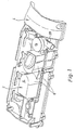
- FIG. 1 shows a perspective view of an oil separator 2 designated overall by the reference numeral 2 and to be described in detail below in the installed state on the outside of a cylinder head cover of an internal combustion engine designated overall by the reference numeral 4.
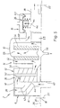
- FIGS. 3 and 4 show a perspective view of the oil separation device 2. Reference will now be made to FIG. 5, which is a partial schematic view of a sectional view of the oil separation device 2.
- the oil separation device 2 comprises a housing half shell 6, which accommodates all components of the oil separation device 2.
- the housing half-shell 6 is an integrally produced plastic injection-molded part, which comprises in the direction of the cylinder head cover 4 extended codessuitewandungen 8.
- the peripheral side walls 8 start from an upper cover wall 10, wherein a plurality of cup-shaped housing portions 12, 14, 16 are formed.
- the respective diagnosessuitewandungen 8 go into a frontal, circumferential edge 18, with which the housing half-shell 6 against an outer side 20 of the cylinder head cover 4 is sealingly applied.
- the housing half-shell 6 can then be screwed to the outside 20 of the cylinder head cover 4 via screws 22 indicated in FIG. 5 and shown in FIGS. 1 to 4.
- the peripheral end edge 18 forms or defines a contact plane 26.
- the housing region 12 forms a substantially pot-shaped chamber, in which a pre-separation device 28 and a cyclone separation device 30 is provided.
- a fine separator 32 is included in the adjoining cup-shaped housing portion 14, a fine separator 32 is included with a formed for example as a yarn package Feinabscheideieri 34.
- the opposite to the housing portions 12, 14 less tall housing portion 16 includes a valve device 36 which releases an outlet 38 of the oil separation device 2 to the intake of the internal combustion engine, not shown, or closes and thus the pressure of the crankcase gases after limited above.
- the cascaded separation steps are designed as follows:
- the pre-separation device 28 is arranged above an inlet opening 40 for crankcase gases in the cylinder head cover 4 and, as can be seen in FIG. 5, comprises flow guide walls 42 which effect a preferably multiple deflection of the crankcase gases flowing into the oil separation device 2.
- a reflux opening 44 is provided for liquid deposited in this stage. From the reflux opening 44 at the bottom end of a Strömungsleitwandung 42, the separated liquid then drips downwards against the flow of the crankcase gas and thus passes directly back into the engine compartment below the cylinder head cover 4.
- the flowing crankshaft gas into the cyclone separator 30 arranged cascaded below.
- This comprises a helical flow path 46.
- the helical flow path 46 is formed by a helix 48 having a central opening 50, through which a tubular or cylindrical inner piece 52 is inserted and connected substantially tightly to the helix 48.
- the peripheral edges 54 of the coil 48 are substantially sealing against the inside of the diligentssuitewandungen 8 of the housing half-shell 8.
- the helical passages of the helix 48 and the housing half shell 6, the helical flow path 46 is formed or limited by the inner piece 52. Due to inertial forces, the liquid components in the helically flowing crankcase gas are deposited radially outward and flow down the spiral path due to their gravity.
- the radial depth of the helical flow path 46 can be varied. This can preferably be done by using different coils 48 with different radial depth, which is preferably achieved by different sized inner pieces 52 of the helix 48 with the same outer diameter of the helix 48. In this way, by selecting and inserting different coils, a different flow cross-section for adaptation to different engines and applications with otherwise constant construction and dimensioning of the oil separation device 2 can be achieved.
- the fine separator 32 downstream of which is housed in the housing portion 14, comprises a cylindrical yarn package as a fine separator insert 34, which is closed on its cylinder head-facing side.
- the flowing crankcase gases pass through the cylindrical wall of the yarn package thereby depositing residual very fine liquid droplets which, due to gravity, pass downwardly within the yarn package towards the cylinder head cover.
- Figure 5 There is provided in Figure 5 only schematically indicated ⁇ lab 1500ö réelle 56 in the cylinder head cover.
- the yarn package comprises at its upper end an outlet opening 58. In this area, the top wall 10 is bulged slightly upwards.
- the Kurbeiwellengase flowing through the outlet opening 58 are then deflected immediately in the region of the bulge by 90 ° and then deflected again by 90 ° down in the direction of the cylinder head cover 4. Due to the formation of the bulged portion 10 as a separate component is the Manufacturability of the housing half shell 6 in terms of mold complexity significantly simplified. Due to the very steep design of the overflow channel 60, the tree space required in the longitudinal direction is kept as low as possible. In a recess between the housing portions 14 and 16 engages a mating contour 59, which is formed on the cylinder head cover, so that no dead volume is formed, in which liquid could accumulate. From the overflow channel 60, the flowing crankcase gas passes into the housing region 16, where the valve device 36 is provided.
- the valve device 36 comprises a diaphragm 62, shown diagrammatically in FIG. 5, which on the one hand communicates with the atmosphere and, on the other hand, is acted upon by the crankcase gas.
- a diaphragm 62 shown diagrammatically in FIG. 5, which on the one hand communicates with the atmosphere and, on the other hand, is acted upon by the crankcase gas.
- the valve means 36 closes an opening 64, under the pressure of the atmosphere.
- the port 64 is released and crankcase gases are supplied to (re) combustion.
- FIG. 6 schematically shows two different embodiments of coils 48 with different radial depths of the flow path, which are achieved with cylindrical inner pieces 52 of different diameters while the outside diameter of the coil 48 remains the same.
Landscapes
- Engineering & Computer Science (AREA)
- Mechanical Engineering (AREA)
- General Engineering & Computer Science (AREA)
- Lubrication Details And Ventilation Of Internal Combustion Engines (AREA)
- Cylinder Crankcases Of Internal Combustion Engines (AREA)
Claims (8)
- Dispositif de séparation d'huile (2) pour gaz de carter de vilebrequin d'un moteur à combustion interne, comprenant un préséparateur (28), un séparateur cyclone (30), un séparateur fin (32) et le cas échéant un système de soupape (36) qui sont montés en cascade sur un capot de culasse (4) du moteur à combustion interne,
caractérisé en ce que
dans la direction de l'écoulement ou de la cascade, en amont du séparateur cyclone (30), un orifice d'évacuation d'huile (44) prévu à l'intérieur du préséparateur (28) permet de recycler l'huile séparée dans le préséparateur (28), et le préséparateur (28), le séparateur cyclone (30), le séparateur fin (32) et éventuellement le système de soupape (36) sont disposés sur la face extérieure (20) du capot de culasse (4) et recouverts par une demi-coque de boîtier (6) qui, conjointement avec la face extérieure (20) du capot de culasse (4), forme un boîtier pour tous les composants du dispositif de séparation (2). - Dispositif de séparation d'huile selon la revendication 1,
caractérisé en ce que
l'orifice d'évacuation d'huile (44) est prévu dans une paroi de guidage d'écoulement (42) du préséparateur (28). - Dispositif de séparation d'huile selon la revendication 1 ou 2,
caractérisé en ce que
l'orifice d'évacuation d'huile (44) est adjacent à une paroi de boîtier qui sépare le préséparateur (28) et le séparateur cyclone (30). - Dispositif de séparation d'huile selon la revendication 1, 2 ou 3,
caractérisé en ce que
la surface de section transversale libre de l'orifice d'évacuation d'huile (44) se situe en projection à l'intérieur d'un orifice d'admission (40) pour les gaz de carter de vilebrequin dans le dispositif de séparation d'huile. - Dispositif de séparation d'huile selon la revendication 1,
caractérisé en ce que
la demi-coque (6) de boîtier est une pièce en matière plastique fabriquée d'un seul tenant, en particulier une pièce moulée par injection. - Dispositif de séparation d'huile selon l'une quelconque des revendications précédentes,
caractérisé en ce que
des parois de guidage d'écoulement (42) et/ou un insert hélicoïdal (48) pour le séparateur cyclone (30) et/ou un insert séparateur (34) pour le séparateur fin (32) et/ou le système de soupape (36) peuvent être installés de manière prémontée dans la demi-coque de boîtier (6). - Dispositif de séparation d'huile selon l'une quelconque des revendications précédentes,
caractérisé en ce que
la demi-coque de boîtier (6) est étanchée par un élément d'étanchéité circulaire par rapport à la face extérieure (20) du capot de culasse (4). - Dispositif de séparation d'huile selon l'une quelconque des revendications précédentes,
caractérisé en ce que
la demi-coque de boîtier (6) comprend des parois latérales périphériques (8) qui s'étendent en direction du capot de culasse (4) et se prolongent dans un bord périphérique (18) frontal par lequel la demi-coque de boîtier (6) est appliquée de façon étanche contre la face extérieure (20) du capot de culasse (4).
Applications Claiming Priority (3)
| Application Number | Priority Date | Filing Date | Title |
|---|---|---|---|
| DE10127817 | 2001-06-07 | ||
| DE10127817A DE10127817A1 (de) | 2001-06-07 | 2001-06-07 | Ölabscheidevorrichtung für Kurbelgehäusegase einer Verbrennungskraftmaschine |
| PCT/DE2002/000970 WO2002099257A1 (fr) | 2001-06-07 | 2002-03-16 | Dispositif de separation d'huile pour gaz de carter de vilebrequin de moteur a combustion interne |
Publications (2)
| Publication Number | Publication Date |
|---|---|
| EP1402156A1 EP1402156A1 (fr) | 2004-03-31 |
| EP1402156B1 true EP1402156B1 (fr) | 2007-01-03 |
Family
ID=7687609
Family Applications (1)
| Application Number | Title | Priority Date | Filing Date |
|---|---|---|---|
| EP02729799A Expired - Lifetime EP1402156B1 (fr) | 2001-06-07 | 2002-03-16 | Dispositif de separation d'huile pour gaz de carter de vilebrequin de moteur a combustion interne |
Country Status (5)
| Country | Link |
|---|---|
| US (1) | US6811586B2 (fr) |
| EP (1) | EP1402156B1 (fr) |
| JP (1) | JP4138644B2 (fr) |
| DE (2) | DE10127817A1 (fr) |
| WO (1) | WO2002099257A1 (fr) |
Families Citing this family (17)
| Publication number | Priority date | Publication date | Assignee | Title |
|---|---|---|---|---|
| DE20304016U1 (de) * | 2003-03-12 | 2004-07-22 | Hengst Gmbh & Co.Kg | Zylinderkopfhaube für eine Brennkraftmaschine |
| DE10313192C5 (de) * | 2003-03-25 | 2017-04-13 | Volkswagen Ag | Brennkraftmaschine und Verfahren zum Betreiben derselben |
| DE10321866A1 (de) * | 2003-05-15 | 2004-12-02 | Robert Bosch Gmbh | Vorrichtung zur Abscheidung von Flüssigkeit aus einem Gasstrom |
| US7059311B2 (en) * | 2004-08-12 | 2006-06-13 | Shiloh Industries, Inc. | Air/oil separating device |
| EP1695753B1 (fr) * | 2005-02-28 | 2014-06-04 | MANN+HUMMEL GmbH | Element filtrante avec un tube drainage |
| JP4506656B2 (ja) * | 2005-11-25 | 2010-07-21 | トヨタ紡織株式会社 | オイルミストセパレータ及びシリンダヘッドカバー |
| DE102005063274B9 (de) * | 2005-12-28 | 2013-05-08 | Elringklinger Ag | Ölabscheider |
| ATE553286T1 (de) * | 2005-12-29 | 2012-04-15 | Lg Chemical Ltd | Vorrichtung zur trennung von öl aus dem durchblasgas eines motors |
| US7594501B2 (en) * | 2006-12-22 | 2009-09-29 | Dichtungstechnik G. Bruss Gmbh & Co., Kg | Cylinder head cover for an internal combustion engine |
| KR101014532B1 (ko) * | 2008-07-25 | 2011-02-14 | 기아자동차주식회사 | 블로우바이 가스의 오일 분리장치 |
| JP2012057496A (ja) * | 2010-09-06 | 2012-03-22 | Nifco Inc | オイルセパレータ |
| US8887705B2 (en) | 2012-05-23 | 2014-11-18 | Honda Motor Co., Ltd. | Head cover baffle system for improving oil mist separation |
| US9101856B2 (en) | 2012-06-01 | 2015-08-11 | Bendix Commercial Vehicle Systems Llc | Purge exhaust processor |
| EP3009620A1 (fr) * | 2014-10-15 | 2016-04-20 | OFFICINE METALLURGICHE G. CORNAGLIA S.p.A. | Unité de séparation pour blow-by d'un moteur ic |
| US10132217B2 (en) | 2016-03-24 | 2018-11-20 | Caterpillar Inc. | Floating crankcase ventilation system and method |
| NO342497B1 (en) * | 2016-10-26 | 2018-06-04 | Viking Heat Engines As | Fluid separator for a displacement machine and a method for separating lubricant and working fluid in a displacement machine |
| IT201800010913A1 (it) | 2018-12-10 | 2020-06-10 | Fpt Ind Spa | Dispositivo e metodo di separazione di vapori di olio lubrificante di un motore a combustione interna |
Family Cites Families (10)
| Publication number | Priority date | Publication date | Assignee | Title |
|---|---|---|---|---|
| DE1164158B (de) | 1962-02-02 | 1964-02-27 | Maschf Augsburg Nuernberg Ag | OElabscheider zur Kurbelgehaeuseentlueftung |
| JPS5546703U (fr) * | 1978-09-20 | 1980-03-27 | ||
| DE3326881A1 (de) | 1983-07-26 | 1984-05-24 | Daimler-Benz Ag, 7000 Stuttgart | Kurbelgehaeuseentlueftung fuer eine brennkraftmaschine |
| DE19700733C2 (de) | 1997-01-11 | 2001-11-22 | Bayerische Motoren Werke Ag | Kurbelgehäuse-Entlüftung durch die Zylinderkopfhaube mit integrierten Zusatzfunktionen |
| DE29700579U1 (de) * | 1997-01-15 | 1997-03-13 | Mann & Hummel Filter | Anordnung zum Abscheiden von Flüssigkeitspartikeln aus einem Gasstrom |
| DE19715061C2 (de) * | 1997-04-11 | 1999-01-21 | Daimler Benz Ag | Entlüftungsvorrichtung für ein Kurbelgehäuse einer Brennkraftmaschine |
| JPH11264312A (ja) * | 1997-10-20 | 1999-09-28 | Nippon Soken Inc | 気液分離装置 |
| FR2789125B1 (fr) | 1999-01-29 | 2001-11-09 | Renault | Dispositif de reaspiration des gaz de carter d'un moteur |
| US6290738B1 (en) * | 1999-07-16 | 2001-09-18 | Nelson Industries, Inc. | Inertial gas-liquid separator having an inertial collector spaced from a nozzle structure |
| DE19951028A1 (de) * | 1999-10-22 | 2001-04-26 | Volkswagen Ag | Entlüftungsvorrichtung mit Ölabscheider für ein Kurbelgehäuse einer Brennkraftmaschine |
-
2001
- 2001-06-07 DE DE10127817A patent/DE10127817A1/de not_active Ceased
-
2002
- 2002-03-16 DE DE50209175T patent/DE50209175D1/de not_active Expired - Lifetime
- 2002-03-16 US US10/343,652 patent/US6811586B2/en not_active Expired - Fee Related
- 2002-03-16 JP JP2003502349A patent/JP4138644B2/ja not_active Expired - Fee Related
- 2002-03-16 WO PCT/DE2002/000970 patent/WO2002099257A1/fr active IP Right Grant
- 2002-03-16 EP EP02729799A patent/EP1402156B1/fr not_active Expired - Lifetime
Also Published As
| Publication number | Publication date |
|---|---|
| EP1402156A1 (fr) | 2004-03-31 |
| DE50209175D1 (de) | 2007-02-15 |
| US6811586B2 (en) | 2004-11-02 |
| DE10127817A1 (de) | 2002-12-12 |
| WO2002099257A1 (fr) | 2002-12-12 |
| JP4138644B2 (ja) | 2008-08-27 |
| JP2004521238A (ja) | 2004-07-15 |
| US20030110743A1 (en) | 2003-06-19 |
Similar Documents
| Publication | Publication Date | Title |
|---|---|---|
| EP1399649B1 (fr) | Dispositif separateur d'huile pour gas de carter de vilebrequin dans un moteur a combustion interne | |
| EP1402156B1 (fr) | Dispositif de separation d'huile pour gaz de carter de vilebrequin de moteur a combustion interne | |
| DE10127820A1 (de) | Ölabscheidevorrichtung für Kurbelgehäusegase einer Verbrennungskraftmaschine | |
| EP1751405B1 (fr) | Dispositif carter d'huile | |
| EP1568861B1 (fr) | Séparateur d'huile pour les gaz de carter d'un moteur à combustion | |
| EP1174597B1 (fr) | Ensemble pour un moteur à combustion avec un filtre à huile | |
| DE10338807B4 (de) | Entlüftungsvorrichtung für Brennkraftmaschinen | |
| DE202004004803U1 (de) | Ölabscheidevorrichtung für eine Brennkraftmaschine | |
| DE10235983A1 (de) | Luft-Öl-Abscheidevorrichtung für einen Motor | |
| DE102006012611A1 (de) | Zylinderkopf eines Verbrennungsmotors | |
| DE102006038700A1 (de) | Vorrichtung zur Abscheidung von Flüssigkeiten aus Gasen | |
| DE102004004753A1 (de) | Zylinderkopfhaube | |
| EP1360400A1 (fr) | Collecteur d'huile destine a un moteur a combustion interne | |
| DE102005006438A1 (de) | Einrichtung zur Entlüftung eines Kurbelgehäuses einer Brennkraftmaschine sowie Brennkraftmaschine mit insbesondere V-förmiger Anordnung der Zylinder | |
| DE202007003292U1 (de) | Ölabscheider mit mindestens einem Zyklon | |
| EP1676017B1 (fr) | Dispositif de degasage du carter de vilebrequin d'un moteur a combustion interne | |
| EP1310637A2 (fr) | Moteur avec au moins deux bancs de cylindres | |
| DE60123350T2 (de) | Zylinderkopfdeckel für eine Brennmaschine | |
| DE19644526C2 (de) | Entlüftungsvorrichtung für ein Kurbelgehäuse einer Brennkraftmaschine | |
| DE19632931C2 (de) | Entlüftungsvorrichtung für ein Kurbelgehäuse einer Brennkraftmaschine | |
| DE102004041110B4 (de) | Brennkraftmaschine und zugehörige Zylinderkopfhaube | |
| EP1961928B1 (fr) | Préséparateur d'huile pour gaz de carter de vilebrequin | |
| DE19951103C2 (de) | Vorrichtung zum Einfüllen und Absaugen von Öl | |
| DE202007003094U1 (de) | Ölvorabscheider für Kurbelgehäusegas | |
| EP3250797A1 (fr) | Moteur a combustion interne pourvu retour d'huile comprenant un conduit d'huile |
Legal Events
| Date | Code | Title | Description |
|---|---|---|---|
| PUAI | Public reference made under article 153(3) epc to a published international application that has entered the european phase |
Free format text: ORIGINAL CODE: 0009012 |
|
| 17P | Request for examination filed |
Effective date: 20040107 |
|
| AK | Designated contracting states |
Kind code of ref document: A1 Designated state(s): AT BE CH CY DE DK ES FI FR GB GR IE IT LI LU MC NL PT SE TR |
|
| GRAP | Despatch of communication of intention to grant a patent |
Free format text: ORIGINAL CODE: EPIDOSNIGR1 |
|
| GRAS | Grant fee paid |
Free format text: ORIGINAL CODE: EPIDOSNIGR3 |
|
| GRAA | (expected) grant |
Free format text: ORIGINAL CODE: 0009210 |
|
| AK | Designated contracting states |
Kind code of ref document: B1 Designated state(s): DE ES FR GB IT |
|
| REG | Reference to a national code |
Ref country code: GB Ref legal event code: FG4D Free format text: NOT ENGLISH |
|
| REF | Corresponds to: |
Ref document number: 50209175 Country of ref document: DE Date of ref document: 20070215 Kind code of ref document: P |
|
| PG25 | Lapsed in a contracting state [announced via postgrant information from national office to epo] |
Ref country code: ES Free format text: LAPSE BECAUSE OF FAILURE TO SUBMIT A TRANSLATION OF THE DESCRIPTION OR TO PAY THE FEE WITHIN THE PRESCRIBED TIME-LIMIT Effective date: 20070414 |
|
| ET | Fr: translation filed | ||
| GBV | Gb: ep patent (uk) treated as always having been void in accordance with gb section 77(7)/1977 [no translation filed] |
Effective date: 20070103 |
|
| PLBE | No opposition filed within time limit |
Free format text: ORIGINAL CODE: 0009261 |
|
| STAA | Information on the status of an ep patent application or granted ep patent |
Free format text: STATUS: NO OPPOSITION FILED WITHIN TIME LIMIT |
|
| PG25 | Lapsed in a contracting state [announced via postgrant information from national office to epo] |
Ref country code: GB Free format text: LAPSE BECAUSE OF FAILURE TO SUBMIT A TRANSLATION OF THE DESCRIPTION OR TO PAY THE FEE WITHIN THE PRESCRIBED TIME-LIMIT Effective date: 20070103 |
|
| 26N | No opposition filed |
Effective date: 20071005 |
|
| PG25 | Lapsed in a contracting state [announced via postgrant information from national office to epo] |
Ref country code: IT Free format text: LAPSE BECAUSE OF FAILURE TO SUBMIT A TRANSLATION OF THE DESCRIPTION OR TO PAY THE FEE WITHIN THE PRESCRIBED TIME-LIMIT Effective date: 20070103 |
|
| PGFP | Annual fee paid to national office [announced via postgrant information from national office to epo] |
Ref country code: FR Payment date: 20110401 Year of fee payment: 10 |
|
| REG | Reference to a national code |
Ref country code: FR Ref legal event code: ST Effective date: 20121130 |
|
| PG25 | Lapsed in a contracting state [announced via postgrant information from national office to epo] |
Ref country code: FR Free format text: LAPSE BECAUSE OF NON-PAYMENT OF DUE FEES Effective date: 20120402 |
|
| PGFP | Annual fee paid to national office [announced via postgrant information from national office to epo] |
Ref country code: DE Payment date: 20170529 Year of fee payment: 16 |
|
| REG | Reference to a national code |
Ref country code: DE Ref legal event code: R119 Ref document number: 50209175 Country of ref document: DE |
|
| PG25 | Lapsed in a contracting state [announced via postgrant information from national office to epo] |
Ref country code: DE Free format text: LAPSE BECAUSE OF NON-PAYMENT OF DUE FEES Effective date: 20181002 |