EP1398589A2 - Kühlmittelkühler - Google Patents
Kühlmittelkühler Download PDFInfo
- Publication number
- EP1398589A2 EP1398589A2 EP03016862A EP03016862A EP1398589A2 EP 1398589 A2 EP1398589 A2 EP 1398589A2 EP 03016862 A EP03016862 A EP 03016862A EP 03016862 A EP03016862 A EP 03016862A EP 1398589 A2 EP1398589 A2 EP 1398589A2
- Authority
- EP
- European Patent Office
- Prior art keywords
- mff
- coolant
- cooling
- cooler
- flat tubes
- Prior art date
- Legal status (The legal status is an assumption and is not a legal conclusion. Google has not performed a legal analysis and makes no representation as to the accuracy of the status listed.)
- Granted
Links
- 239000002826 coolant Substances 0.000 title claims abstract description 48
- 238000001816 cooling Methods 0.000 claims abstract description 68
- 238000005476 soldering Methods 0.000 claims description 4
- 238000005192 partition Methods 0.000 claims description 2
- 239000011324 bead Substances 0.000 description 4
- 238000000034 method Methods 0.000 description 4
- 229910052782 aluminium Inorganic materials 0.000 description 2
- 238000004519 manufacturing process Methods 0.000 description 2
- 229910052751 metal Inorganic materials 0.000 description 2
- 239000002184 metal Substances 0.000 description 2
- XAGFODPZIPBFFR-UHFFFAOYSA-N aluminium Chemical compound [Al] XAGFODPZIPBFFR-UHFFFAOYSA-N 0.000 description 1
- 238000002485 combustion reaction Methods 0.000 description 1
- 239000000110 cooling liquid Substances 0.000 description 1
- 238000000265 homogenisation Methods 0.000 description 1
- 230000000717 retained effect Effects 0.000 description 1
- 238000009423 ventilation Methods 0.000 description 1
Images



Classifications
-
- F—MECHANICAL ENGINEERING; LIGHTING; HEATING; WEAPONS; BLASTING
- F28—HEAT EXCHANGE IN GENERAL
- F28F—DETAILS OF HEAT-EXCHANGE AND HEAT-TRANSFER APPARATUS, OF GENERAL APPLICATION
- F28F3/00—Plate-like or laminated elements; Assemblies of plate-like or laminated elements
- F28F3/02—Elements or assemblies thereof with means for increasing heat-transfer area, e.g. with fins, with recesses, with corrugations
- F28F3/04—Elements or assemblies thereof with means for increasing heat-transfer area, e.g. with fins, with recesses, with corrugations the means being integral with the element
- F28F3/042—Elements or assemblies thereof with means for increasing heat-transfer area, e.g. with fins, with recesses, with corrugations the means being integral with the element in the form of local deformations of the element
- F28F3/044—Elements or assemblies thereof with means for increasing heat-transfer area, e.g. with fins, with recesses, with corrugations the means being integral with the element in the form of local deformations of the element the deformations being pontual, e.g. dimples
-
- F—MECHANICAL ENGINEERING; LIGHTING; HEATING; WEAPONS; BLASTING
- F28—HEAT EXCHANGE IN GENERAL
- F28D—HEAT-EXCHANGE APPARATUS, NOT PROVIDED FOR IN ANOTHER SUBCLASS, IN WHICH THE HEAT-EXCHANGE MEDIA DO NOT COME INTO DIRECT CONTACT
- F28D1/00—Heat-exchange apparatus having stationary conduit assemblies for one heat-exchange medium only, the media being in contact with different sides of the conduit wall, in which the other heat-exchange medium is a large body of fluid, e.g. domestic or motor car radiators
- F28D1/02—Heat-exchange apparatus having stationary conduit assemblies for one heat-exchange medium only, the media being in contact with different sides of the conduit wall, in which the other heat-exchange medium is a large body of fluid, e.g. domestic or motor car radiators with heat-exchange conduits immersed in the body of fluid
- F28D1/04—Heat-exchange apparatus having stationary conduit assemblies for one heat-exchange medium only, the media being in contact with different sides of the conduit wall, in which the other heat-exchange medium is a large body of fluid, e.g. domestic or motor car radiators with heat-exchange conduits immersed in the body of fluid with tubular conduits
- F28D1/053—Heat-exchange apparatus having stationary conduit assemblies for one heat-exchange medium only, the media being in contact with different sides of the conduit wall, in which the other heat-exchange medium is a large body of fluid, e.g. domestic or motor car radiators with heat-exchange conduits immersed in the body of fluid with tubular conduits the conduits being straight
- F28D1/0535—Heat-exchange apparatus having stationary conduit assemblies for one heat-exchange medium only, the media being in contact with different sides of the conduit wall, in which the other heat-exchange medium is a large body of fluid, e.g. domestic or motor car radiators with heat-exchange conduits immersed in the body of fluid with tubular conduits the conduits being straight the conduits having a non-circular cross-section
- F28D1/05366—Assemblies of conduits connected to common headers, e.g. core type radiators
-
- F—MECHANICAL ENGINEERING; LIGHTING; HEATING; WEAPONS; BLASTING
- F28—HEAT EXCHANGE IN GENERAL
- F28F—DETAILS OF HEAT-EXCHANGE AND HEAT-TRANSFER APPARATUS, OF GENERAL APPLICATION
- F28F3/00—Plate-like or laminated elements; Assemblies of plate-like or laminated elements
- F28F3/02—Elements or assemblies thereof with means for increasing heat-transfer area, e.g. with fins, with recesses, with corrugations
- F28F3/025—Elements or assemblies thereof with means for increasing heat-transfer area, e.g. with fins, with recesses, with corrugations the means being corrugated, plate-like elements
-
- F—MECHANICAL ENGINEERING; LIGHTING; HEATING; WEAPONS; BLASTING
- F28—HEAT EXCHANGE IN GENERAL
- F28F—DETAILS OF HEAT-EXCHANGE AND HEAT-TRANSFER APPARATUS, OF GENERAL APPLICATION
- F28F9/00—Casings; Header boxes; Auxiliary supports for elements; Auxiliary members within casings
- F28F9/001—Casings in the form of plate-like arrangements; Frames enclosing a heat exchange core
Definitions
- the invention relates to a coolant cooler for motor vehicles according to the preamble of Claim 1 or Claim 9.
- the coolant cooler is, for example, from EP 693 617 B1 or DE 43 28 448 C2 known.
- the known coolant coolers are so-called Cross flow coolers, as they are very often found in cars.
- the cooler points probably a soldered cooling network.
- Such cooling networks usually have both opposite sides, on which no collection boxes are arranged, i.e. parallel to the longitudinal axis of the flat tubes, a so-called inner side part that at Aluminum sheet made cooling network also a - possibly deformed - Aluminum sheet is.
- the inner side panels are the most lateral
- the cooling fin is soldered and also connected to the header boxes.
- Have coolant coolers often also outer side parts, for example to reinforce the coolant cooler and are provided for fastening it in the motor vehicle.
- the inner side panels provide the cooling network with the required strength. They affect manufacturing costs and of course also go into the weight of the coolant cooler.
- Both Known coolant coolers are provided, which consist of at least one lower or upper separate pipe of the row of pipes of the cooling network, which as Vent pipe or are designed as a suction pipe. The pipes in the row of pipes are off For reasons of economy, all trained in the same way. The separated pipes are at least not fully available for operational heat exchange.
- the DE 43 28 448 has a connecting line located at the bottom as a cooler component is a part (several flat tubes) of the cooling network. This is the connecting line Filling the circuit accomplished.
- a check valve is required to the to separate the discharge-side collection box from the suction-side collection box so that during flow of all flat tubes as uniform as possible during operation.
- the object of the invention is to provide a coolant cooler with a stable cooling network that can be changed without having to be changed for coolers with or without integrated filling function can be used for the cooling circuit.
- independent claim 9 lead to an inventive Coolant cooler, which also has a more uniform temperature distribution over the entire cooling network, which increased its performance. The Lateral areas of the coolant cooler are warmed up more quickly.
- the cooler component is a multifunction flat tube (MFF) with a greater moment of resistance than that of the other flat tubes, the ends are fluidly connected to the two collection boxes, so that it is on Cooling process is involved, which fulfills the function of an inner side part of the cooling network and which can optionally be used as a filling line for filling the cooling circuit.
- MFF multifunction flat tube
- the cooling network designed according to the invention is at least as stable as a cooling network with conventional inner side parts, because the MFF has a correspondingly high Moment of resistance.
- the cooling network preferably has an MFF on both sides. she are soldered to the outer cooling fin. They are also in with the flat tubes of the Cooling network connected identically to the collection boxes, or with the Collecting tubes associated tube sheets, so that the coolant through the Multifunction flat tubes can flow. They are also preferably of the same length (Cooling net height) and width (cooling net depth) like the other flat tubes. However, it can Cooling network also consist of several rows of flat tubes. In this case too Width of the MFF over the entire depth of the cooling network, but the width of the MFF is according to the number of rows of tubes is a multiple of the width of the flat tubes, which also still contains the distance between the rows of pipes.
- the coolant cooler according to claims 2 and 10 is preferably a downflow cooler with inlet collector box at the top and outlet collector box at the bottom trained and intended for heavy motor vehicles to the coolant Cool internal combustion engine.
- the exterior previously required in heavy motor vehicles There is no need for a filling line for the cooling system.
- the claim 4 describes possible training of the MFF.
- the one for each For example, the MFF training selected depends on whether the Filling function is provided there or not.
- the specialist selects a suitable interior insert for the MFF and / or the MFF by forming such that the amount of cooling liquid to be filled in can be introduced into the cooling circuit within a reasonable period of time.
- the Expert an optimum between the period mentioned and the longest possible Aim for the heat exchange rate of the MFF, because the MFF is constantly used by the coolant during operation flows through and is therefore involved in heat exchange.
- the MFF formed inside from the point of view of efficient heat exchange, whereby but it was found that the MFF had a very positive influence on the Uniformization of the temperature distribution can be exercised over the entire cooler can by having a greater throughput of coolant through the MFF than through a single flat tube can flow.
- the flow resistance and / or the The cross-sectional size of the MFF is different from that - or that of a single one Flat tube. (Claim 9) In particular, the cross-sectional size of the MFF is larger than that of a single flat tube.
- the temperature distribution is usually parabolic Course across the width of the cooler, with the maximum approximately in the middle of the cooling network lies.
- the outside flat tubes are usually poorly flowed through and hardly at Heat exchange involved.
- the flat tubes of the coolant cooler are very flat tubes with a height (small diameter) of only about 1.8 mm, which has no inner inserts have.
- the MFF is a flat tube in which the height (small diameter) for example 10 mm - at least a multiple of the other flat tubes - is.
- the coolant cooler is intended for use in heavy motor vehicles. It is a so-called downdraft cooler in which the inlet header box 1 is arranged at the top and the outlet header box 2 at the bottom.
- the inlet header box 1 has an inlet connector 15 and the outlet header box 2 has a corresponding outlet connector 16 , with which the cooler is integrated in a cooling circuit, not shown, together with an expansion tank, also not shown, and with other associated elements. Corresponding flow arrows are shown.
- the coolant cooler has a soldered cooling network which, in a known manner, consists of alternately arranged flat tubes 3 and cooling fins 4 .
- the preferred embodiment has been shown in the exemplary embodiments shown, according to which a multifunction flat tube MFF is arranged on each side of the cooling network.
- the MFF is soldered to the most laterally arranged cooling fin 4 in order to achieve good heat transfer.
- the MFF takes over the function of the usual inner side parts, ie such side parts can be omitted.
- the tubular shape of the MFF has a higher section modulus Wx , Wy , (Fig. 7) compared to the flat inner side parts that have been customary so far, so that in comparison it can be made from thinner sheet metal without increasing the weight of the cooling network or the stability to reduce the cooling network.
- the section modulus Wx, Wy of the MFF is significantly greater than the section modulus of an individual flat tube 3 , since it is made from thicker sheet metal b and has a much greater height (“small diameter” d ) than the flat tubes 3 .
- Figures 1 and 2 show the narrow sides of the flat tubes 3 and the narrow sides of the MFF .
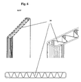
- the MFF has the same cooling network depth t ("large diameter") and the same cooling network height h (length) as the other flat tubes 3 . It is connected in terms of flow in the same way as the flat tubes 3 with header boxes 1 and 2 , which can be seen from FIG. 4 to be described later, and it is therefore involved in the cooling process.
- the MFF have a filling function. Therefore, a filling opening 12 is provided on the inlet header box 1 and a filling line 10 , which is fastened to the wall 9 of the inlet header box 1 . It can be seen from FIG. 3 that the filling line 10 has an incline in order to ensure that the line routing rises upwards.
- the space enclosed by the inlet header box 1 is divided into three chambers 17 , 18 and 19 . This division is achieved by the arrangement of two partitions 13 , which essentially separate the chambers 17 and 19 , in each of which the end 5 of the MFF flows, from the middle chamber 18 in terms of flow technology.
- the filling line 10 leads from the filling opening 12 to the two chambers 17 and 19 .
- the MFF has a "small diameter" d (height) of just over 10 mm and could be designed according to FIG. 7.
- the wide walls 7 of the MFF have inward projections 8 which are soldered together.
- such a design should be chosen that the internal flow resistance of the MFF ensures that the circuit is filled within a reasonable period of time.
- the filling usually takes place via the expansion tank, not shown, from which a line, also not shown, goes to the filling opening 12 . With a compact design, the expansion tank can be located directly on the inlet header box 1 .
- FIG. 3 With regard to FIG. 3, it is still to be explained that only one half of the cooler is shown there, in which the filling opening 12 is arranged approximately in the middle thereof.
- a portion of the coolant constantly flows from the expansion tank via the filling line 10 into the chambers 17 and 19 and through the MFF , so that they can contribute to cooling the coolant, the heat being dissipated via the cooling fins 4 through which cooling air flows ,
- the filling function of the MFF has been dispensed with.
- the other advantageous functions are retained here, namely in particular those which are used to even out the temperature distribution over the entire cooler and to provide a stable cooling network.
- the replacement of the inner side part of the cooling network by the MFF is also preferred here, but does not necessarily have to be realized.
- the arrows drawn in the inlet header box 1 indicate that a larger volume flow flows through the MFF than through each individual flat tube 3 . It must the inner flow resistance in both MFF not necessarily be the same size so that the flow rates in both MFF can have different size. This not only improves performance, it also reduces the temperature differences that sometimes lead to stress cracks.
- the MFF has a suitable inner insert 26 . (Fig. 5, 6) Of course, the inner insert 26 is soldered into the MFF for reasons of stability and because of the better heat transfer.
- the MFF advantageously has a bead 20 or similar deformation at its ends 5 .
- This bead 20 serves as a stop for the MFF during assembly of the cooling network, ie the flat tubes 3 and the cooling fins 4 with the tube sheets 21, which are joined together before the soldering process is carried out.
- 4 shows that openings 22 are provided in the tube sheets 21 in a manner known per se, which are provided with a collar 23 in order to achieve a quality-appropriate soldering of the tube ends inserted into the openings 22 .
- the collars 23 are directed towards the cooling network.
- the tube sheets 21 have a circumferential channel 24 with a seal 25 arranged therein in order to be able to mechanically and firmly connect the edge of the collecting boxes 1 , 2 made of plastic. (Fig. 4)
- FIG. 5 and 7 show a welded MFF
- FIG. 6 shows a soldered MFF in several views or sections, the images speak for themselves.
- the design of the MFF with separate parallel chambers was not shown in the drawing.
- Such training can be found in the prior art.
- the wide walls 7 have inward longitudinal beads which touch and which are soldered to one another.
- the longitudinal beads are similar to the projections 8 , with the difference that they run over the entire length of the tube.
Landscapes
- Engineering & Computer Science (AREA)
- Physics & Mathematics (AREA)
- Thermal Sciences (AREA)
- Mechanical Engineering (AREA)
- General Engineering & Computer Science (AREA)
- Heat-Exchange Devices With Radiators And Conduit Assemblies (AREA)
- Cooling Or The Like Of Electrical Apparatus (AREA)
- Cooling Or The Like Of Semiconductors Or Solid State Devices (AREA)
- Superconductors And Manufacturing Methods Therefor (AREA)
Abstract
Description
- Fig. 1
- Prinzip - Seitenansicht auf den Kühlmittelkühler mit Befüllfunktion der MFF;
- Fig. 2
- wie Fig. 1 aber ohne Befüllfunktion;
- Fig. 3
- Teil - Längsschnitt durch einen Kühler mit Befüllfunktion;
- Fig. 4
- Ausschnitt aus einem Längsschnitt (ohne Befüllfunktion);
- Fig. 5, 6 und 7
- Bauformen des MFF;
Claims (10)
- Kühlmittelkühler für ein Kraftfahrzeug, der in dessen Kühlkreislauf eingebunden ist, mit einem Eintrittssammelkasten (1) mit oder ohne Befüllöffnung (12), einem Austrittssammelkasten (2), einem gelöteten Kühlnetz, bestehend aus Flachrohren (3) und Kühlrippen (4) mit einer bestimmten Kühlnetzhöhe (h) und Kühlnetztiefe (t), wobei die Flachrohre (3) die beiden Sammelkästen (1, 2) verbinden und mit ein - oder beidseitig des Kühlnetzes angeordnetem Kühlerbauteil, das mit der angrenzenden Kühlrippe (4) und mit den Sammelkästen (1, 2) mittels Löten verbunden ist,
dadurch gekennzeichnet, dass das Kühlerbauteil ein Multifunktionsflachrohr (MFF) ist, das ein größeres Widerstandsmoment (Wx, Wy) aufweist als dasjenige eines einzelnen Flachrohres (3), dass die Enden (5) des (MFF) mit den beiden Sammelkästen (1, 2) verbunden sind, so dass es vom Kühlmittel durchströmt ist und das ferner die Funktion eines inneren Seitenteils des Kühlnetzes erfüllt und wahlweise als Befüllleitung zur Befüllung des Kühlkreislaufs nutzbar ist. - Kühlmittelkühler nach Anspruch 1, dadurch gekennzeichnet, dass der Kühlmittelkühler ein Fallstromkühler mit oben liegendem Eintrittssammelkasten (1) und unten liegendem Austrittssammelkasten (2) ist, der für schwere Kraftfahrzeuge vorgesehen ist, wobei den Sammelkästen (1, 2) Rohrböden (21) zugeordnet sind, die in bekannter Weise Öffnungen (22) zur Aufnahme der Enden der Flachrohre (3) aufweisen und die wenigstens eine Öffnung zur Aufnahme eines Endes (5) des (MFF) besitzen.
- Kühlmittelkühler nach Anspruch 1 oder 2, dadurch gekennzeichnet, dass das (MFF) vorzugsweise die gleiche Kühlnetzhöhe (h) und Kühlnetztiefe (t) wie die übrigen Flachrohre (3) aufweist und vorzugsweise in mit den übrigen Flachrohren (3) identischer Ausführung mit den Sammelkästen (1, 2) verlötet ist.
- Kühlmittelkühler nach einem der Ansprüche 1 bis 3, dadurch gekennzeichnet, dass das (MFF) ein gelötetes oder geschweißtes Rohr ist, das entweder einen geeigneten Inneneinsatz (6) besitzt oder dessen Breitwände (7) durch entsprechende Verformung in mehrere getrennte Kammern aufgeteilt ist oder dessen Breitwände (7) nach innen gerichtete Vorsprünge (8) besitzen, die miteinander verbunden sind.
- Kühlmittelkühler nach einem der vorstehenden Ansprüche, dadurch gekennzeichnet, dass der innere Strömungswiderstand des (MFF) kleiner ist als in den übrigen Flachrohren (3).
- Kühlmittelkühler nach einem der vorstehenden Ansprüche, dadurch gekennzeichnet, dass das (MFF) eine wesentlich größere Blechdicke und einen wesentlich größere Höhe (d) (kleiner Durchmesser) aufweist als die Flachrohre (3).
- Kühlmittelkühler nach einem der vorstehenden Ansprüche, bei dem das (MFF) eine Befüllfunktion besitzt, dadurch gekennzeichnet, dass an der Wand (9) des Eintrittssammelkastens (1) eine Befüllleitung (10) von der Befüllöffnung (12) bis zum (MFF) reichend angeordnet ist und dass im Eintrittssammelkasten (1) eine Trennwand (13) zwischen dem (MFF) und dem angrenzenden Flachrohr (3) vorhanden ist, um das (MFF) vom zirkulierenden Kühlmittel zu trennen.
- Kühlmittelkühler nach Anspruch 1 und 7 dadurch gekennzeichnet, dass die Befüllleitung (10) in Richtung zum (MFF) hin eine Neigung aufweist, um der Forderung nach von unten nach oben ansteigender Leitungsverlegung zu entsprechen.
- Kühlmittelkühler für ein Kraftfahrzeug, der in dessen Kühlkreislauf eingebunden ist, mit einem Eintrittssammelkasten (1) mit oder ohne Befüllöffnung (12), einem Austrittssammelkasten (2), einem gelöteten Kühlnetz, bestehend aus Flachrohren (3) und Kühlrippen (4) mit einer bestimmten Kühlnetzhöhe (h) und Kühlnetztiefe (t), wobei die Flachrohre (3) die beiden Sammelkästen (1, 2) verbinden und mit ein - oder beidseitig des Kühlnetzes angeordnetem Kühlerbauteil, das mit der angrenzenden Kühlrippe (4) und mit den Sammelkästen (1, 2) mittels Löten verbunden ist,
dadurch gekennzeichnet, dass das Kühlerbauteil ein Multifunktionsflachrohr (MFF) ist, dessen Enden (5) mit den beiden Sammelkästen (1, 2) verbunden sind, so dass es vom Kühlmittel durchströmt ist, wobei das (MFF) so ausgebildet ist, dass eine bestimmte anteilige Menge pro Zeiteinheit des Kühlmittels durch das (MFF) leitbar ist, die größer ist als die Menge pro Zeiteinheit, die durch ein einzelnes Flachrohr (3) strömt, wodurch die Temperaturverteilung über den gesamten Kühler beeinflussbar ist. - Kühlmittelkühler nach Anspruch 9, dadurch gekennzeichnet, dass der Kühlmittelkühler ein Fallstromkühler mit oben liegendem Eintrittssammelkasten (1) und unten liegendem Austrittssammelkasten (2) ist, der für schwere Kraftfahrzeuge vorgesehen ist, wobei den Sammelkästen (1, 2) Rohrböden (21) zugeordnet sind, die in bekannter Weise Öffnungen (22) zur Aufnahme der Enden der Flachrohre (3) aufweisen und die wenigstens eine Öffnung zur Aufnahme eines Endes (5) des (MFF) besitzen.
Applications Claiming Priority (2)
| Application Number | Priority Date | Filing Date | Title |
|---|---|---|---|
| DE10242311 | 2002-09-12 | ||
| DE10242311A DE10242311A1 (de) | 2002-09-12 | 2002-09-12 | Kühlmittelkühler |
Publications (3)
| Publication Number | Publication Date |
|---|---|
| EP1398589A2 true EP1398589A2 (de) | 2004-03-17 |
| EP1398589A3 EP1398589A3 (de) | 2005-10-05 |
| EP1398589B1 EP1398589B1 (de) | 2007-04-18 |
Family
ID=31724688
Family Applications (1)
| Application Number | Title | Priority Date | Filing Date |
|---|---|---|---|
| EP03016862A Expired - Lifetime EP1398589B1 (de) | 2002-09-12 | 2003-07-24 | Kühlmittelkühler |
Country Status (4)
| Country | Link |
|---|---|
| US (1) | US6904965B2 (de) |
| EP (1) | EP1398589B1 (de) |
| AT (1) | ATE360182T1 (de) |
| DE (2) | DE10242311A1 (de) |
Cited By (1)
| Publication number | Priority date | Publication date | Assignee | Title |
|---|---|---|---|---|
| EP1764571A1 (de) * | 2005-09-17 | 2007-03-21 | Behr GmbH & Co. KG | Wärmeübertrager, insbesondere Heizkörper, für eine Klimaanlage |
Families Citing this family (23)
| Publication number | Priority date | Publication date | Assignee | Title |
|---|---|---|---|---|
| JP3701927B2 (ja) * | 2002-06-18 | 2005-10-05 | 株式会社ケーヒン | 車両用空調装置 |
| DE102004057526B4 (de) * | 2003-12-03 | 2020-08-20 | Denso Corporation | Stapelkühler |
| DE10359806A1 (de) | 2003-12-19 | 2005-07-14 | Modine Manufacturing Co., Racine | Wärmeübertrager mit flachen Rohren und flaches Wärmeübertragerrohr |
| US7159648B2 (en) * | 2004-04-23 | 2007-01-09 | Modine Manufacturing Company | Weather protected heat exchanger |
| DE102004019769A1 (de) | 2004-04-23 | 2005-11-17 | Bayerische Motoren Werke Ag | Wärmetauscher für ein Kraftfahrzeug sowie Verfahren zu dessen Herstellung |
| FR2871739B1 (fr) * | 2004-06-21 | 2006-09-15 | Valeo Climatisation Sa | Boitier a couvercle d'etancheite externe et de calage, pour une installation de chauffage, ventilation et/ou climatisation d'habitacle |
| DE102005010493A1 (de) * | 2005-03-08 | 2006-09-14 | Modine Manufacturing Co., Racine | Wärmeübertrager mit flachen Rohren und flaches Wärmeübertragerrohr |
| US20060266506A1 (en) * | 2005-05-27 | 2006-11-30 | Lg Electronics Inc. | Heat exchanger for dryer and condensing type dryer using the same |
| DE102005042315A1 (de) * | 2005-09-06 | 2007-03-08 | Behr Gmbh & Co. Kg | Kühlmittelkühler, insbesondere für ein Kraftfahrzeug |
| DE102005053924B4 (de) | 2005-11-11 | 2016-03-31 | Modine Manufacturing Co. | Ladeluftkühler in Plattenbauweise |
| DE102006018217A1 (de) * | 2006-04-19 | 2007-10-25 | Modine Manufacturing Co., Racine | Wärmetauscher für Kraftfahrzeuge |
| US8424592B2 (en) | 2007-01-23 | 2013-04-23 | Modine Manufacturing Company | Heat exchanger having convoluted fin end and method of assembling the same |
| US20090250201A1 (en) | 2008-04-02 | 2009-10-08 | Grippe Frank M | Heat exchanger having a contoured insert and method of assembling the same |
| CN101589286B (zh) * | 2007-01-23 | 2011-09-28 | 摩丁制造公司 | 热交换器和方法 |
| US9658005B2 (en) * | 2010-11-18 | 2017-05-23 | Hamilton Sundstrand Corporation | Heat exchanger system |
| DE102013221447A1 (de) | 2013-10-22 | 2015-05-07 | Volkswagen Aktiengesellschaft | Kühlsystem für ein Kraftfahrzeug |
| SE1450473A1 (sv) * | 2014-04-22 | 2015-10-23 | Titanx Engine Cooling Holding Ab | Värmeväxlare innefattande en kärna av rör |
| DE102014010632A1 (de) | 2014-07-17 | 2016-01-21 | Modine Manufacturing Company | Gelöteter Wärmetauscher und Herstellungsverfahren |
| US10309730B2 (en) * | 2015-06-16 | 2019-06-04 | Hamilton Sundstrand Corporation | Mini-channel heat exchanger tube sleeve |
| ES2930282T3 (es) * | 2016-05-03 | 2022-12-09 | Carrier Corp | Disposición de intercambiadores de calor |
| CN107941065A (zh) * | 2017-11-13 | 2018-04-20 | 山东同创汽车散热装置股份有限公司 | 缩口换热管 |
| DE102019121494A1 (de) * | 2019-08-09 | 2021-02-11 | Mann+Hummel Gmbh | Wärmetauscheranordnung, Verfahren zur Herstellung einer Wärmetauscheranordnung und Brennkraftmaschine mit Wärmetauscheranordnung |
| US12298091B2 (en) | 2022-10-06 | 2025-05-13 | Hamilton Sundstrand Corporation | Heat exchanger with header embedded cooling channels |
Citations (3)
| Publication number | Priority date | Publication date | Assignee | Title |
|---|---|---|---|---|
| DE3512891A1 (de) | 1985-04-11 | 1986-10-16 | Süddeutsche Kühlerfabrik Julius Fr. Behr GmbH & Co KG, 7000 Stuttgart | Ladeluftkuehler fuer verbrennungskraftmaschinen |
| DE4328448C2 (de) | 1993-08-24 | 1995-08-17 | Behr Gmbh & Co | Wärmetauscher |
| EP0693617B1 (de) | 1994-07-19 | 1998-09-02 | Valeo GmbH | Querstromkühler mit Entlüftung |
Family Cites Families (15)
| Publication number | Priority date | Publication date | Assignee | Title |
|---|---|---|---|---|
| US3034770A (en) * | 1959-09-16 | 1962-05-15 | Continental Aviat & Eng Corp | Heat exchanger |
| US4098328A (en) * | 1977-06-16 | 1978-07-04 | Borg-Warner Corporation | Cross-flow radiator deaeration system |
| DE3616307A1 (de) * | 1986-05-14 | 1987-11-19 | Man Nutzfahrzeuge Gmbh | Kuehler, insbesondere fuer brennkraftmaschinen |
| DE3642911A1 (de) * | 1986-12-16 | 1988-07-07 | Daimler Benz Ag | Waermetraegerseitig geregelter querstromwaermetauscher mit zwei heizflaechen |
| US5101890A (en) * | 1989-04-24 | 1992-04-07 | Sanden Corporation | Heat exchanger |
| JP2968063B2 (ja) * | 1991-02-20 | 1999-10-25 | サンデン株式会社 | 熱交換器 |
| DE4232366A1 (de) * | 1991-07-11 | 1994-03-31 | Laengerer & Reich Gmbh & Co | Ölkühler |
| US5186248A (en) * | 1992-03-23 | 1993-02-16 | General Motors Corporation | Extruded tank condenser with integral manifold |
| GB2268260A (en) * | 1992-06-24 | 1994-01-05 | Llanelli Radiators Ltd | Heat exchange tubes formed from a unitary portion of sheet or strip material |
| DE4313567C1 (de) * | 1993-04-26 | 1994-09-01 | Daimler Benz Ag | Wärmetauscher für die unabhängige Beheizung der Fahrer- und Beifahrerseite eines Fahrgastraumes von Personenkraftwagen |
| JPH07227631A (ja) * | 1993-12-21 | 1995-08-29 | Zexel Corp | 積層型熱交換器の熱交換用導管及びその製造方法 |
| US5555930A (en) * | 1994-06-24 | 1996-09-17 | Behr Heat Transfer, Inc. | Heat exchanger assembly with structural side passageways |
| JPH116693A (ja) * | 1997-04-23 | 1999-01-12 | Denso Corp | 車両空調用熱交換器 |
| JP2001201286A (ja) * | 2000-01-21 | 2001-07-27 | Mitsubishi Heavy Ind Ltd | 熱交換チューブ |
| AU5591301A (en) * | 2000-08-08 | 2002-02-14 | Modine Manufacturing Company | Method of making a tube for a heat exchanger |
-
2002
- 2002-09-12 DE DE10242311A patent/DE10242311A1/de not_active Withdrawn
-
2003
- 2003-07-24 EP EP03016862A patent/EP1398589B1/de not_active Expired - Lifetime
- 2003-07-24 AT AT03016862T patent/ATE360182T1/de not_active IP Right Cessation
- 2003-07-24 DE DE50307061T patent/DE50307061D1/de not_active Expired - Lifetime
- 2003-09-10 US US10/658,972 patent/US6904965B2/en not_active Expired - Fee Related
Patent Citations (3)
| Publication number | Priority date | Publication date | Assignee | Title |
|---|---|---|---|---|
| DE3512891A1 (de) | 1985-04-11 | 1986-10-16 | Süddeutsche Kühlerfabrik Julius Fr. Behr GmbH & Co KG, 7000 Stuttgart | Ladeluftkuehler fuer verbrennungskraftmaschinen |
| DE4328448C2 (de) | 1993-08-24 | 1995-08-17 | Behr Gmbh & Co | Wärmetauscher |
| EP0693617B1 (de) | 1994-07-19 | 1998-09-02 | Valeo GmbH | Querstromkühler mit Entlüftung |
Cited By (1)
| Publication number | Priority date | Publication date | Assignee | Title |
|---|---|---|---|---|
| EP1764571A1 (de) * | 2005-09-17 | 2007-03-21 | Behr GmbH & Co. KG | Wärmeübertrager, insbesondere Heizkörper, für eine Klimaanlage |
Also Published As
| Publication number | Publication date |
|---|---|
| DE10242311A1 (de) | 2004-03-18 |
| EP1398589A3 (de) | 2005-10-05 |
| US6904965B2 (en) | 2005-06-14 |
| EP1398589B1 (de) | 2007-04-18 |
| US20040112577A1 (en) | 2004-06-17 |
| DE50307061D1 (de) | 2007-05-31 |
| ATE360182T1 (de) | 2007-05-15 |
Similar Documents
| Publication | Publication Date | Title |
|---|---|---|
| EP1398589B1 (de) | Kühlmittelkühler | |
| EP2044304B1 (de) | Wärmetauscher mit kupplungsanschluss, beispielsweise ladeluftkühler, und kupplungsanschluss für wärmetauscher | |
| DE102005058769B4 (de) | Ladeluftkühler | |
| DE69209817T2 (de) | Verdampfer oder Verdampfer/Verflüssiger | |
| DE60315737T2 (de) | Integrierter Flüssigkeitsbehäter und Wärmetauscherrohre | |
| DE69818488T2 (de) | Sammelbehälter | |
| DE102006018681A1 (de) | Wärmetauscher für ein Fahrzeug | |
| DE102005029171A1 (de) | Wärmetauscher | |
| DE602006000470T2 (de) | Luftgekühlter Ölkühler | |
| DE102004011608A1 (de) | Wärmetauscher einer Fahrzeugklimaanlage | |
| DE4305060C2 (de) | Gelöteter Wärmetauscher, insbesondere Verdampfer | |
| DE112005001700T5 (de) | Wärmetauscher | |
| EP1676087A1 (de) | Kuhlmittelkuhler eines kraftfahrzeuges | |
| DE102005021787A1 (de) | Vorrichtung zur Behandlung des Kältemittels | |
| DE10132617A1 (de) | Wärmeaustauscher | |
| DE102013203222A1 (de) | Wärmeübertrager | |
| DE3142028C2 (de) | ||
| DE10248665A1 (de) | Wärmeübertrager in Serpentinenbauweise | |
| DE60306291T2 (de) | Wärmetauscher | |
| DE4327213C2 (de) | Rekuperativer Wärmetauscher, insbesondere Kühler für Kraftfahrzeuge | |
| EP1798506B1 (de) | Verdampfer | |
| DE10147521A1 (de) | Wärmeübertrager, insbesondere Gaskühler CO2 - Klimaanlagen | |
| EP1146210B1 (de) | Kastenförmige Kühlanlage für Kraftfahrzeuge | |
| DE10209237B4 (de) | Luftgekühltes Frontkühlermodul | |
| DE102007010530B4 (de) | Behälter für einen Wärmetauscher und Wärmetauscher |
Legal Events
| Date | Code | Title | Description |
|---|---|---|---|
| PUAI | Public reference made under article 153(3) epc to a published international application that has entered the european phase |
Free format text: ORIGINAL CODE: 0009012 |
|
| AK | Designated contracting states |
Kind code of ref document: A2 Designated state(s): AT BE BG CH CY CZ DE DK EE ES FI FR GB GR HU IE IT LI LU MC NL PT RO SE SI SK TR |
|
| AX | Request for extension of the european patent |
Extension state: AL LT LV MK |
|
| PUAL | Search report despatched |
Free format text: ORIGINAL CODE: 0009013 |
|
| AK | Designated contracting states |
Kind code of ref document: A3 Designated state(s): AT BE BG CH CY CZ DE DK EE ES FI FR GB GR HU IE IT LI LU MC NL PT RO SE SI SK TR |
|
| AX | Request for extension of the european patent |
Extension state: AL LT LV MK |
|
| 17P | Request for examination filed |
Effective date: 20060405 |
|
| AKX | Designation fees paid |
Designated state(s): AT BE BG CH CY CZ DE DK EE ES FI FR GB GR HU IE IT LI LU MC NL PT RO SE SI SK TR |
|
| 17Q | First examination report despatched |
Effective date: 20060629 |
|
| GRAP | Despatch of communication of intention to grant a patent |
Free format text: ORIGINAL CODE: EPIDOSNIGR1 |
|
| GRAS | Grant fee paid |
Free format text: ORIGINAL CODE: EPIDOSNIGR3 |
|
| GRAA | (expected) grant |
Free format text: ORIGINAL CODE: 0009210 |
|
| AK | Designated contracting states |
Kind code of ref document: B1 Designated state(s): AT BE BG CH CY CZ DE DK EE ES FI FR GB GR HU IE IT LI LU MC NL PT RO SE SI SK TR |
|
| PG25 | Lapsed in a contracting state [announced via postgrant information from national office to epo] |
Ref country code: SI Free format text: LAPSE BECAUSE OF FAILURE TO SUBMIT A TRANSLATION OF THE DESCRIPTION OR TO PAY THE FEE WITHIN THE PRESCRIBED TIME-LIMIT Effective date: 20070418 Ref country code: FI Free format text: LAPSE BECAUSE OF FAILURE TO SUBMIT A TRANSLATION OF THE DESCRIPTION OR TO PAY THE FEE WITHIN THE PRESCRIBED TIME-LIMIT Effective date: 20070418 |
|
| REG | Reference to a national code |
Ref country code: CH Ref legal event code: EP |
|
| REG | Reference to a national code |
Ref country code: IE Ref legal event code: FG4D Free format text: LANGUAGE OF EP DOCUMENT: GERMAN |
|
| REF | Corresponds to: |
Ref document number: 50307061 Country of ref document: DE Date of ref document: 20070531 Kind code of ref document: P |
|
| REG | Reference to a national code |
Ref country code: SE Ref legal event code: TRGR |
|
| GBT | Gb: translation of ep patent filed (gb section 77(6)(a)/1977) |
Effective date: 20070628 |
|
| PG25 | Lapsed in a contracting state [announced via postgrant information from national office to epo] |
Ref country code: ES Free format text: LAPSE BECAUSE OF FAILURE TO SUBMIT A TRANSLATION OF THE DESCRIPTION OR TO PAY THE FEE WITHIN THE PRESCRIBED TIME-LIMIT Effective date: 20070729 |
|
| PG25 | Lapsed in a contracting state [announced via postgrant information from national office to epo] |
Ref country code: PT Free format text: LAPSE BECAUSE OF FAILURE TO SUBMIT A TRANSLATION OF THE DESCRIPTION OR TO PAY THE FEE WITHIN THE PRESCRIBED TIME-LIMIT Effective date: 20070918 |
|
| ET | Fr: translation filed | ||
| NLV1 | Nl: lapsed or annulled due to failure to fulfill the requirements of art. 29p and 29m of the patents act | ||
| REG | Reference to a national code |
Ref country code: IE Ref legal event code: FD4D |
|
| BERE | Be: lapsed |
Owner name: MODINE MANUFACTURING CY Effective date: 20070731 |
|
| PG25 | Lapsed in a contracting state [announced via postgrant information from national office to epo] |
Ref country code: IE Free format text: LAPSE BECAUSE OF FAILURE TO SUBMIT A TRANSLATION OF THE DESCRIPTION OR TO PAY THE FEE WITHIN THE PRESCRIBED TIME-LIMIT Effective date: 20070418 Ref country code: NL Free format text: LAPSE BECAUSE OF FAILURE TO SUBMIT A TRANSLATION OF THE DESCRIPTION OR TO PAY THE FEE WITHIN THE PRESCRIBED TIME-LIMIT Effective date: 20070418 Ref country code: DK Free format text: LAPSE BECAUSE OF FAILURE TO SUBMIT A TRANSLATION OF THE DESCRIPTION OR TO PAY THE FEE WITHIN THE PRESCRIBED TIME-LIMIT Effective date: 20070418 Ref country code: CZ Free format text: LAPSE BECAUSE OF FAILURE TO SUBMIT A TRANSLATION OF THE DESCRIPTION OR TO PAY THE FEE WITHIN THE PRESCRIBED TIME-LIMIT Effective date: 20070418 Ref country code: BG Free format text: LAPSE BECAUSE OF FAILURE TO SUBMIT A TRANSLATION OF THE DESCRIPTION OR TO PAY THE FEE WITHIN THE PRESCRIBED TIME-LIMIT Effective date: 20070718 |
|
| PLBE | No opposition filed within time limit |
Free format text: ORIGINAL CODE: 0009261 |
|
| STAA | Information on the status of an ep patent application or granted ep patent |
Free format text: STATUS: NO OPPOSITION FILED WITHIN TIME LIMIT |
|
| PG25 | Lapsed in a contracting state [announced via postgrant information from national office to epo] |
Ref country code: SK Free format text: LAPSE BECAUSE OF FAILURE TO SUBMIT A TRANSLATION OF THE DESCRIPTION OR TO PAY THE FEE WITHIN THE PRESCRIBED TIME-LIMIT Effective date: 20070418 |
|
| REG | Reference to a national code |
Ref country code: CH Ref legal event code: PL |
|
| 26N | No opposition filed |
Effective date: 20080121 |
|
| PG25 | Lapsed in a contracting state [announced via postgrant information from national office to epo] |
Ref country code: MC Free format text: LAPSE BECAUSE OF NON-PAYMENT OF DUE FEES Effective date: 20070731 Ref country code: GR Free format text: LAPSE BECAUSE OF FAILURE TO SUBMIT A TRANSLATION OF THE DESCRIPTION OR TO PAY THE FEE WITHIN THE PRESCRIBED TIME-LIMIT Effective date: 20070719 Ref country code: CH Free format text: LAPSE BECAUSE OF NON-PAYMENT OF DUE FEES Effective date: 20070731 Ref country code: LI Free format text: LAPSE BECAUSE OF NON-PAYMENT OF DUE FEES Effective date: 20070731 Ref country code: IT Free format text: LAPSE BECAUSE OF FAILURE TO SUBMIT A TRANSLATION OF THE DESCRIPTION OR TO PAY THE FEE WITHIN THE PRESCRIBED TIME-LIMIT Effective date: 20070418 |
|
| PG25 | Lapsed in a contracting state [announced via postgrant information from national office to epo] |
Ref country code: RO Free format text: LAPSE BECAUSE OF FAILURE TO SUBMIT A TRANSLATION OF THE DESCRIPTION OR TO PAY THE FEE WITHIN THE PRESCRIBED TIME-LIMIT Effective date: 20070418 |
|
| PG25 | Lapsed in a contracting state [announced via postgrant information from national office to epo] |
Ref country code: BE Free format text: LAPSE BECAUSE OF NON-PAYMENT OF DUE FEES Effective date: 20070731 |
|
| PG25 | Lapsed in a contracting state [announced via postgrant information from national office to epo] |
Ref country code: AT Free format text: LAPSE BECAUSE OF NON-PAYMENT OF DUE FEES Effective date: 20070724 |
|
| PG25 | Lapsed in a contracting state [announced via postgrant information from national office to epo] |
Ref country code: EE Free format text: LAPSE BECAUSE OF FAILURE TO SUBMIT A TRANSLATION OF THE DESCRIPTION OR TO PAY THE FEE WITHIN THE PRESCRIBED TIME-LIMIT Effective date: 20070418 |
|
| PG25 | Lapsed in a contracting state [announced via postgrant information from national office to epo] |
Ref country code: CY Free format text: LAPSE BECAUSE OF FAILURE TO SUBMIT A TRANSLATION OF THE DESCRIPTION OR TO PAY THE FEE WITHIN THE PRESCRIBED TIME-LIMIT Effective date: 20070418 |
|
| PG25 | Lapsed in a contracting state [announced via postgrant information from national office to epo] |
Ref country code: LU Free format text: LAPSE BECAUSE OF NON-PAYMENT OF DUE FEES Effective date: 20070724 |
|
| PG25 | Lapsed in a contracting state [announced via postgrant information from national office to epo] |
Ref country code: TR Free format text: LAPSE BECAUSE OF FAILURE TO SUBMIT A TRANSLATION OF THE DESCRIPTION OR TO PAY THE FEE WITHIN THE PRESCRIBED TIME-LIMIT Effective date: 20070418 Ref country code: HU Free format text: LAPSE BECAUSE OF FAILURE TO SUBMIT A TRANSLATION OF THE DESCRIPTION OR TO PAY THE FEE WITHIN THE PRESCRIBED TIME-LIMIT Effective date: 20071019 |
|
| PGFP | Annual fee paid to national office [announced via postgrant information from national office to epo] |
Ref country code: DE Payment date: 20140805 Year of fee payment: 12 |
|
| PGFP | Annual fee paid to national office [announced via postgrant information from national office to epo] |
Ref country code: GB Payment date: 20140717 Year of fee payment: 12 Ref country code: FR Payment date: 20140717 Year of fee payment: 12 Ref country code: SE Payment date: 20140717 Year of fee payment: 12 |
|
| REG | Reference to a national code |
Ref country code: DE Ref legal event code: R119 Ref document number: 50307061 Country of ref document: DE |
|
| REG | Reference to a national code |
Ref country code: SE Ref legal event code: EUG |
|
| GBPC | Gb: european patent ceased through non-payment of renewal fee |
Effective date: 20150724 |
|
| PG25 | Lapsed in a contracting state [announced via postgrant information from national office to epo] |
Ref country code: DE Free format text: LAPSE BECAUSE OF NON-PAYMENT OF DUE FEES Effective date: 20160202 Ref country code: GB Free format text: LAPSE BECAUSE OF NON-PAYMENT OF DUE FEES Effective date: 20150724 |
|
| REG | Reference to a national code |
Ref country code: FR Ref legal event code: ST Effective date: 20160331 |
|
| PG25 | Lapsed in a contracting state [announced via postgrant information from national office to epo] |
Ref country code: FR Free format text: LAPSE BECAUSE OF NON-PAYMENT OF DUE FEES Effective date: 20150731 Ref country code: SE Free format text: LAPSE BECAUSE OF NON-PAYMENT OF DUE FEES Effective date: 20150725 |