EP1398412A1 - Verfahren und Doppelsiebformer zur Herstellung einer Faserstoffbahn - Google Patents
Verfahren und Doppelsiebformer zur Herstellung einer Faserstoffbahn Download PDFInfo
- Publication number
- EP1398412A1 EP1398412A1 EP03102717A EP03102717A EP1398412A1 EP 1398412 A1 EP1398412 A1 EP 1398412A1 EP 03102717 A EP03102717 A EP 03102717A EP 03102717 A EP03102717 A EP 03102717A EP 1398412 A1 EP1398412 A1 EP 1398412A1
- Authority
- EP
- European Patent Office
- Prior art keywords
- twin
- wire former
- forming roller
- roller
- wire
- Prior art date
- Legal status (The legal status is an assumption and is not a legal conclusion. Google has not performed a legal analysis and makes no representation as to the accuracy of the status listed.)
- Granted
Links
Images


Classifications
-
- D—TEXTILES; PAPER
- D21—PAPER-MAKING; PRODUCTION OF CELLULOSE
- D21F—PAPER-MAKING MACHINES; METHODS OF PRODUCING PAPER THEREON
- D21F9/00—Complete machines for making continuous webs of paper
- D21F9/003—Complete machines for making continuous webs of paper of the twin-wire type
Definitions
- the invention relates to a method for producing a fibrous web, in particular a paper or cardboard web, from at least one fiber suspension, with two revolving endless sieves (inner sieve, outer sieve), whereby the Inner sieve is guided over a peripheral region of a forming roll and that Outer sieve is guided over a circumferential area of a breast roll and then in the area of the forming roller onto the inner wire to form a wedge-shaped Inlet gap that is a pulp suspension directly from a headbox records, is guided and then a twin wire section through the two sieves (inner sieve, outer sieve) is formed, which runs out of the forming roller at an angle of -50 ° to + 50 ° to an imaginary one Vertical plane runs down and at the end of a deflection device, in particular a deflection roller is arranged, by means of which at least one of the two screens in a preferably essentially horizontal running direction be redirected.
- two revolving endless sieves inner sieve, outer sieve
- the invention further relates to a twin wire former of a machine for production a fibrous web, in particular a paper or cardboard web, according to the preamble of claim 6.
- twin wire former is for example from the German published application DE 198 03 591 A1 (PB10656 DE) of the applicant is known.
- the twin wire former shown comprises two continuous endless screens (inner wire, Outer sieve), of which the inner sieve over a circumferential region of a Forming roller runs and the outer wire over a peripheral region of a breast roller runs and then in the area of the forming roller onto the inner wire with formation a wedge-shaped headstock gap that comes directly from a headbox absorbs a fiber suspension, accumulates.
- the two Sieves (inner sieve, outer sieve) a twin-wire section, which after the expiry of the Forming roller at an angle of -50 ° to + 50 ° to an imaginary vertical plane runs down and at the end of a deflection device, in particular a deflection roller is arranged, the at least one of the two screens in deflects a preferably essentially horizontal running direction.
- the downward-running twin-wire section has several drainage elements on both sides arranged in the configuration of a formation shoe, which on the between the two sieves lying and forming fibrous web act. After the redirection and at the end of the twin wire section, the two run Sieves over a separating device, which separates the outer sieve from the fibrous web and separates the inner sieve.
- twin wire former has the disadvantage that the forming shoe in overload operation, a wide variety of defects within the fibrous web to be formed can cause. Moreover, this configuration of the twin wire former requires increased screen wear in the area of the drainage elements.
- the two screens in Range from 0 mm to 10 mm, preferably from 1 mm to 7 mm, from the imaginary Tangent are deflected and / or that the two screens in one Distance from the running tangent point of the forming roller in the range of 25 mm to 300 mm, preferably from 50 mm to 200 mm, are deflected.
- the suspension thickness the pulp suspension is measured after it over the Forming roller is introduced into the area between the two screens.
- gap formers In gap formers (gap formers), the first in the direction of the fiber suspension a forming roller and an adjoining shoe part (forming shoe) there is the problem that the amount of suspension, between the sieves, i.e. between the inner and outer sieve, after the forming roll is still there, not easily captured can be.
- this recording is important in that the formation quality of the sheet portion formed on the forming roller is different (softer fluff) than that of the leaf portion formed on the shoe part (gritty formation) and the The sum of these two leaf parts determines the leaf strength, which is an important one Paper property, especially for packaging papers.
- the object of the invention is the beginning of a twin wire former mentioned type in that at least one machine-wide stripping device, in particular a machine-wide squeegee between the forming roller and the deflection device is arranged such that it in the Immerses the outer sieve and that it separates the two sieves from one between the Forming roller and the deflection imagined tangent in the direction the inner screen deflects.
- the stripping device has an immersion depth into the outer sieve in the range from 0 mm to 10 mm, preferably from 1 mm to 7 mm, because this results in the "water skiing effect" already mentioned Achieving the advantages mentioned above is avoided entirely.
- the stripping device is at a distance from the end Tangent point of the forming roller in the range from 25 mm to 300 mm, preferably from 50 mm to 200 mm. At this distance it is guaranteed that the fibrous web to be formed already has a certain strength.
- the scraper device To avoid possible damage to the fibrous web to be formed as a result of The scraper device must be used to avoid splash water flows as far as possible a collecting device, in particular a collecting pan, for collecting and for deriving the dewatered by the stripping device from the fiber suspension Provided white water.
- the stripping device has at least one closed, preferably extending into the area of the forming roller Beam channel has.
- This jet channel is preferably under vacuum and / or can be pressurized, in the area of the forming roller by means of at least one scraper and laterally by means of at least one Gap seal is sealed.
- This "closed" jet channel with negative pressure and / or with overpressure enables a targeted control / regulation of the drainage pressure.
- the reduction in drainage pressure can be reduced by means of vacuum compensate due to large roller diameters. By lower pressure between the sieves, the filter cake can be kept open (Avoiding "sheet sealing") and increased drainage performance become.
- the stripping device preferably comprises a machine-wide stripping strip, which for strength reasons a last width in the range of 10 mm to 200 mm, preferably from 15 mm to 150 mm.
- a squeegee is also characterized by flexible applicability and less Costs from.
- the scraper strip has an inlet radius in the area from 0 mm to 100 mm, an arc length in the range from 3 mm to 15 mm and an outlet radius in the range of 2 m to 5 m. Ensure these geometries a defined sieve guide in the subsequent ledge area, so that a Drainage pressure ⁇ T / r arises. This also causes the formation of a water film between the squeegee and the sieve.
- the squeegee has a tip angle in the area from 15 ° to 45 °, preferably from 25 ° to 35 °, an outlet angle in the range from 2 ° to 45 °, preferably from 5 ° to 25 °, and a chamfer or one Tip radius in the range from 0.5 mm to 5 mm, preferably from 1 mm to 2 mm.
- the stripping device in particular the stripping strip, is elastic can be pressed against the outer screen.
- the pressure is preferred by means of at least one actuating unit, for example in the form of a cylinder, a spring element or a motor.
- At least two stripping devices are provided, with at least one stripping device in each Outer sieve and immersed in the inner sieve. This configuration favors considerably A lower level of screen wear, a higher adhesion between the two screens and an improved drainage performance of the Twin wire.
- the twin-wire section has a forming roller, which is advantageous according to the invention Way a diameter in the range of 1.0 m to 3.0 m, preferably from 1.2 m to 2.4 m, and a wrap angle in the range from 10 ° to 180 ° having.
- This forming roller is ideally designed as an open roller and unlocked by means of a grill or honeycomb structure and / or it is a suction roll.
- the deflection device of the twin wire former is preferably a deflection roller formed and has a diameter in the range of 0.4 m to 2.4 m, preferably from 1.0 m to 1.8 m, and a wrap angle in the range of 50 ° to 180 °.
- the deflection device is more favorable than a deflection roller formed in the form of a buckling roller or forming roller.
- the longitudinal axes of the forming roller and the deflection device preferably a horizontal distance in the range of +1.25 * diameter the forming roller (in the direction of travel) to -1.25 * diameter of the forming roller (against the running direction). This length is particularly for conversions This is an advantage because, as a rule, only a limited space is available stands.
- the twin-wire former is after the forming roller in the running direction of the fiber suspension with a measuring device for Measuring the suspension thickness of the fiber suspension.
- a measuring device for Measuring the suspension thickness of the fiber suspension.
- the measuring device is advantageously attached such that the measuring device is in front a strip section downstream of the fiber suspension the inner wire or the outer wire is arranged.
- the measuring device is either attached to the inner sieve or the outer sieve. However, it can also be provide for a measuring device on both the inner sieve and the outer sieve is appropriate.
- the measuring device is arranged in a housing is in which at least one bar with at least one measured value sensor is arranged.
- the measuring device is opposed by the housing Damage protected.
- a plurality of Transducers can be arranged in a housing, the for example, are arranged next to each other across the width of the sieve. With The sensors become oscillating or traversing appropriate. The sensors are either inside a bar or arranged within the housing.
- transducers for example those that are electromagnetic Use waves and others that work with ultrasound.
- a device for Connect a negative pressure through which a negative pressure can be applied. It a small vacuum is sufficient to ensure that the Measuring device initially running screen always abuts the measuring head and the bar or bars removes excess white water from the screen or peel off without falsifying the measured values.
- Situations is also a via a pressure control or regulation system definable overpressure can be applied to the housing in which the measuring device is arranged.
- the at least one The bar can be pressed in place or elastically against the inner sieve or the outer sieve or only during a measurement process on the inner sieve or outer sieve can be pressed.
- twin wire former in which the measuring device measured suspension thickness of a control device for controlling a constant suspension thickness can be supplied.
- the control device is through Change of a parameter of the twin wire former, in particular the vacuum in the forming roll and / or in a first shoe part, the suspension thickness adjustable.
- the invention is over the width of the twin wire former a plurality of individually and independently adjustable Areas, especially in the forming roller, where the Suspension thickness is individually adjustable.
- the suspension thickness section by section as Control parameters can be used to create a fiber web optimized in its parameters manufacture. With the control unit, the suspension thickness can be measured on one Adjust position or in cross profile.
- the stripping device is in a housing housed, in which the measuring device is additionally arranged. This is ensures that the measuring device is installed in a protected environment is. In addition, no additional space is required for the measuring device, which creates an additional free screen length.
- a clearly measurable suspension thickness is available, is after the last part with the measuring device a further roller, in particular one Deflection roller and / or a suction roller, or one of the two wrapped around Buckling roller available, both for a strong drainage of the fiber suspension in the area after the shoe part.
- the Measuring device comprises a rinsing device and / or a cleaning device.
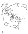
- FIG. 1 shows a schematic side view of a twin wire former 1 a machine for producing a fibrous web 2, in particular a paper or cardboard web, from at least one fiber suspension 3, with two revolving endless sieves (inner sieve 4, outer sieve 5), of which the inner sieve 4 over a peripheral region 6 of a preferably vacuumed forming roller 7 runs and the outer wire 5 over a peripheral region 8 of a breast roller 9 runs and then in the area of the forming roller 7 on the inner wire 4 with formation a wedge-shaped stock inlet gap 10, which is preferred by one Dilution water-controlled headbox 11 receives a fiber suspension 3, runs up and the two sieves (inner sieve 4, outer sieve 5) then form a twin wire section 12 which after the formation roll 7 below an angle ⁇ of -50 ° to + 50 ° (schematic range indication - / + ⁇ ) an imaginary vertical plane V runs down and at the end one Deflection device 13, in particular a deflection roller 13.1 is arranged the two screens 4, 5 in
- the two screens 4, 5 After the redirection and at the end of the twin wire section 12 run the two screens 4, 5 via a separating device 14, which the outer screen 5 separates from the fibrous web 2 formed and the inner wire 4.
- the outer screen 5 runs over guide rollers 15 back to the breast roller 9, whereas the inner wire 4 with the fibrous web 2 lying thereon to a not shown Pickup roller is guided before it then back to the forming roller via guide rollers 15 7 is running.
- twin wire former 1 shown here in accordance with the design of those already mentioned German published application DE 198 03 591 A1 (PB10656 DE) des
- the applicant can also implement the German version Published application DE 196 51 493 A1 (PB10449 DE) of the applicant his.
- the possible design of the twin wire former should not be limited to the embodiment according to FIG. 1, the embodiment According to FIG. 1, it is only intended as an exemplary character for a large number have possible design variants for the twin wire former.
- At least one machine-wide stripping device 16, in particular a machine-wide squeegee 16.1, between the forming roller 7 and the deflection device 13 is arranged such that it in the Immersed outer sieve 5 and that it the two sieves 4, 5 of one between the forming roller 7 and the deflection device 13 imaginary tangent T (dashed line) deflects towards the inner wire 4.
- the stripping device 16 has an immersion depth t in the outer screen 5 in the area from 0 mm to 10 mm, preferably from 1 mm to 7 mm, and a distance a from the running tangent point TP of the forming roller 7 in the range of 25 mm to 300 mm, preferably from 50 mm to 200 mm.
- the stripping device 16 further comprises a machine-wide stripping strip 16.1, which ideally has a strip width B in the range from 10 mm to 200 mm, preferably from 15 mm to 150 mm.
- the stripping device 16 with a collecting device 17, in particular a drip pan 17.1, to collect and to derive the by Scraper device 16 from the fibrous suspension 3 of dewatered white water 18 provided.
- the collecting device 17 can be closed in a further embodiment executed and with at least one preferably suctioned outlet be provided.
- the forming roller 7 of the twin wire former 1 has a diameter D F in the range from 1.0 m to 3.0 m, preferably from 1.2 m to 2.4 m, and a wrap angle ⁇ F in the range from 10 ° to 180 ° ,
- the deflection device 13 of the twin wire former 1 is designed as a deflection roller 13.1 and has a diameter D U in the range from 0.4 m to 2.4 m, preferably from 1.0 m to 1.8 m, and a wrap angle ⁇ U in the range from 50 ° to 180 °.
- the deflection device 13 is designed as a deflection roller 13.1 in the preferred form of an articulated roller or forming roller.
- FIG. 1A shows a schematic side view of a stripping device 16 of the twin wire former 1.
- the stripping device 16 has at least one closed, preferably extending into the region of the forming roller 7 Beam channel 19 has.
- the jet channel 19 is by means of a, not shown, however known and preferably controllable / adjustable vacuum device (Arrow) with negative pressure (-p) and / or with positive pressure (+ p), whereby he in the area of the forming roller 7 by means of at least one known scraper 20 and laterally sealed by means of at least one known gap seal 21 is.
- the stripping device 16 is of course in turn with a Collecting device 17 for collecting and for deriving through the stripping device 16 provided from the fiber suspension 3 dewatered white water 18.
- FIGS. 1B and 1C show two schematic and detailed side views of scraper devices 16 designed as scraper strips 1.6 Twin-wire former 1 according to the invention.
- the two scraper strips 16.1 each have an outlet angle ⁇ in the area from 2 ° to 45 °, preferably from 5 ° to 25 °.
- the stripping device 16 in particular the Squeegee 16.1
- the pressure preferably not explicitly by means of at least one shown, but known to those skilled in the art, for example in Shape of a cylinder, a spring element or a motor. It can be in further Execution of course also several, sectionally over the outer sieve 5 distributed actuators with possibly different settings be provided.
- FIG. 2 shows a further schematic and detailed side view of a Scraper device 16 of the twin wire former 1 according to the invention.
- the stripping device 16 is designed as a stripping strip 16.1, which has an inlet radius R 1 in the range from 0 mm to 100 mm, an arc length L B in the range from 3 mm to 15 mm and an outlet radius R 2 in the range from 2 m to 5 m , And again the outlet angle ⁇ formed on the scraper strip 16.1 can be seen in the range from 2 ° to 45 °, preferably from 5 ° to 25 °.
- FIGS. 2A and 2B show two detailed views of the squeegee 16.1 of Figure 2.
- the scraper strip 16.1 has a tip angle ⁇ in the range from 15 ° to 45 °, preferably from 25 ° to 35 °, and a tip radius R 3 in the range from 0.5 mm to 5 mm, preferably from 1 mm to 2 mm.
- the squeegee 16.1 can also have a tip chamfer (not shown), preferably with a flat surface.
- FIG. 3 shows a further schematic side view of the invention Twin wire former 1, which corresponds in principle to the embodiment of Figure 1. In this regard, reference is made to the description of FIG. 1.
- At least two stripping devices 16, 16A are provided are, with at least one stripping device 16, 16A in each Outer sieve 5 and immersed in the inner sieve 4.
- a total of two stripping devices 16, 16A are provided.
- the longitudinal axes I, II of the forming roller 7 and the deflection device 13 have a horizontal distance C which is in the range of +1.25 * diameter D F of the forming roller 7 (in the running direction L (arrow) - solid illustration) to -1, 25 * diameter D F of the forming roller 7 (against the running direction L (arrow) - dashed line).
- the inventive method for producing a fibrous web 2 can also be carried out with the twin-wire former 1 according to the invention.
- the two screens 4, 5 are deflected between the forming roller 7 and the deflecting device 13 by means of at least one machine-wide stripping device 16 from a tangent T between the forming roller 7 and the deflecting device 13 in the direction of the inner wire 4.
- the two screens 4, 5 are preferably in the range from 0 mm to 10 mm, in particular from 1 mm to 7 mm, from the imaginary tangent T and at a distance from the tangent point TP of the forming roller 7 in the range from 25 mm to 300 mm , preferably from 50 mm to 200 mm, deflected.
- the stripping device 30 comprises a housing 32 in which each other spaced apart three individual strips 33, 34, 35 in the direction of the outer sieve 5 are arranged.
- the upper and the forming roller 7 initially located bar 33 takes the measuring device 31.
- the strip 33 has a width of, for example between 10 and 180 mm.
- a trough-shaped discharge device 36 for Removal of white water arranged via an outlet 37.
- the housing 32 serves as a collecting trough for the stripped by the strips 33, 34, 35 from the screen 5
- White water that flows through an outlet 38, in particular by means of a suction pump, is derived.
- a separating suction device 39 is located below the housing 32 arranged, which serves to separate the fibrous web from the wire 4, so that it remains on the sieve 5.
- Another vacuum cleaner 40 is below one Fourdrinier wire 41 is arranged, onto which the fibrous web is transferred from the wire 5 becomes.
- the housing 32 has either a straight or one with respect to the sieve 5 curved shape, strips 33, 34, 35 have a corresponding shape.
- a measuring device 31 is in one Housing 42 arranged on the outer sieve 5.
- a pump 43 is white water sucked out of the housing 42.
- There are discharge devices on both sides of the screens 4, 5 44, 45, 46 arranged for discharging white water, each with pumps 44.1, 45.1, 46.1 or with drains to drain the into the trough-shaped discharge devices 44, 45, 46 collected white water are.
- a separating suction device 40 is present.
- the forming roller 7 is on the opposite side of the outer screen 5 in the running direction of the Fibrous suspension 3 arranged downstream of a stripping device 47.
- the contact pressure of a scraper strip 47.1 of the scraper device 47 becomes one Control device 48 supplied as an actual variable; this creates a target size for a pressure valve 49 for adjusting the pressure within a die Scraper device 47 surrounding housing 50 by means of compressed air or alternatively for direct adjustment of the contact pressure of the squeegee 47.1.
- a stripping device 51 with stripping strips 52, 53, 54 arranged within a housing 55.
- the squeegee 54 is with a measuring device 56 for measuring the suspension thickness; within of the housing 55 is the internal pressure via a control device 59 a pressure valve 57 for adjusting the pressure in the housing 55.
- the actual pressure is fed to the control device 59, which generates a target pressure generated for the pressure valve 57.
- the stripping device 51 opposite on the side of the outer sieve 5 are arranged elastically resilient strips 58 which the sieves 4, 5 and the fibrous web guided between them in their position opposite the Support scraper device 51.
- FIG. 7 which has the same structure as in FIG. 3 shown twin wire former with a deflection roller 13 are in the Scraper devices 16, 16A are scraper strips 60, 61 with sensors 62, 63 provided above tubs 65, 66 for the removal of white water.
- the measuring device is located in a protected environment in a Bar or in a housing. There is no additional for the measuring device Requires space. This avoids additional free screen lengths.
- the measuring device can be in a control device for controlling the Introduce suspension thickness, the suspension thickness either at the Position of the measuring device over the entire width or over individual Sections of the fibrous web width is regulated.
- the invention is a method and a twin wire former of the type mentioned with both a smaller one Screen wear compared to twin wire formers with forming shoes respectively a higher adhesion between the two sieves as well as one improved drainage performance compared to twin wire formers without forming shoes (Rollformer) is created.
Landscapes
- Paper (AREA)
- Nonwoven Fabrics (AREA)
- Preliminary Treatment Of Fibers (AREA)
Abstract
Description
- Figur 1:
- eine schematisierte Seitenansicht eines erfindungsgemäßen Doppelsiebformers;
- Figur 1A:
- eine schematisierte Seitenansicht einer Abstreifeinrichtung des erfindungsgemäßen Doppelsiebformers;
- Figuren 1B und 1C:
- zwei schematisierte und detaillierte Seitenansichten von Abstreifeinrichtungen des erfindungsgemäßen Doppelsiebformers;
- Figur 2:
- eine weitere schematisierte und detaillierte Seitenansicht einer Abstreifeinrichtung des erfindungsgemäßen Doppelsiebformers;
- Figuren 2A und 2B:
- zwei Detailansichten der Abstreifleiste der Figur 2;
- Figur 3:
- eine weitere schematisierte Seitenansicht des erfindungsgemäßen Doppelsiebformers; und
- Figuren 4 bis 7:
- weitere schematische Darstellungen eines Doppelsiebformers, in dem zusätzlich eine Messvorrichtung eingebracht ist.
Die beiden Siebe 4, 5 werden zwischen der Formierwalze 7 und der Umlenkeinrichtung 13 mittels mindestens einer maschinenbreiten Abstreifeinrichtung 16 von einer zwischen der Formierwalze 7 und der Umlenkeinrichtung 13 gedachten Tangente T in Richtung auf das Innensieb 4 abgelenkt. Dabei werden die beiden Siebe 4, 5 vorzugsweise im Bereich von 0 mm bis 10 mm, insbesondere von 1 mm bis 7 mm, von der gedachten Tangente T und in einem Abstand vom ablaufenden Tangentenpunkt TP der Formierwalze 7 im Bereich von 25 mm bis 300 mm, vorzugsweise von 50 mm bis 200 mm, abgelenkt.
- 1
- Doppelsiebformer
- 2
- Faserstoffbahn
- 3
- Faserstoffsuspension
- 4
- Innensieb
- 5
- Außensieb
- 6
- Umfangsbereich (Formierwalze)
- 7
- Formierwalze
- 8
- Umfangsbereich (Brustwalze)
- 9
- Brustwalze
- 9.1
- Brustformierwalze
- 9.2
- Offene Oberfläche
- 10
- Stoffeinlaufspalt
- 11
- Stoffauflauf
- 12
- Doppelsiebstrecke
- 13
- Umlenkeinrichtung
- 13.1
- Umlenkwalze
- 14
- Trenneinrichtung
- 15
- Leitwalze
- 16, 16A
- Abstreifeinrichtung
- 16.1
- Abstreifleiste
- 17
- Auffangeinrichtung
- 17.1
- Auffangwanne
- 18
- Siebwasser
- 19
- Strahlkanal
- 20
- Schaber
- 21
- Spaltdichtung
- 30
- Abstreifeinrichtung
- 31
- Messvorrichtung
- 32
- Gehäuse
- 33, 34, 35
- Leiste
- 36
- Abführeinrichtung
- 37
- Auslass
- 38
- Auslass
- 39,40
- Trennsauger
- 41
- Langsieb
- 42
- Gehäuse
- 43
- Pumpe
- 44, 45, 46
- Abführeinrichtung
- 44.1, 45.1, 46.1
- Pumpe
- 47
- Abstreifeinrichtung
- 47.1
- Abstreifleiste
- 48
- Regeleinrichtung
- 49
- Druckventil
- 50
- Gehäuse
- 51
- Abstreifeinrichtung
- 52, 53, 54
- Abstreifleiste
- 55
- Gehäuse
- 56
- Messeinrichtung
- 57
- Druckventil
- 58
- Leiste
- 59
- Regeleinrichtung
- 60,61
- Abstreifleiste
- 62, 63
- Messwertaufnehmer
- 65, 66
- Wanne
- a
- Abstand
- B
- Leistenbreite
- c
- Abstand
- d
- Abstand
- DF
- Durchmesser (Formierwalze)
- DU
- Durchmesser (Umlenkeinrichtung)
- E
- Andrückung (Richtungspfeil)
- I
- Längsachse (Formierwalze
- II
- Längsachse (Umlenkeinrichtung)
- L
- Laufrichtung (Pfeil)
- LB
- Bogenlänge
- - p
- Unterdruck
- R1
- Einlaufradius
- R2
- Auslaufradius
- R3
- Spitzenradius
- t
- Eintauchtiefe
- T
- Tangente
- TP
- Tangentenpunkt
- V
- Vertikalebene
- α
- Auslaufwinkel
- β
- Spitzenwinkel
- δ
- Winkel
- εF
- Umschlingungswinkel (Formierwalze)
- εU
- Umschlingungswinkel (Umlenkeinrichtung)
- +p
- Überdruck
Claims (33)
- Verfahren zur Herstellung einer Faserstoffbahn (2), insbesondere einer Papier- oder Kartonbahn, aus mindestens einer Faserstoffsuspension (3), mit zwei umlaufenden endlosen Sieben (Innensieb (4), Außensieb (5)), wobei das Innensieb (4) über einen Umfangsbereich (6) einer Formierwalze (7) geführt wird und das Außensieb (5) über einen Umfangsbereich (8) einer Brustwalze (9) geführt wird und danach im Bereich der Formierwalze (7) auf das Innensieb (4) unter Bildung eines keilförmigen Stoffeinlaufspalts (10), der unmittelbar von einem Stoffauflauf (11) eine Faserstoffsuspension (3) aufnimmt, geführt wird und anschließend eine Doppelsiebstrecke (12) durch die beiden Siebe (Innensieb (4), Außensieb (5)) gebildet wird, die nach Ablauf von der Formierwalze (7) unter einem Winkel (δ) von -50° bis +50° zu einer gedachten Vertikalebene (V) nach unten verläuft und an deren Ende eine Umlenkeinrichtung (13), insbesondere eine Umlenkwalze (13.1) angeordnet ist, mittels welcher mindestens eines der beiden Siebe (4, 5) in eine vorzugsweise im wesentlichen horizontale Laufrichtung (L) umgelenkt werden,
dadurch gekennzeichnet, dass die beiden Siebe (4, 5) zwischen der Formierwalze (7) und der Umlenkeinrichtung (13) mittels mindestens einer maschinenbreiten Abstreifeinrichtung (16) von einer zwischen der Formierwalze (7) und der Umlenkeinrichtung (13) gedachten Tangente (T) in Richtung auf das Innensieb (4) abgelenkt werden. - Verfahren nach Anspruch 1,
dadurch gekennzeichnet, dass die beiden Siebe (4, 5) im Bereich von 0 mm bis 10 mm, vorzugsweise von 1 mm bis 7 mm, von der gedachten Tangente (T) abgelenkt werden. - Verfahren nach Anspruch 1 oder 2,
dadurch gekennzeichnet, dass die beiden Siebe (4, 5) in einem Abstand (a) vom ablaufenden Tangentenpunkt (TP) der Formierwalze (7) im Bereich von 25 mm bis 300 mm, vorzugsweise von 50 mm bis 200 mm, abgelenkt werden. - Verfahren nach einem der Ansprüche 1 bis 3,
dadurch gekennzeichnet, dass die Suspensionsdicke der Faserstoffsuspension (3) gemessen wird, nachdem sie über die Formierwalze (7) in den Bereich zwischen den beiden Sieben (4, 5) eingebracht ist. - Verfahren nach Anspruch 4,
dadurch gekennzeichnet, dass die Suspensionsdicke durch eine Wellenstrahlung, insbesondere elektromagnetische Strahlung, insbesondere durch Licht, mittels Ultraschall oder durch Beta-Strahlung gemessen wird. - Doppelsiebformer (1) einer Maschine zur Herstellung einer Faserstoffbahn (2), insbesondere einer Papier- oder Kartonbahn, aus mindestens einer Faserstoffsuspension (3), mit zwei umlaufenden endlosen Sieben (Innensieb (4), Außensieb (5)), von denen das Innensieb (4) über einen Umfangsbereich (6) einer Formierwalze (7) läuft und das Außensieb (5) über einen Umfangsbereich (8) einer Brustwalze (9) läuft und danach im Bereich der Formierwalze (7) auf das Innensieb (4) unter Bildung eines keilförmigen Stoffeinlaufspalts (10), der unmittelbar von einem Stoffauflauf (11) eine Faserstoffsuspension (3) aufnimmt, aufläuft und die beiden Siebe (Innensieb (4), Außensieb (5)) anschließend eine Doppelsiebstrecke (12) bilden, die nach Ablauf von der Formierwalze (7) unter einem Winkel (δ) von -50° bis +50° zu einer gedachten Vertikalebene (V) nach unten verläuft und an deren Ende eine Umlenkeinrichtung (13), insbesondere eine Umlenkwalze (13.1) angeordnet ist, die mindestens eines der beiden Siebe (4, 5) in eine vorzugsweise im wesentlichen horizontale Laufrichtung (L) umlenkt,
dadurch gekennzeichnet, dass mindestens eine maschinenbreite Abstreifeinrichtung (16), insbesondere eine maschinenbreite Abstreifleiste (16.1), zwischen der Formierwalze (7) und der Umlenkeinrichtung (13) derart angeordnet ist, dass sie in das Außensieb (5) eintaucht und dass sie dabei die beiden Siebe (4, 5) von einer zwischen der Formierwalze (7) und der Umlenkeinrichtung (13) gedachten Tangente (T) in Richtung auf das Innensieb (4) ablenkt. - Doppelsiebformer (1) nach Anspruch 6,
dadurch gekennzeichnet, dass die Abstreifeinrichtung (16) eine Eintauchtiefe (t) in das Außensieb (5) im Bereich von 0 mm bis 10 mm, vorzugsweise von 1 mm bis 7 mm, aufweist. - Doppelsiebformer (1) nach Anspruch 6 oder 7,
dadurch gekennzeichnet, dass die Abstreifeinrichtung (16) einen Abstand (a) vom ablaufenden Tangentenpunkt der Formierwalze (7) im Bereich von 25 mm bis 300 mm, vorzugsweise von 50 mm bis 200 mm, aufweist. - Doppelsiebformer (1) nach einem der Ansprüche 6 bis 8,
dadurch gekennzeichnet, dass die Abstreifeinrichtung (16) mit einer Auffangeinrichtung (17), insbesondere einer Auffangwanne (17.1), zum Auffangen und zum Ableiten des durch die Abstreifeinrichtung (16) aus der Faserstoffsuspension (3) entwässerten Siebwassers (18) versehen ist. - Doppelsiebformer (1) nach einem der Ansprüche 6 bis 9,
dadurch gekennzeichnet, dass die Abstreifeinrichtung (16) mindestens einen geschlossenen, vorzugsweise sich bis in den Bereich der Formierwalze (7) erstreckenden Strahlkanal (19) aufweist. - Doppelsiebformer (1) nach Anspruch 10,
dadurch gekennzeichnet, dass der Strahlkanal (19) mit Unterdruck (-p) und/oder mit Überdruck (+p) beaufschlagbar ist, wobei er im Bereich der Formierwalze (7) mittels mindestens eines Schabers (20) und seitlich jeweils mittels mindestens einer Spaltdichtung (21) abgedichtet ist. - Doppelsiebformer (1) nach einem der Ansprüche 6 bis 11,
dadurch gekennzeichnet, dass die Abstreifeinrichtung (16) eine maschinenbreite Abstreifleiste (16.1) umfasst, die eine Leistenbreite (B) im Bereich von 10 mm bis 200 mm, vorzugsweise von 15 mm bis 150 mm, aufweist. - Doppelsiebformer (1) nach Anspruch 12,
dadurch gekennzeichnet, dass die Abstreifleiste (16.1) einen Einlaufradius (R1) im Bereich von 0 mm bis 100 mm, eine Bogenlänge (LB) im Bereich von 3 mm bis 15 mm und einen Auslaufradius (R2) im Bereich von 2 m bis 5 m aufweist. - Doppelsiebformer (1) nach Anspruch 12 oder 13,
dadurch gekennzeichnet, dass die Abstreifleiste (16.1) einen Spitzenwinkel (β) im Bereich von 15° bis 45°, vorzugsweise von 25° bis 35°, und eine Spitzenfase oder einen Spitzenradius (R3) im Bereich von 0,5 mm bis 5 mm, vorzugsweise von 1 mm bis 2 mm, aufweist. - Doppelsiebformer (1) nach einem der Ansprüche 6 bis 14,
dadurch gekennzeichnet, dass die Abstreifleiste (16.1) einen Auslaufwinkel (α) im Bereich von 2° bis 45°, vorzugsweise von 5° bis 25°, aufweist. - Doppelsiebformer (1) nach einem der Ansprüche 6 bis 15,
dadurch gekennzeichnet, dass die Abstreifeinrichtung (16), insbesondere die Abstreifleiste (16.1), elastisch an das Außensieb (5) andrückbar ist. - Doppelsiebformer (1) nach einem der Ansprüche 6 bis 16,
dadurch gekennzeichnet, dass mindestens zwei Abstreifeinrichtungen (16, 16A) vorgesehen sind, wobei mindestens je eine Abstreifeinrichtung (16, 16A) in das Außensieb (5) und in das Innensieb (4) eintaucht. - Doppelsiebformer (1) nach einem der Ansprüche 4 bis 15,
dadurch gekennzeichnet, dass die Formierwalze (7) des Doppelsiebformers (1) einen Durchmesser (DF) im Bereich von 1,0 m bis 3,0 m, vorzugsweise von 1,2 m bis 2,4 m, aufweist. - Doppelsiebformer (1) nach einem der Ansprüche 6 bis 18,
dadurch gekennzeichnet, dass die Formierwalze (7) des Doppelsiebformers (1) einen Umschlingungswinkel (εF) im Bereich von 10° bis 180° aufweist. - Doppelsiebformer (1) nach einem der Ansprüche 6 bis 19,
dadurch gekennzeichnet, dass die Umlenkeinrichtung (13) des Doppelsiebformers (1) als Umlenkwalze (13.1) ausgebildet ist und einen Durchmesser (DU) im Bereich von 0,4 m bis 2,4 m, vorzugsweise von 1,0 m bis 1,8 m, aufweist. - Doppelsiebformer (1) nach einem der Ansprüche 6 bis 20,
dadurch gekennzeichnet, dass die Umlenkeinrichtung (13) des Doppelsiebformers (1) einen Umschlingungswinkel (εU) im Bereich von 50° bis 180° aufweist. - Doppelsiebformer (1) nach einem der Ansprüche 6 bis 21,
dadurch gekennzeichnet, dass die Umlenkeinrichtung (13) als eine Umlenkwalze (13.1) in Form einer Knickwalze oder Formierwalze ausgebildet ist. - Doppelsiebformer (1) nach einem der Ansprüche 6 bis 22,
dadurch gekennzeichnet, dass die Längsachsen der Formierwalze (7) und der Umlenkeinrichtung (13) einen horizontalen Abstand (c) aufweisen, der im Bereich von +1,25 * Durchmesser (DF) der Formierwalze (7) (in Laufrichtung (L)) bis -1,25 * Durchmesser (DF) der Formierwalze (7) (entgegen der Laufrichtung (L)) liegt. - Doppelsiebformer (1) nach einem der Ansprüche 6 bis 23,
dadurch gekennzeichnet, dass der Formierwalze (7) in Laufrichtung L (Pfeil) der Faserstoffsuspension (3) eine Messvorrichtung (31, 56) zum Messen der Suspensionsdicke der Faserstoffsuspension (3) nachgeordnet ist. - Doppelsiebformer (1) nach Anspruch 24,
dadurch gekennzeichnet, dass die Messvorrichtung (31, 56) vor einem in Laufrichtung L (Pfeil) der Faserstoffsuspension (3) nachgeordneten Leistenteil an dem Innensieb (4) oder dem Außensieb (5) angeordnet ist. - Doppelsiebformer (1) nach Anspruch 24 oder 25,
dadurch gekennzeichnet, dass die Messvorrichtung (31, 56) in einem Gehäuse (32) angeordnet ist, in dem mindestens eine Leiste (33, 34, 35, 58) mit mindestens einem Messwertaufnehmer (62, 63) angeordnet ist. - Doppelsiebformer (1) nach einem der Ansprüche 24 bis 26,
dadurch gekennzeichnet, dass die das Gehäuse (32, 50) bzw. die Messvorrichtung (31, 56) umfassende Abstreifeinrichung (47, 51) mit einer Einrichtung (59) zum Einstellen eines Unterdrucks verbunden ist, durch die ein Unterdruck anlegbar ist. - Doppelsiebformer (1) nach einem der Ansprüche 24 bis 27,
dadurch gekennzeichnet, dass die mindestens eine Leiste (33, 34, 35, 58) ortsfest oder elastisch an das Innensieb (4) bzw. das Außensieb (5) anpressbar oder ausschließlich bei einem Messvorgang an das Innensieb (4) bzw. das Außensieb (5) anpressbar ist. - Doppelsiebformer (1) nach einem der Ansprüche 24 bis 28,
dadurch gekennzeichnet, dass die von der Messvorrichtung (31, 56) gemessene Suspensionsdicke einer Regelvorrichtung (59) zur Regelung einer konstanten Suspensionsdicke zuführbar ist und
dass durch die Regelvorrichtung durch Änderung eines Parameters des Doppelsiebformers (1), insbesondere des Unterdrucks in der Formierwalze (7) und/oder in einem ersten Schuhteil, die Suspensionsdicke regelbar ist. - Doppelsiebformer (1) nach Anspruch 29,
dadurch gekennzeichnet, dass über die Breite des Doppelsiebformers (1) eine Mehrzahl von einzeln und unabhängig von einander verstellbaren Bereichen, insbesondere in der Formierwalze (7) vorhanden ist, in denen die Suspensionsdicke einstellbar ist. - Doppelsiebformer (1) nach einem der Ansprüche 6 bis 30,
dadurch gekennzeichnet, dass der Messvorrichtung (31, 56) eine weitere Walze, insbesondere eine Umlenkwalze (13.1) und/oder eine Saugwalze, oder eine von beiden Sieben (4, 5) umschlungene Knickwalze nachgeordnet ist. - Doppelsiebformer (1) nach einem der Ansprüche 23 bis 31,
dadurch gekennzeichnet, dass die Messvorrichtung (31, 56) eine Spülvorrichtung und/oder eine Reinigungsvorrichtung umfasst. - Doppelsiebformer (1) nach einem der Ansprüche 23 bis 32,
dadurch gekennzeichnet, dass an der Messvorrichtung (31) eine Beleuchtungseinrichtung angeordnet ist.
Applications Claiming Priority (4)
| Application Number | Priority Date | Filing Date | Title |
|---|---|---|---|
| DE2002142564 DE10242564A1 (de) | 2002-09-13 | 2002-09-13 | Verfahren und Doppelsiebformer einer Maschine zur Herstellung einer Faserstoffbahn |
| DE10242564 | 2002-09-13 | ||
| DE10303464 | 2003-01-29 | ||
| DE2003103464 DE10303464A1 (de) | 2003-01-29 | 2003-01-29 | Verfahren und Doppelsiebformer einer Maschine zur Herstellung einer Faserstoffbahn |
Publications (2)
| Publication Number | Publication Date |
|---|---|
| EP1398412A1 true EP1398412A1 (de) | 2004-03-17 |
| EP1398412B1 EP1398412B1 (de) | 2008-02-13 |
Family
ID=31889107
Family Applications (1)
| Application Number | Title | Priority Date | Filing Date |
|---|---|---|---|
| EP03102717A Expired - Lifetime EP1398412B1 (de) | 2002-09-13 | 2003-09-05 | Doppelsiebformer zur Herstellung einer Faserstoffbahn |
Country Status (3)
| Country | Link |
|---|---|
| EP (1) | EP1398412B1 (de) |
| AT (1) | ATE386155T1 (de) |
| DE (1) | DE50309144D1 (de) |
Cited By (1)
| Publication number | Priority date | Publication date | Assignee | Title |
|---|---|---|---|---|
| WO2006091165A1 (en) * | 2005-02-28 | 2006-08-31 | Stfi-Packforsk Ab | Dewatering apparatus |
Families Citing this family (1)
| Publication number | Priority date | Publication date | Assignee | Title |
|---|---|---|---|---|
| DE102017119526B4 (de) | 2017-08-25 | 2021-02-25 | Joh. Clouth GmbH & Co KG | Vorrichtung zum Halten von Schaberklingen |
Citations (5)
| Publication number | Priority date | Publication date | Assignee | Title |
|---|---|---|---|---|
| US3432385A (en) * | 1965-12-15 | 1969-03-11 | Huyck Corp | Water extraction devices |
| EP0761874A2 (de) * | 1995-08-23 | 1997-03-12 | Voith Sulzer Papiermaschinen GmbH | Vorrichtung zum Herstellen eines mehrlagigen Papiers oder Kartons |
| DE19709294A1 (de) * | 1997-03-07 | 1998-09-10 | Voith Sulzer Papiermasch Gmbh | Siebpartie und Verfahren zur Blattbildung in einer Siebpartie |
| DE19803591A1 (de) * | 1998-01-30 | 1999-08-05 | Voith Sulzer Papiertech Patent | Doppelsieb-Former |
| WO2001098581A1 (en) * | 2000-06-12 | 2001-12-27 | Metso Paper, Inc. | Method and regulation arrangement for controlling dewatering profile of a former |
-
2003
- 2003-09-05 AT AT03102717T patent/ATE386155T1/de active
- 2003-09-05 EP EP03102717A patent/EP1398412B1/de not_active Expired - Lifetime
- 2003-09-05 DE DE50309144T patent/DE50309144D1/de not_active Expired - Lifetime
Patent Citations (5)
| Publication number | Priority date | Publication date | Assignee | Title |
|---|---|---|---|---|
| US3432385A (en) * | 1965-12-15 | 1969-03-11 | Huyck Corp | Water extraction devices |
| EP0761874A2 (de) * | 1995-08-23 | 1997-03-12 | Voith Sulzer Papiermaschinen GmbH | Vorrichtung zum Herstellen eines mehrlagigen Papiers oder Kartons |
| DE19709294A1 (de) * | 1997-03-07 | 1998-09-10 | Voith Sulzer Papiermasch Gmbh | Siebpartie und Verfahren zur Blattbildung in einer Siebpartie |
| DE19803591A1 (de) * | 1998-01-30 | 1999-08-05 | Voith Sulzer Papiertech Patent | Doppelsieb-Former |
| WO2001098581A1 (en) * | 2000-06-12 | 2001-12-27 | Metso Paper, Inc. | Method and regulation arrangement for controlling dewatering profile of a former |
Cited By (1)
| Publication number | Priority date | Publication date | Assignee | Title |
|---|---|---|---|---|
| WO2006091165A1 (en) * | 2005-02-28 | 2006-08-31 | Stfi-Packforsk Ab | Dewatering apparatus |
Also Published As
| Publication number | Publication date |
|---|---|
| DE50309144D1 (de) | 2008-03-27 |
| ATE386155T1 (de) | 2008-03-15 |
| EP1398412B1 (de) | 2008-02-13 |
Similar Documents
| Publication | Publication Date | Title |
|---|---|---|
| DE69308904T2 (de) | Blattbildungspartie für eine Papiermaschine | |
| DE69221034T2 (de) | Siebbelastungsvorrichtung in einer Papiermaschine | |
| DE69020106T2 (de) | Doppelsiebformer in einer Papiermaschine. | |
| EP0486814B1 (de) | Nassteil einer Doppelsieb-Papiermaschine | |
| EP0837181B1 (de) | Pressenpartie | |
| DE69713104T2 (de) | Doppelsiebformer für eine papiermaschine | |
| EP0454989A1 (de) | Vertikalformer | |
| EP0761874A2 (de) | Vorrichtung zum Herstellen eines mehrlagigen Papiers oder Kartons | |
| DE69426169T2 (de) | Blattbildungspartie in einer Papiermaschine | |
| DE69110260T2 (de) | Doppelsiebformer in einer Papiermaschine. | |
| EP1398412B1 (de) | Doppelsiebformer zur Herstellung einer Faserstoffbahn | |
| DE3107730A1 (de) | "doppelsiebpartie" | |
| WO1995008669A1 (de) | Doppelsiebformer einer papiermaschine | |
| DE10303464A1 (de) | Verfahren und Doppelsiebformer einer Maschine zur Herstellung einer Faserstoffbahn | |
| EP0831172B1 (de) | Siebpartie und Verfahren zum Entwässern einer Faserstoffbahn in einer Siebpartie | |
| EP1953296B1 (de) | Verfahren zur Herstellung einer Faserstoffbahn und Doppelsiebformer zur Durchführung des Verfahrens | |
| DE19803451A1 (de) | Naßpartie und Verfahren zum Herstellen einer Faserstoffbahn | |
| EP4328376B1 (de) | Schrägsiebformer | |
| DE60213359T2 (de) | Vorrichtung zur Herstellung einer Papier- oder Pappebahn | |
| DE10242564A1 (de) | Verfahren und Doppelsiebformer einer Maschine zur Herstellung einer Faserstoffbahn | |
| EP1586702B1 (de) | Doppelsiebformer für eine Maschine zur Herstellung einer Faserstoffbahn | |
| EP1426488A1 (de) | Vorrichtung zur Herstellung einer Faserstoffbahn | |
| DE2647295C3 (de) | Papiermaschine | |
| EP0824159A2 (de) | Verfahren und Vorrichtung zum Herstellen einer Faserstoffbahn | |
| DE9201722U1 (de) | Doppelsiebpartie für eine Papiermaschine |
Legal Events
| Date | Code | Title | Description |
|---|---|---|---|
| PUAI | Public reference made under article 153(3) epc to a published international application that has entered the european phase |
Free format text: ORIGINAL CODE: 0009012 |
|
| AK | Designated contracting states |
Kind code of ref document: A1 Designated state(s): AT BE BG CH CY CZ DE DK EE ES FI FR GB GR HU IE IT LI LU MC NL PT RO SE SI SK TR |
|
| AX | Request for extension of the european patent |
Extension state: AL LT LV MK |
|
| 17P | Request for examination filed |
Effective date: 20040917 |
|
| AKX | Designation fees paid |
Designated state(s): AT BE BG CH CY CZ DE DK EE ES FI FR GB GR HU IE IT LI LU MC NL PT RO SE SI SK TR |
|
| RAP1 | Party data changed (applicant data changed or rights of an application transferred) |
Owner name: VOITH PATENT GMBH |
|
| RTI1 | Title (correction) |
Free format text: TWIN WIRE FORMER FOR PRODUCING A FIBROUS WEB |
|
| GRAP | Despatch of communication of intention to grant a patent |
Free format text: ORIGINAL CODE: EPIDOSNIGR1 |
|
| GRAS | Grant fee paid |
Free format text: ORIGINAL CODE: EPIDOSNIGR3 |
|
| GRAA | (expected) grant |
Free format text: ORIGINAL CODE: 0009210 |
|
| AK | Designated contracting states |
Kind code of ref document: B1 Designated state(s): AT BE BG CH CY CZ DE DK EE ES FI FR GB GR HU IE IT LI LU MC NL PT RO SE SI SK TR |
|
| REG | Reference to a national code |
Ref country code: GB Ref legal event code: FG4D Free format text: NOT ENGLISH |
|
| REG | Reference to a national code |
Ref country code: CH Ref legal event code: EP |
|
| REG | Reference to a national code |
Ref country code: IE Ref legal event code: FG4D Free format text: LANGUAGE OF EP DOCUMENT: GERMAN |
|
| REF | Corresponds to: |
Ref document number: 50309144 Country of ref document: DE Date of ref document: 20080327 Kind code of ref document: P |
|
| REG | Reference to a national code |
Ref country code: SE Ref legal event code: TRGR |
|
| PG25 | Lapsed in a contracting state [announced via postgrant information from national office to epo] |
Ref country code: ES Free format text: LAPSE BECAUSE OF FAILURE TO SUBMIT A TRANSLATION OF THE DESCRIPTION OR TO PAY THE FEE WITHIN THE PRESCRIBED TIME-LIMIT Effective date: 20080524 |
|
| NLV1 | Nl: lapsed or annulled due to failure to fulfill the requirements of art. 29p and 29m of the patents act | ||
| PG25 | Lapsed in a contracting state [announced via postgrant information from national office to epo] |
Ref country code: SI Free format text: LAPSE BECAUSE OF FAILURE TO SUBMIT A TRANSLATION OF THE DESCRIPTION OR TO PAY THE FEE WITHIN THE PRESCRIBED TIME-LIMIT Effective date: 20080213 |
|
| REG | Reference to a national code |
Ref country code: IE Ref legal event code: FD4D |
|
| PG25 | Lapsed in a contracting state [announced via postgrant information from national office to epo] |
Ref country code: CZ Free format text: LAPSE BECAUSE OF FAILURE TO SUBMIT A TRANSLATION OF THE DESCRIPTION OR TO PAY THE FEE WITHIN THE PRESCRIBED TIME-LIMIT Effective date: 20080213 Ref country code: DK Free format text: LAPSE BECAUSE OF FAILURE TO SUBMIT A TRANSLATION OF THE DESCRIPTION OR TO PAY THE FEE WITHIN THE PRESCRIBED TIME-LIMIT Effective date: 20080213 Ref country code: IE Free format text: LAPSE BECAUSE OF FAILURE TO SUBMIT A TRANSLATION OF THE DESCRIPTION OR TO PAY THE FEE WITHIN THE PRESCRIBED TIME-LIMIT Effective date: 20080213 Ref country code: NL Free format text: LAPSE BECAUSE OF FAILURE TO SUBMIT A TRANSLATION OF THE DESCRIPTION OR TO PAY THE FEE WITHIN THE PRESCRIBED TIME-LIMIT Effective date: 20080213 Ref country code: SK Free format text: LAPSE BECAUSE OF FAILURE TO SUBMIT A TRANSLATION OF THE DESCRIPTION OR TO PAY THE FEE WITHIN THE PRESCRIBED TIME-LIMIT Effective date: 20080213 Ref country code: PT Free format text: LAPSE BECAUSE OF FAILURE TO SUBMIT A TRANSLATION OF THE DESCRIPTION OR TO PAY THE FEE WITHIN THE PRESCRIBED TIME-LIMIT Effective date: 20080714 |
|
| PG25 | Lapsed in a contracting state [announced via postgrant information from national office to epo] |
Ref country code: RO Free format text: LAPSE BECAUSE OF FAILURE TO SUBMIT A TRANSLATION OF THE DESCRIPTION OR TO PAY THE FEE WITHIN THE PRESCRIBED TIME-LIMIT Effective date: 20080213 |
|
| EN | Fr: translation not filed | ||
| PLBE | No opposition filed within time limit |
Free format text: ORIGINAL CODE: 0009261 |
|
| STAA | Information on the status of an ep patent application or granted ep patent |
Free format text: STATUS: NO OPPOSITION FILED WITHIN TIME LIMIT |
|
| 26N | No opposition filed |
Effective date: 20081114 |
|
| BERE | Be: lapsed |
Owner name: VOITH PATENT G.M.B.H. Effective date: 20080930 |
|
| PG25 | Lapsed in a contracting state [announced via postgrant information from national office to epo] |
Ref country code: EE Free format text: LAPSE BECAUSE OF FAILURE TO SUBMIT A TRANSLATION OF THE DESCRIPTION OR TO PAY THE FEE WITHIN THE PRESCRIBED TIME-LIMIT Effective date: 20080213 Ref country code: BG Free format text: LAPSE BECAUSE OF FAILURE TO SUBMIT A TRANSLATION OF THE DESCRIPTION OR TO PAY THE FEE WITHIN THE PRESCRIBED TIME-LIMIT Effective date: 20080513 Ref country code: FR Free format text: LAPSE BECAUSE OF FAILURE TO SUBMIT A TRANSLATION OF THE DESCRIPTION OR TO PAY THE FEE WITHIN THE PRESCRIBED TIME-LIMIT Effective date: 20081205 Ref country code: MC Free format text: LAPSE BECAUSE OF NON-PAYMENT OF DUE FEES Effective date: 20080930 |
|
| REG | Reference to a national code |
Ref country code: CH Ref legal event code: PL |
|
| GBPC | Gb: european patent ceased through non-payment of renewal fee |
Effective date: 20080905 |
|
| PG25 | Lapsed in a contracting state [announced via postgrant information from national office to epo] |
Ref country code: CY Free format text: LAPSE BECAUSE OF FAILURE TO SUBMIT A TRANSLATION OF THE DESCRIPTION OR TO PAY THE FEE WITHIN THE PRESCRIBED TIME-LIMIT Effective date: 20080213 Ref country code: BE Free format text: LAPSE BECAUSE OF NON-PAYMENT OF DUE FEES Effective date: 20080930 |
|
| PG25 | Lapsed in a contracting state [announced via postgrant information from national office to epo] |
Ref country code: CH Free format text: LAPSE BECAUSE OF NON-PAYMENT OF DUE FEES Effective date: 20080930 Ref country code: LI Free format text: LAPSE BECAUSE OF NON-PAYMENT OF DUE FEES Effective date: 20080930 |
|
| PG25 | Lapsed in a contracting state [announced via postgrant information from national office to epo] |
Ref country code: GB Free format text: LAPSE BECAUSE OF NON-PAYMENT OF DUE FEES Effective date: 20080905 |
|
| PG25 | Lapsed in a contracting state [announced via postgrant information from national office to epo] |
Ref country code: LU Free format text: LAPSE BECAUSE OF NON-PAYMENT OF DUE FEES Effective date: 20080905 Ref country code: HU Free format text: LAPSE BECAUSE OF FAILURE TO SUBMIT A TRANSLATION OF THE DESCRIPTION OR TO PAY THE FEE WITHIN THE PRESCRIBED TIME-LIMIT Effective date: 20080814 |
|
| PG25 | Lapsed in a contracting state [announced via postgrant information from national office to epo] |
Ref country code: TR Free format text: LAPSE BECAUSE OF FAILURE TO SUBMIT A TRANSLATION OF THE DESCRIPTION OR TO PAY THE FEE WITHIN THE PRESCRIBED TIME-LIMIT Effective date: 20080213 |
|
| PG25 | Lapsed in a contracting state [announced via postgrant information from national office to epo] |
Ref country code: GR Free format text: LAPSE BECAUSE OF FAILURE TO SUBMIT A TRANSLATION OF THE DESCRIPTION OR TO PAY THE FEE WITHIN THE PRESCRIBED TIME-LIMIT Effective date: 20080514 |
|
| PGFP | Annual fee paid to national office [announced via postgrant information from national office to epo] |
Ref country code: DE Payment date: 20110923 Year of fee payment: 9 Ref country code: FI Payment date: 20110914 Year of fee payment: 9 Ref country code: AT Payment date: 20110914 Year of fee payment: 9 Ref country code: SE Payment date: 20110923 Year of fee payment: 9 |
|
| PGFP | Annual fee paid to national office [announced via postgrant information from national office to epo] |
Ref country code: IT Payment date: 20110926 Year of fee payment: 9 |
|
| PG25 | Lapsed in a contracting state [announced via postgrant information from national office to epo] |
Ref country code: SE Free format text: LAPSE BECAUSE OF NON-PAYMENT OF DUE FEES Effective date: 20120906 Ref country code: FI Free format text: LAPSE BECAUSE OF NON-PAYMENT OF DUE FEES Effective date: 20120905 |
|
| REG | Reference to a national code |
Ref country code: SE Ref legal event code: EUG |
|
| REG | Reference to a national code |
Ref country code: AT Ref legal event code: MM01 Ref document number: 386155 Country of ref document: AT Kind code of ref document: T Effective date: 20120905 |
|
| PG25 | Lapsed in a contracting state [announced via postgrant information from national office to epo] |
Ref country code: AT Free format text: LAPSE BECAUSE OF NON-PAYMENT OF DUE FEES Effective date: 20120905 Ref country code: DE Free format text: LAPSE BECAUSE OF NON-PAYMENT OF DUE FEES Effective date: 20130403 |
|
| REG | Reference to a national code |
Ref country code: DE Ref legal event code: R119 Ref document number: 50309144 Country of ref document: DE Effective date: 20130403 |
|
| PG25 | Lapsed in a contracting state [announced via postgrant information from national office to epo] |
Ref country code: IT Free format text: LAPSE BECAUSE OF NON-PAYMENT OF DUE FEES Effective date: 20120905 |