EP1398137A1 - Laminierstempel mit einem Laminierelement aus elastischem Material, Laminierpresse und Verfahren - Google Patents
Laminierstempel mit einem Laminierelement aus elastischem Material, Laminierpresse und Verfahren Download PDFInfo
- Publication number
- EP1398137A1 EP1398137A1 EP03019640A EP03019640A EP1398137A1 EP 1398137 A1 EP1398137 A1 EP 1398137A1 EP 03019640 A EP03019640 A EP 03019640A EP 03019640 A EP03019640 A EP 03019640A EP 1398137 A1 EP1398137 A1 EP 1398137A1
- Authority
- EP
- European Patent Office
- Prior art keywords
- laminating
- core part
- stamp
- lateral
- panel
- Prior art date
- Legal status (The legal status is an assumption and is not a legal conclusion. Google has not performed a legal analysis and makes no representation as to the accuracy of the status listed.)
- Granted
Links
Images

Classifications
-
- B—PERFORMING OPERATIONS; TRANSPORTING
- B32—LAYERED PRODUCTS
- B32B—LAYERED PRODUCTS, i.e. PRODUCTS BUILT-UP OF STRATA OF FLAT OR NON-FLAT, e.g. CELLULAR OR HONEYCOMB, FORM
- B32B37/00—Methods or apparatus for laminating, e.g. by curing or by ultrasonic bonding
- B32B37/10—Methods or apparatus for laminating, e.g. by curing or by ultrasonic bonding characterised by the pressing technique, e.g. using action of vacuum or fluid pressure
-
- B—PERFORMING OPERATIONS; TRANSPORTING
- B29—WORKING OF PLASTICS; WORKING OF SUBSTANCES IN A PLASTIC STATE IN GENERAL
- B29C—SHAPING OR JOINING OF PLASTICS; SHAPING OF MATERIAL IN A PLASTIC STATE, NOT OTHERWISE PROVIDED FOR; AFTER-TREATMENT OF THE SHAPED PRODUCTS, e.g. REPAIRING
- B29C63/00—Lining or sheathing, i.e. applying preformed layers or sheathings of plastics; Apparatus therefor
- B29C63/02—Lining or sheathing, i.e. applying preformed layers or sheathings of plastics; Apparatus therefor using sheet or web-like material
- B29C63/16—Lining or sheathing, i.e. applying preformed layers or sheathings of plastics; Apparatus therefor using sheet or web-like material applied by "rubber" bag or diaphragm
-
- B—PERFORMING OPERATIONS; TRANSPORTING
- B30—PRESSES
- B30B—PRESSES IN GENERAL
- B30B5/00—Presses characterised by the use of pressing means other than those mentioned in the preceding groups
- B30B5/02—Presses characterised by the use of pressing means other than those mentioned in the preceding groups wherein the pressing means is in the form of a flexible element, e.g. diaphragm, urged by fluid pressure
Definitions
- the present invention relates to a laminating stamp for laminating.
- the invention relates to a such a laminating stamp, the lateral emigration of a Laminating element prevents away from the object to be laminated.
- Laminating punches are used in laminating presses to objects to connect with a panel in the lamination process.
- the objects are usually core parts made of plastic or metal, on which a cover plate is used for decorative reasons to be put on.
- the cover plate can processed sheet metal, plastic, wood veneer or similar consist.
- the laminating stamps consist of a Base plate as a holder on which a laminating element made of rubber or a similar elastic material, is glued on.
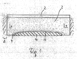
- FIG. 1 shows such a previously known laminating stamp a laminating element 3 and a laminating element holder 2, wherein the laminating element 3 also has a recess 4 has the depth and dimensions of the element to be laminated, for example an aperture 20 is adjusted.
- the laminating stamp is like this for lamination on the aperture plate 20, which is placed on the core part 10 is, that the aperture 20 is exactly in the formation 4 comes to rest.
- core part 10 and aperture plate 20 together laminated.
- Laminating stamps for a lateral migration of the elastic Mass of the laminating element 3, as in Fig. 1 by the dashed area is shown, and thus to a lateral expansion of the formation 4, which is no longer on side areas of the panel 20 or the core part 10, can concern.
- a lamination leading around the core part Core part edges are not possible because there is no pressure on these edges and the corresponding side areas of the Aperture plate 20 can be exercised. It is not that possible to produce laminate pieces that are also correct laterally are laminated. The production of such laminate pieces however, is desirable to look at even from the side the panel to be produced is an aesthetically pleasing view on the faceplate and not on the more functional than to grant aesthetically designed core part.
- the invention is based on the principle, the lateral one Limit migration of the elastic laminating element or completely to prevent lateral pressure to be able to exert on the aperture plate.
- the laminating element can be attached laterally to the movement stops. Because a lateral movement of the laminating element made of elastic material prevented by the limiter can, at least on the limited sides, no longer move the shape laterally, so that the shape is also on the side of the Aperture remains attached and appropriate pressure is applied can exercise this. This also allows the side area of the Aperture plate when using the laminating stamp according to the invention to be laminated with or at least one shape the aperture plate can be reached or obtained for the aesthetic appearance of the entire piece of laminate is desirable is.
- At least one side limiter be or have a plate attached to a side wall of the laminating element is attached and up to Forming is enough.
- the delimiter represents for the entire side wall of the elastic laminating element between the laminating element holder and its underside (i.e. the side with the recess) represents an abutment that the lateral movement of the elastic laminating element in toto prevents.
- An elastic evasion of the lamination element mass is therefore only on the one hand in the direction Aperture, which benefits lamination printing, and on the other hand possible in the direction of the side of the laminating plate, what due to the forces that occur the pressure on the side area the aperture still improved.
- the lateral limiter can also have a pressure element, the side of a side wall of the laminating element is arranged in the area of the formation and in the area prevents sideways movement of the formation.
- the delimiter does not have to be complete plate covering the side wall, but can only on part of the side wall of the laminating element issue.
- the parts of the side portion of the elastic laminating member still possible, not by the pressure element of the delimiter are fixed. This can be for certain applications be desirable provided there is some lateral compliance should be preserved. By preventing one lateral movement in the area to the side of the formation however, continued side pressure on the side areas the aperture plate ensured.
- the at least one limiter and the laminating element holder can be made in one piece, for example they are formed from a piece of metal, punching or Casting are exemplary manufacturing processes. Others too Materials can be used to manufacture the limiter and / or of the laminating element holder, if they are in the Are able, that exerted on the laminating element holder Pressure and the pressure from the laminator to the limiter is passed on to record without having an acceptable Dimension to be impaired in their shape.
- An embodiment is particularly preferred in which Side limiters are arranged on each side of the laminating element are and laminating element holder and side delimiter form a tub in which the laminating element is flush is used.
- the limiter attached to the side wall of the laminating element can be glued to it, but it is also possible that the side wall of the laminating element and the lateral limiters attached to it are movable relative to each other are. Depending on the requirements of the still desirable and undesirable movement of the side area of the laminating element can be one or the other embodiment to get voted. In many cases it becomes a complete one Elimination of lateral movement and thus an additional one Attachment by gluing or the like be desirable.
- the invention is further directed to a laminating press. Everything about the laminating stamp above also applies to the laminating press and vice versa.
- the pressure generator will usually be a plunger acts on the laminating element holder.
- the laminating press can be a standardized one Press of common design include, but different from this differs in that the laminating stamp according to the invention is inserted into it.
- the invention is directed to a method the characteristics and aspects of the lamination stamp as well apply to the procedure, so that alternate reference is taken.
- the method can also be modified so that the adhesive on the at least one edge of the core part is applied to which the side region of the diaphragm plate is attachable, and by applying pressure the side portions of the edge is laminated.
- the side area is not remains only in an appropriate form, but through the The lamination process can keep this shape even if the laminate product, for example due to temperature changes etc. is exposed to certain movements.
- the Aperture plate consist of a material which by Pressure of the laminating element can be bent. It will be on At the beginning of the process, insert an orifice plate, which is flat or only slightly arched, at least on its side area has no bulge. Only through the pressure the through the laminating element on the aperture plate during of the lamination is carried out, the side portion of the Aperture plate bent into the final shape and stored to the edge of the core part. That way, a suitable material for the cover plate provided one processing step can be saved since one previously making an overturned side portion in the cover plate is not necessary.
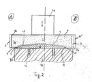
- FIG. 2 are two alternative embodiments A and B shown.
- A shows a workpiece to be laminated, which consists of a core part 10, an aperture 20 and an intermediate layer of an adhesive consists.
- the arrangement is on a suitable workpiece holder 40 placed, the representation of the workpiece holder in Fig. 2 is only exemplary.
- the core part 10 has an edge 11 and holder in addition to its main element 12 for later attachment of the finished piece of laminate on a surface.
- the laminating stamp worked according to the invention is placed on the bezel.
- the aperture can made of any suitable material, e.g. made of veneer wood, a decorative plate made of metal or plastic or also a fabric, leather or foil or other lamination.
- a formation 4 is provided in the laminating element 3, which, in terms of its shape and dimensions, exactly matches the shape of the Workpiece that is to be laminated. Also the Formation 4 has side areas 5, which a print should exert on side regions 21 of the core part 10.
- limiters 6 are provided that exactly on the side wall surface 3b of the laminating element and with the laminating element holder 2 welded, glued or other suitable Way connected.
- FIG. 2 In the right area of FIG. 2 is a variant B shown, in which instead of a plate-shaped limiter 6 a limiter 6 'is used, which has a pressure area 7a has, which is approximately at the level of the formation 4 of the Laminating element 3 is located and a lateral evasion the lateral areas of the laminating element 3 as well how a plate 6 can prevent as a limiter.
- a limiter 6 ' which has a pressure area 7a has, which is approximately at the level of the formation 4 of the Laminating element 3 is located and a lateral evasion the lateral areas of the laminating element 3 as well how a plate 6 can prevent as a limiter.
- a plate 6 it is possible that it is further away from the formation 4 Areas of the laminating element 3 still a lateral one Can experience movement.
- This is defined by a Choice of the free space 7 allows a predetermined capacity for alternative material of the laminating element 3 has before an increased pressure build-up on the Side area
- the Core part 10 has an edge 11, which when laminated Piece with adhesive 31 with the side area 21 the panel 20 is laminated. This way it can be achieve that even on the side area of the laminate piece the bezel is securely laminated so that the optical Impression improves and the durability of the laminate piece can be enlarged because a sticking out is avoided becomes.
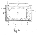
- FIG. 4 shows the bottom view of a laminating stamp according to the invention, where like reference numerals like elements denote the invention.
- the exemplary oval-shaped Formation 4 is located approximately in the middle of the laminating element 3.
- the circulation areas 8 can each extend over the entire side edge 9 so that this creates a tub structure the laminating element holder 2 and the limiter 6, 8 results and so if necessary also a lateral pressure over the entire length can be put.
Landscapes
- Engineering & Computer Science (AREA)
- Physics & Mathematics (AREA)
- Fluid Mechanics (AREA)
- Manufacturing & Machinery (AREA)
- Mechanical Engineering (AREA)
- Laminated Bodies (AREA)
Abstract
Description
- Fig. 1
- zeigt einen konventionellen Laminierstempel mit einem in der dortigen Ausformung befindlichen Laminierstück;
- Fig. 2
- zeigt eine erste Ausführungsform eines Laminierstempels gemäß der vorliegenden Erfindung;
- Fig. 3
- zeigt ein Detail des Seitenbereichs der Blendenplatte und des Kernteils zur Verdeutlichung des gewünschten seitlichen Anlagerns des Seitenbereichs an den Kernteil; und
- Fig. 4
- zeigt in Aufsicht eine weitere Ausführungsform eines Laminierstempels gemäß der vorliegenden Erfindung.
Claims (13)
- Laminierstempel zum Laminieren eines Werkstücks, das zumindest aus einem Kernteil (10) und einer Blende (20) besteht, die das Kernteil bedeckt, das zumindest einen Seitenbereich (21) aufweist, an den zumindest ein Teil der Blende anlagerbar ist, mit
einem elastischen Laminierelement (3), in dem eine Ausformung (4) ausgebildet ist mit
einem Laminierelementhalter (2);
gekennzeichnet durch zumindest einen, am Laminierelementhalter (2) angeordneten, seitlichen Begrenzer (6, 6', 8) zum Unterbinden einer seitlichen Bewegung (Δ) vom elastischen Material des Laminierelements (3) weg von zumindest einer Kante (11) im Seitenbereich (21) des Kernteils (10), an welche ein Teil der Blende (20) auszulaminieren ist. - Laminierstempel gemäß Anspruch 1, dadurch gekennzeichnet, dass der zumindest eine seitliche Begrenzer eine Platte (6) aufweist, die an eine Seitenwand (3b) des Laminierelements (3) angelagert ist.
- Laminierstempel gemäß Anspruch 1, dadurch gekennzeichnet, dass der zumindest eine seitliche Begrenzer (6') ein Druckelement (7a) aufweist, das seitlich an einer Seitenwand (3b) des Laminierelements (3) im Bereich der Ausformung (4) angeordnet ist und den Bereich seitlich der Ausformung (4) an einer seitlichen Bewegung hindert.
- Laminierstempel gemäß einem der Ansprüche 1 bis 3, dadurch gekennzeichnet, dass zwischen dem zumindest einen Begrenzer (6, 6', 8) und dem Laminierelement (3) ein Freiraum (7) ausgebildet ist.
- Laminierstempel gemäß einem der Ansprüche 1 bis 4, dadurch gekennzeichnet, dass an jeder Seite des Laminierelements (3) seitliche Begrenzer (6, 6', 8) angeordnet sind und Laminierelementhalter (2) und seitliche Begrenzer (6, 6', 8) eine Wanne bilden, in welche das Laminierelement (3) bündig eingesetzt ist.
- Laminierstempel gemäß einem der Ansprüche 1 bis 5, dadurch gekennzeichnet, dass der an die Seitenwand (3b) des Laminierelements (3) angelagerte zumindest eine Begrenzer (6, 6', 8) mit dieser verklebt ist.
- Laminierstempel gemäß einem der Ansprüche 1 bis 5, dadurch gekennzeichnet, dass die Seitenwand (3b) des Laminierelements (3) und der daran angelagerte zumindest eine seitliche Begrenzer (6, 6', 8) gegeneinander beweglich sind.
- Laminierpresse, aufweisend:gekennzeichnet durcheinen Werkstückhalter (40) zur Aufnahme eines zu laminierenden Kernteils (10);einen Druckerzeuger (41) zur Erzeugung eines Drucks in Richtung auf den Werkstückhalter (40);
einen Laminierstempel nach einem der Ansprüche 1 bis 7, der zwischen Werkstückhalter (40) und Druckerzeuger (41) so eingesetzt ist, dass er eine Blende (20) mit dem Kernteil (10) laminieren kann. - Laminierpresse gemäß Anspruch 8, dadurch gekennzeichnet, dass der Druckerzeuger (41) ein Stößel ist.
- Laminierpresse gemäß Anspruch 8 oder 9, dadurch gekennzeichnet, dass die Laminierpresse eine standardisierte Presse ist, in die der Laminierstempel eingesetzt ist.
- Verfahren zum Laminieren einer Blende (20) auf ein Kernteil (10) mit den folgenden Schritten:Einsetzen eines Kernteils (10) in einen Werkstückhalter (40) ;Aufbringen eines Klebemittels (30) und einer Blende (20), die das Kernteil (10) bedeckt und zumindest einen Seitenbereich (21) aufweist, der an zumindest eine Kante (11) des Kernteils (10) anlagerbar ist;Aufsetzen eines Laminierstempels nach einem der Ansprüche 1 bis 7, mit seiner Ausformung (4) auf die Blende; undBeaufschlagen eines Drucks auf den Laminierelementhalter (2), wodurch die Blende (20) auf das Kernteil (10) laminiert wird und durch den zumindest einen Begrenzer(6, 6', 8) die seitliche Bewegung des Laminierelements (3) weg von der zumindest einen Kante (11) des Kernteils (10), an welche der Seitenbereich (21) der Blende (20) anlagerbar ist, so verhindert wird, dass der zumindest eine Seitenbereich (21) der Blende (20) in Kontakt mit der Kante (11) des Kernteils (10) kommt oder bleibt.
- Verfahren gemäß Anspruch 11, dadurch gekennzeichnet, dass das Klebemittel (30, 31) auch auf die zumindest eine Kante (11) des Kernteils (10) aufgebracht wird, an die der Seitenbereich (21) der Blende (20) anlagerbar ist, und durch das Beaufschlagen des Drucks der Seitenbereich (12) mit der Kante (11) laminiert wird.
- Verfahren gemäß Anspruch 11 oder 12, dadurch gekennzeichnet, dass der Seitenbereich (21) der Blende (20) mit einer Hauptfläche der Blende (20) fluchtet, wenn die Blende (20) auf das Kernteil (10) aufgebracht wird, und dass der zumindest eine Seitenbereich (21) durch den beaufschlagten Druck durch den Laminierstempel so gebogen wird, dass er sich an die zumindest eine Kante (11) des Kernteils (10) anlagert.
Applications Claiming Priority (2)
| Application Number | Priority Date | Filing Date | Title |
|---|---|---|---|
| DE10242885A DE10242885B4 (de) | 2002-09-16 | 2002-09-16 | Laminierstempel, Laminierpresse und Verfahren zum Laminieren einer Blende auf ein Kernteil |
| DE10242885 | 2002-09-16 |
Publications (3)
| Publication Number | Publication Date |
|---|---|
| EP1398137A1 true EP1398137A1 (de) | 2004-03-17 |
| EP1398137B1 EP1398137B1 (de) | 2012-11-07 |
| EP1398137B8 EP1398137B8 (de) | 2012-12-26 |
Family
ID=31724791
Family Applications (1)
| Application Number | Title | Priority Date | Filing Date |
|---|---|---|---|
| EP20030019640 Expired - Lifetime EP1398137B8 (de) | 2002-09-16 | 2003-09-05 | Laminierstempel mit einem Laminierelement aus elastischem Material, Laminierpresse und Verfahren |
Country Status (2)
| Country | Link |
|---|---|
| EP (1) | EP1398137B8 (de) |
| DE (1) | DE10242885B4 (de) |
Cited By (1)
| Publication number | Priority date | Publication date | Assignee | Title |
|---|---|---|---|---|
| DE102006049621A1 (de) * | 2006-10-20 | 2008-04-24 | Rehau Ag + Co. | Transparentes, mehrlagiges Bauteil |
Families Citing this family (2)
| Publication number | Priority date | Publication date | Assignee | Title |
|---|---|---|---|---|
| DE102010002343A1 (de) | 2010-02-25 | 2011-08-25 | Deere & Company, Ill. | Feldhäcksler mit einer Häckseleinrichtung und einer stromab der Häckseleinrichtung angeordneten Nachbearbeitungseinrichtung |
| JP6299005B2 (ja) * | 2015-09-04 | 2018-03-28 | Jfeスチール株式会社 | 積層鉄心製造装置および積層鉄心製造方法 |
Citations (4)
| Publication number | Priority date | Publication date | Assignee | Title |
|---|---|---|---|---|
| DE3045898A1 (de) * | 1980-12-05 | 1982-10-21 | Rolf 5220 Waldbröl Exner | Umbugeinrichtung |
| WO1987001072A1 (en) * | 1985-08-14 | 1987-02-26 | Artlog Oy | Method and means for shaping bent laminated products |
| DE9410329U1 (de) * | 1994-04-20 | 1994-10-20 | Stöckl, Georg, 82549 Königsdorf | Vorrichtung zum Umbugen von Überständen einer Kaschierung um einen Kantenbereich eines Werkstücks |
| US5529658A (en) * | 1994-04-19 | 1996-06-25 | Diekwisch; Hartmut | Membrane press and means for elevating a workpiece |
Family Cites Families (2)
| Publication number | Priority date | Publication date | Assignee | Title |
|---|---|---|---|---|
| DE3516645C2 (de) * | 1985-05-09 | 1996-07-11 | Alkor Gmbh | Verfahren und Vorrichtung zur Herstellung beschichteter, strukturierter Holzplatten, Holzwerkstoffplatten oder -formkörperteile |
| JP2002011791A (ja) * | 2000-06-29 | 2002-01-15 | Kinugawa Rubber Ind Co Ltd | 加圧成形装置 |
-
2002
- 2002-09-16 DE DE10242885A patent/DE10242885B4/de not_active Expired - Fee Related
-
2003
- 2003-09-05 EP EP20030019640 patent/EP1398137B8/de not_active Expired - Lifetime
Patent Citations (4)
| Publication number | Priority date | Publication date | Assignee | Title |
|---|---|---|---|---|
| DE3045898A1 (de) * | 1980-12-05 | 1982-10-21 | Rolf 5220 Waldbröl Exner | Umbugeinrichtung |
| WO1987001072A1 (en) * | 1985-08-14 | 1987-02-26 | Artlog Oy | Method and means for shaping bent laminated products |
| US5529658A (en) * | 1994-04-19 | 1996-06-25 | Diekwisch; Hartmut | Membrane press and means for elevating a workpiece |
| DE9410329U1 (de) * | 1994-04-20 | 1994-10-20 | Stöckl, Georg, 82549 Königsdorf | Vorrichtung zum Umbugen von Überständen einer Kaschierung um einen Kantenbereich eines Werkstücks |
Cited By (1)
| Publication number | Priority date | Publication date | Assignee | Title |
|---|---|---|---|---|
| DE102006049621A1 (de) * | 2006-10-20 | 2008-04-24 | Rehau Ag + Co. | Transparentes, mehrlagiges Bauteil |
Also Published As
| Publication number | Publication date |
|---|---|
| EP1398137B8 (de) | 2012-12-26 |
| EP1398137B1 (de) | 2012-11-07 |
| DE10242885A1 (de) | 2004-03-25 |
| DE10242885B4 (de) | 2005-09-08 |
Similar Documents
| Publication | Publication Date | Title |
|---|---|---|
| DE69723733T2 (de) | Verfahren zum herstellen einer bauplatte | |
| DE2952591A1 (de) | Verfahren zum fertigen von brandsohlen fuer schuhwerk | |
| EP0132878A1 (de) | Verfahren und Vorrichtung zur Herstellung einer Düsenplatte für Tintenstrahldrucker | |
| DE102020203752B4 (de) | Stanzwerkzeug | |
| DE1918780C2 (de) | Verfahren und Vorrichtung zum Feinschneiden von Werkstücken aus Blech | |
| DE102004036171A1 (de) | Verfahren und Vorrichtung zur Herstellung eines Dekor-Zierteils mit freigestelltem Symbol | |
| DE10041281C2 (de) | Vorrichtung zum Umformen von Platinen aus flexibel gewalztem Metallband | |
| DE112019001218T5 (de) | Stanzeinsatz und Verfahren zum Schneiden von Blechen | |
| WO2015091547A1 (de) | Verfahren zur herstellung eines schneid- und/oder stanz- und/oder rillwerkzeugs | |
| DE102017209362A1 (de) | Verfahren und Vorrichtung zur Herstellung eines Schildes | |
| EP1398137B1 (de) | Laminierstempel mit einem Laminierelement aus elastischem Material, Laminierpresse und Verfahren | |
| EP0548857B1 (de) | Vorrichtung zum Herstellen von flachen Kunststoff-Formstücken, beispielsweise Ausweiskarten | |
| DE102016117406B4 (de) | Spülenzubehörteil und Verfahren zum Herstellen eines Spülenzubehörteils | |
| EP0842791B1 (de) | Vorrichtung zur Herstellung einer bündigen Prägestruktur auf Datenträgern | |
| DE2320196A1 (de) | Verfahren zur herstellung von skiern und anderen gekruemmten gegenstaenden unter verwendung einer elastischen form | |
| DE2129828A1 (de) | Verfahren zur herstellung von verformten werkstuecken aus vorgefertigten, beschichteten spanplatten | |
| EP0265632A2 (de) | Verfahren zum Herstellen eines Furnierwerkstückes mit Ausschnitt sowie Pressstanzwerkzeug zu seiner Durchführung | |
| DE69708777T2 (de) | Verfahren zum Ausschneiden eines Zuschnittteils aus einer Blechplatte | |
| DE102019004783A1 (de) | Verfahren zum Herstellen einer Tastenfeld-Folienoberfläche sowie Tastenfeld-Folienoberfläche | |
| DE2606325A1 (de) | Verfahren zum bleibenden verformen von schalldaemmplatten | |
| DE8209206U1 (de) | Stuhlsitz, rueckenlehne oder sitzschale aus pappe oder karton | |
| EP1398144B1 (de) | Laminiertes Blendenelement | |
| WO2014009014A1 (de) | Laminatkörper | |
| DE19924187A1 (de) | Verfahren zur Bearbeitung von Bögen zur Herstellung von Faltschachteln sowie Vorrichtung zur Durchführung des Verfahrens | |
| DE202004001738U1 (de) | Vorrichtung zum Stanzen von Verpackungselementen o.dgl. |
Legal Events
| Date | Code | Title | Description |
|---|---|---|---|
| PUAI | Public reference made under article 153(3) epc to a published international application that has entered the european phase |
Free format text: ORIGINAL CODE: 0009012 |
|
| AK | Designated contracting states |
Kind code of ref document: A1 Designated state(s): AT BE BG CH CY CZ DE DK EE ES FI FR GB GR HU IE IT LI LU MC NL PT RO SE SI SK TR |
|
| AX | Request for extension of the european patent |
Extension state: AL LT LV MK |
|
| 17P | Request for examination filed |
Effective date: 20040917 |
|
| AKX | Designation fees paid |
Designated state(s): AT BE BG CH CY CZ DE DK EE ES FI FR GB GR HU IE IT LI LU MC NL PT RO SE SI SK TR |
|
| 17Q | First examination report despatched |
Effective date: 20080603 |
|
| REG | Reference to a national code |
Ref country code: DE Ref legal event code: R079 Ref document number: 50314574 Country of ref document: DE Free format text: PREVIOUS MAIN CLASS: B29C0063160000 Ipc: B32B0037100000 |
|
| RIC1 | Information provided on ipc code assigned before grant |
Ipc: B32B 37/10 20060101AFI20120330BHEP Ipc: B29C 63/16 20060101ALI20120330BHEP Ipc: B30B 5/02 20060101ALI20120330BHEP |
|
| GRAP | Despatch of communication of intention to grant a patent |
Free format text: ORIGINAL CODE: EPIDOSNIGR1 |
|
| GRAS | Grant fee paid |
Free format text: ORIGINAL CODE: EPIDOSNIGR3 |
|
| GRAA | (expected) grant |
Free format text: ORIGINAL CODE: 0009210 |
|
| AK | Designated contracting states |
Kind code of ref document: B1 Designated state(s): AT BE BG CH CY CZ DE DK EE ES FI FR GB GR HU IE IT LI LU MC NL PT RO SE SI SK TR |
|
| REG | Reference to a national code |
Ref country code: GB Ref legal event code: FG4D Free format text: NOT ENGLISH |
|
| REG | Reference to a national code |
Ref country code: AT Ref legal event code: REF Ref document number: 582823 Country of ref document: AT Kind code of ref document: T Effective date: 20121115 Ref country code: CH Ref legal event code: EP |
|
| REG | Reference to a national code |
Ref country code: IE Ref legal event code: FG4D Free format text: LANGUAGE OF EP DOCUMENT: GERMAN |
|
| RAP2 | Party data changed (patent owner data changed or rights of a patent transferred) |
Owner name: NBHX TRIM GMBH |
|
| REG | Reference to a national code |
Ref country code: DE Ref legal event code: R096 Ref document number: 50314574 Country of ref document: DE Effective date: 20130103 |
|
| REG | Reference to a national code |
Ref country code: NL Ref legal event code: VDEP Effective date: 20121107 |
|
| PG25 | Lapsed in a contracting state [announced via postgrant information from national office to epo] |
Ref country code: NL Free format text: LAPSE BECAUSE OF FAILURE TO SUBMIT A TRANSLATION OF THE DESCRIPTION OR TO PAY THE FEE WITHIN THE PRESCRIBED TIME-LIMIT Effective date: 20121107 Ref country code: SE Free format text: LAPSE BECAUSE OF FAILURE TO SUBMIT A TRANSLATION OF THE DESCRIPTION OR TO PAY THE FEE WITHIN THE PRESCRIBED TIME-LIMIT Effective date: 20121107 Ref country code: FI Free format text: LAPSE BECAUSE OF FAILURE TO SUBMIT A TRANSLATION OF THE DESCRIPTION OR TO PAY THE FEE WITHIN THE PRESCRIBED TIME-LIMIT Effective date: 20121107 |
|
| PG25 | Lapsed in a contracting state [announced via postgrant information from national office to epo] |
Ref country code: PT Free format text: LAPSE BECAUSE OF FAILURE TO SUBMIT A TRANSLATION OF THE DESCRIPTION OR TO PAY THE FEE WITHIN THE PRESCRIBED TIME-LIMIT Effective date: 20130307 Ref country code: CY Free format text: LAPSE BECAUSE OF FAILURE TO SUBMIT A TRANSLATION OF THE DESCRIPTION OR TO PAY THE FEE WITHIN THE PRESCRIBED TIME-LIMIT Effective date: 20121107 Ref country code: SI Free format text: LAPSE BECAUSE OF FAILURE TO SUBMIT A TRANSLATION OF THE DESCRIPTION OR TO PAY THE FEE WITHIN THE PRESCRIBED TIME-LIMIT Effective date: 20121107 Ref country code: GR Free format text: LAPSE BECAUSE OF FAILURE TO SUBMIT A TRANSLATION OF THE DESCRIPTION OR TO PAY THE FEE WITHIN THE PRESCRIBED TIME-LIMIT Effective date: 20130208 |
|
| PG25 | Lapsed in a contracting state [announced via postgrant information from national office to epo] |
Ref country code: EE Free format text: LAPSE BECAUSE OF FAILURE TO SUBMIT A TRANSLATION OF THE DESCRIPTION OR TO PAY THE FEE WITHIN THE PRESCRIBED TIME-LIMIT Effective date: 20121107 Ref country code: DK Free format text: LAPSE BECAUSE OF FAILURE TO SUBMIT A TRANSLATION OF THE DESCRIPTION OR TO PAY THE FEE WITHIN THE PRESCRIBED TIME-LIMIT Effective date: 20121107 Ref country code: CZ Free format text: LAPSE BECAUSE OF FAILURE TO SUBMIT A TRANSLATION OF THE DESCRIPTION OR TO PAY THE FEE WITHIN THE PRESCRIBED TIME-LIMIT Effective date: 20121107 Ref country code: BG Free format text: LAPSE BECAUSE OF FAILURE TO SUBMIT A TRANSLATION OF THE DESCRIPTION OR TO PAY THE FEE WITHIN THE PRESCRIBED TIME-LIMIT Effective date: 20130207 Ref country code: SK Free format text: LAPSE BECAUSE OF FAILURE TO SUBMIT A TRANSLATION OF THE DESCRIPTION OR TO PAY THE FEE WITHIN THE PRESCRIBED TIME-LIMIT Effective date: 20121107 |
|
| PG25 | Lapsed in a contracting state [announced via postgrant information from national office to epo] |
Ref country code: RO Free format text: LAPSE BECAUSE OF FAILURE TO SUBMIT A TRANSLATION OF THE DESCRIPTION OR TO PAY THE FEE WITHIN THE PRESCRIBED TIME-LIMIT Effective date: 20121107 Ref country code: IT Free format text: LAPSE BECAUSE OF FAILURE TO SUBMIT A TRANSLATION OF THE DESCRIPTION OR TO PAY THE FEE WITHIN THE PRESCRIBED TIME-LIMIT Effective date: 20121107 |
|
| PLBE | No opposition filed within time limit |
Free format text: ORIGINAL CODE: 0009261 |
|
| STAA | Information on the status of an ep patent application or granted ep patent |
Free format text: STATUS: NO OPPOSITION FILED WITHIN TIME LIMIT |
|
| 26N | No opposition filed |
Effective date: 20130808 |
|
| PG25 | Lapsed in a contracting state [announced via postgrant information from national office to epo] |
Ref country code: ES Free format text: LAPSE BECAUSE OF FAILURE TO SUBMIT A TRANSLATION OF THE DESCRIPTION OR TO PAY THE FEE WITHIN THE PRESCRIBED TIME-LIMIT Effective date: 20130218 |
|
| REG | Reference to a national code |
Ref country code: DE Ref legal event code: R097 Ref document number: 50314574 Country of ref document: DE Effective date: 20130808 |
|
| BERE | Be: lapsed |
Owner name: NBHX TRIM G.M.B.H. Effective date: 20130930 |
|
| PG25 | Lapsed in a contracting state [announced via postgrant information from national office to epo] |
Ref country code: MC Free format text: LAPSE BECAUSE OF FAILURE TO SUBMIT A TRANSLATION OF THE DESCRIPTION OR TO PAY THE FEE WITHIN THE PRESCRIBED TIME-LIMIT Effective date: 20121107 |
|
| REG | Reference to a national code |
Ref country code: CH Ref legal event code: PL |
|
| GBPC | Gb: european patent ceased through non-payment of renewal fee |
Effective date: 20130905 |
|
| REG | Reference to a national code |
Ref country code: DE Ref legal event code: R119 Ref document number: 50314574 Country of ref document: DE Effective date: 20140401 |
|
| REG | Reference to a national code |
Ref country code: FR Ref legal event code: ST Effective date: 20140530 |
|
| REG | Reference to a national code |
Ref country code: IE Ref legal event code: MM4A |
|
| PG25 | Lapsed in a contracting state [announced via postgrant information from national office to epo] |
Ref country code: BE Free format text: LAPSE BECAUSE OF NON-PAYMENT OF DUE FEES Effective date: 20130930 Ref country code: IE Free format text: LAPSE BECAUSE OF NON-PAYMENT OF DUE FEES Effective date: 20130905 Ref country code: GB Free format text: LAPSE BECAUSE OF NON-PAYMENT OF DUE FEES Effective date: 20130905 Ref country code: CH Free format text: LAPSE BECAUSE OF NON-PAYMENT OF DUE FEES Effective date: 20130930 Ref country code: LI Free format text: LAPSE BECAUSE OF NON-PAYMENT OF DUE FEES Effective date: 20130930 |
|
| PG25 | Lapsed in a contracting state [announced via postgrant information from national office to epo] |
Ref country code: FR Free format text: LAPSE BECAUSE OF NON-PAYMENT OF DUE FEES Effective date: 20130930 Ref country code: DE Free format text: LAPSE BECAUSE OF NON-PAYMENT OF DUE FEES Effective date: 20140401 |
|
| REG | Reference to a national code |
Ref country code: AT Ref legal event code: MM01 Ref document number: 582823 Country of ref document: AT Kind code of ref document: T Effective date: 20130905 |
|
| PG25 | Lapsed in a contracting state [announced via postgrant information from national office to epo] |
Ref country code: AT Free format text: LAPSE BECAUSE OF NON-PAYMENT OF DUE FEES Effective date: 20130905 |
|
| PG25 | Lapsed in a contracting state [announced via postgrant information from national office to epo] |
Ref country code: TR Free format text: LAPSE BECAUSE OF FAILURE TO SUBMIT A TRANSLATION OF THE DESCRIPTION OR TO PAY THE FEE WITHIN THE PRESCRIBED TIME-LIMIT Effective date: 20121107 |
|
| PG25 | Lapsed in a contracting state [announced via postgrant information from national office to epo] |
Ref country code: HU Free format text: LAPSE BECAUSE OF FAILURE TO SUBMIT A TRANSLATION OF THE DESCRIPTION OR TO PAY THE FEE WITHIN THE PRESCRIBED TIME-LIMIT; INVALID AB INITIO Effective date: 20030905 Ref country code: LU Free format text: LAPSE BECAUSE OF NON-PAYMENT OF DUE FEES Effective date: 20130905 |