EP1398115B1 - Spannvorrichtung mit manuellem Kontrolhebel - Google Patents
Spannvorrichtung mit manuellem Kontrolhebel Download PDFInfo
- Publication number
- EP1398115B1 EP1398115B1 EP03017165A EP03017165A EP1398115B1 EP 1398115 B1 EP1398115 B1 EP 1398115B1 EP 03017165 A EP03017165 A EP 03017165A EP 03017165 A EP03017165 A EP 03017165A EP 1398115 B1 EP1398115 B1 EP 1398115B1
- Authority
- EP
- European Patent Office
- Prior art keywords
- toggle
- clamping
- guide element
- clamping device
- lever
- Prior art date
- Legal status (The legal status is an assumption and is not a legal conclusion. Google has not performed a legal analysis and makes no representation as to the accuracy of the status listed.)
- Expired - Lifetime
Links
Images


Classifications
-
- B—PERFORMING OPERATIONS; TRANSPORTING
- B25—HAND TOOLS; PORTABLE POWER-DRIVEN TOOLS; MANIPULATORS
- B25B—TOOLS OR BENCH DEVICES NOT OTHERWISE PROVIDED FOR, FOR FASTENING, CONNECTING, DISENGAGING, OR HOLDING
- B25B5/00—Clamps
- B25B5/06—Arrangements for positively actuating jaws
- B25B5/12—Arrangements for positively actuating jaws using toggle links
-
- B—PERFORMING OPERATIONS; TRANSPORTING
- B25—HAND TOOLS; PORTABLE POWER-DRIVEN TOOLS; MANIPULATORS
- B25B—TOOLS OR BENCH DEVICES NOT OTHERWISE PROVIDED FOR, FOR FASTENING, CONNECTING, DISENGAGING, OR HOLDING
- B25B5/00—Clamps
- B25B5/06—Arrangements for positively actuating jaws
- B25B5/12—Arrangements for positively actuating jaws using toggle links
- B25B5/122—Arrangements for positively actuating jaws using toggle links with fluid drive
Definitions
- This invention concerns a clamping device according to the preambles of claims 1 and 2 for clamping work pieces, used in particular in the automotive field for clamping and/or centring metal sheets in the manufacture of motor vehicles, or for other similar uses.
- a clamping device is known from DE-297 01 730 U1 .
- clamp device is intended to indicate any toggle-lever gripping device having one or more clamping arms, or one or more hook-shaped members, or a device for retaining a work piece in a centred condition
- clamp member is intended to indicate a clamping arm, or a hook-shaped member, or a member for retaining and centring work pieces, which are movable between first and second operative positions.
- toggle-lever clamping devices are known and normally used for clamping work pieces on a supporting structure or against a shoulder surface.
- a clamping device of the aforementioned kind comprises a box-shaped body and a linear actuator of pneumatic, electrical or different type, onto which at least one clamping arm is pivoted to perform an angular movement between an open position and a clamping position to block a work piece against a shoulder or a supporting structure.
- the clamping arm is connected to the rod of the actuator, by a toggle-lever mechanism comprising an intermediate connecting link which is hinged to a crank lever of the clamping arm, respectively to the rod of the actuator.
- EP -A- 0 803 331 and EP -A- 0 406 530 are known for example from EP -A- 0 803 331 and EP -A- 0 406 530 .
- the clamping arm is made automatically to rotate upon opening and closing, by the same actuator.
- DE-U-299 20 639 describes a clamping device of the aforementioned type, comprising a manually operated control lever pivotally supported to the box-shaped body of the device, and in which the piston rod of a control cylinder is operatively connected to the clamping arm by a toggle joint arrangement.
- intermediate connecting means comprising an L-shaped lever having one end connected to the rotational axis of the control lever, while the other end of the L-shaped has a driver in the form of a sphere to slide and pivot into a bore of a connecting link.
- the manual control lever When operated, the manual control lever causes an angular rotation of the L-shaped lever and the sliding of the driver along the guide bore, exerting an axial force on the link member having an application point which moves along the guide bore, in relation to the angular position of the L-shaped connecting lever of the device.
- a further drawback is related to the inevitable existence of clearances and frictional forces between the driver of the L-shaped lever and the guide bore of the link member, which make it problematic to accurately determine the clamping force and the locking conditions of the work pieces.
- clamping device provided with a manually operable control lever is described in DE -A- 196 45 778 , in which the manual control lever is coaxially pivoted inside a bush which constitutes the hinging axis for the clamping arm to the box-shaped body of the device.
- the operative connection between the clamping arm and the manual control lever is achieved by a side pin protruding from the pivotal axis of the control lever; said pin, during the clamping movement of the device, acts upon a connecting link of a toggle-lever mechanism, whilst when the clamping device is moved in the open condition, the pin acts upon a fork member of the rod of a linear actuator.
- a device of this kind presents again a number of drawbacks in that the pin presents a considerable clearance when passing from the clamping to the opening condition, thereby jeopardising the device.
- said linkage system does not provide any irreversibility of the clamping arm movement in the clamped condition, since no means are provided for preventing an imperfect alignment of the links; consequently clearances and working tolerances may cause a backward rotation of the clamping arm.
- a pneumatic control cylinder is provided laterally and connected to a side of a linkage by an intermediate connecting link.
- a further example of a clamping device with a manual control lever is described in DE -U- 29701730 , which comprises a box-shaped body to which a clamping arm is pivotally supported and operatively connected to a manual control lever by a linkage or a set of links having an articulation joint movable along a linear guide path.
- centring devices comprising an axially movable pin, designed to engage in appropriate holes in the work pieces, and hooking devices having one or more hook members to block one or more workpieces against a supporting structure, if necessary engaging in appropriate holes in the same work pieces.
- a hooking device of this kind in combination with a centring member, is for example known from DE-U-201 00 701 , in which a manual control rod is coaxially arranged to a linear actuator; the latter is operatively connected to the hook members by cam means which again do not ensure the irreversibility of the clamping of the work pieces in the event of external thrusts.
- centring and clamping devices may also prove necessary for the centring and clamping devices, separately or in combination with a control actuator in an integrated working form.
- the main object of this invention is to provide a device for clamping or centring work pieces of the aforementioned types, which can be easily manually and automatically operated, while at the same time assuring a high clamping force, or an appropriate centring action precisely determined due to the elimination of clearances and frictional forces in the operative connection between the clamping member and a manual control lever of the device.
- a further object of this invention is to provide a device of the aforesaid types which is structurally simple and of such kind as to require a limited rotation of the control lever compared to the movement performed by the centring or clamping member, thereby considerably reducing the overall dimension problems, and at the same time achieving an easier operation of the same device.
- a still further object of this invention is to provide a manually operable device of the aforementioned types, which is capable of ensuring the irreversibility of the movement of the clamping member in the clamping condition of the device.
- a clamping device for clamping work pieces has been provided, according to claim 1.
- a clamping device has been provided for holding and centring work pieces, according to claim 2.
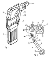
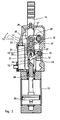
- a first exemplificative embodiment of a clamping device with manual control lever according to the invention is shown in the figures from 1 to 4.
- the clamping device comprises a box-shaped body 10 having a longitudinal axis, onto which a clamping member, in the form of a clamping arm 11, is pivoted at 12 on a side, at one end of the body 10; the clamping arm 11 is operatively connected both to a linear actuator 13 such as a pneumatic cylinder supported by the box-shaped body 10, and to a manual control lever 14 pivoted to the box-shaped body 10 by means of a pivotal axis 15.
- a linear actuator 13 such as a pneumatic cylinder supported by the box-shaped body 10
- a manual control lever 14 pivoted to the box-shaped body 10 by means of a pivotal axis 15.
- the device can alternatively be provided just with the manual control lever 14, whenever the work to be carried out involves only the manual operation of the device by an operator.
- the device may be provided with one or more clamping members rotatingly supported in order to satisfy particular requirements.
- the clamping arm 11 rotates around the pivotal axis 12 to alternately move from a first rearward or open operative position, shown in figure 3 , to a second forward or clamping operative position, shown in figure 4 , in which the arm 11 blocks a metal sheet or a work piece against a shoulder or a support framework, not shown.
- the clamping arm 11 is operatively connected to the manual control lever 14 by a double toggle-lever system comprising a first toggle-lever system 16 and a second toggle-lever system assembly 17 connected to each other by means of an intermediate guide element 18 sliding parallel to the longitudinal axis of the box-shaped body 10.
- the first toggle-lever system 10 connected to the control lever 14 comprises a first link 19 connected to the hinging and pivotal axis 15 of the control lever 14, as well as hinged at 20 to a second link 21, which in turn is hinged at 22 to the sliding guide element 18.
- the second toggle-lever system 17 comprises a connecting link 23, for example of the controlled elastic yielding type, hinged to a fork member 18' of the guide element 18 at a point 24, preferably different and spaced apart from the hinge point 22 of the first toggle-lever system 16, view in the direction of the longitudinal axis of the box-shaped body 10; the connecting link 23 at the same time is hinged at 25 with a second link or crank lever 26 connected to and movable with the clamping arm 11 around the pivot point 12.
- the second toggle-lever system 17 is of a per se known three-point type, which is movable between a backward position of the hinge point 24 and the connecting link 24, which corresponds to a folded condition of the first toggle-lever system 16, see Fig. 3 , and a forward position, which corresponds to an extended condition of the first toggle-lever system 16 as shown in Fig. 4 .
- the guide element 18 and the connecting link 23 of the second toggle-lever system 17, in correspondence with their hinge axis 24, are provided on both sides with guide rolls 27 which are movable along respective sliding guides 28 along the box-shaped body 10, so as to guide the element 18 in a direction parallel to the longitudinal axis of the box-shaped body 10 of the clamping device.
- the first and the second toggle-lever system 16, 17 are constructed and disposed to act in correlation with each other, in such a way that in the forward position of the second connecting link and the clamping arm 11, the pivotal or hinge axes 15,22 and the intermediate hinge axis 20 of the first toggle-lever system 16 are not aligned with one another, that is are laying on two different reference lines A and B forming a small angle ⁇ as explained furthermore, while the second toggle-lever system 17 is in the aforesaid forward condition of irreversibility of its movement, just a little beyond its dead centre, to maintain the clamping arm 11 in the forward condition in which it clamps a work piece, even in the event of accidental thrusts acted upon the clamping arm 11 is tending to open it.
- the linear actuator 13 for example a hydraulic or pneumatic cylinder, whenever contemplated, is provided at rear end of the box-shaped body 10, and is operatively connected to the guide element 18 for the first and the second toggle-lever systems 16,17 by means of a piston rod 29.
- the piston rod 29 has an axis parallel to the longitudinal axis of the box-shaped body 10, and is connected to a movable member of the linear actuator 13, for example a piston 30 of a pneumatic cylinder.
- the guide element 18 is preferably in the form of a bush having a longitudinal slit which opens out on both sides, which is also provided with side guide shoes, not shown, on orthogonal planes to the hinge axes 22, 24 of the connecting links 21, 23; said guide shoes are longitudinally spaced apart from the rolls 27 of the guide element 18, so as to allow the guide element 18 to slide only longitudinally, preventing any rotation or oscillations.
- the connecting link 21 of the first toggle-lever system 16 is preferably housed and pivoted inside the bush-shaped guide element 18, with the crank link 19 of the first toggle-lever system extending into the guide element 18 through one of the longitudinal slits.
- the longitudinal slits of the guide element 18 also offer the first toggle-lever system greater possibilities of rotating, since it is able to partially protrude with respect to the guide element 18, allowing a smaller rotation of the control lever 14 while reducing the overall side dimensions of the device.
- the distance between the hinge axes 15 and 20 is greater than the distance between the hinge axes 20, 22, so that it is possible to rotate the control lever 14 by a smaller angle than the clamping arm 11 of the device.
- the first toggle-lever system 16 in correspondence with its extended condition, is stopped by stop means, such as for example a peg 31 secured to the box-shaped body 10, which preferably comes into contact with the link 19 thereby preventing the links 19 and 21 from assuming an aligned condition of the hinge axes.
- stop means such as for example a peg 31 secured to the box-shaped body 10, which preferably comes into contact with the link 19 thereby preventing the links 19 and 21 from assuming an aligned condition of the hinge axes.
- the angle ⁇ formed between the longitudinal axis or reference line A of the link 19 and B of the link 21 of the first toggle-lever system 16, in correspondence with the clamped condition of the device is smaller than 6°, for example ranging from 2° to 6°, thereby making it possible to at least partially exploit the thrust of the first toggle-lever system 16 in order to generate a high clamping force.
- a second exemplificative embodiment concerns a clamping device, as shown in figure 5 , in which the same reference numbers have been used to indicate similar or equivalent parts.
- the clamping device also comprises a manually operable control lever 14 pivoted to the box-shaped body 10, which is operatively connected to at least one hook-shaped member 35 capable of clamping and/or pressing a work piece against a supporting structure.
- first toggle-lever system 16 comprising a link 19 connected to rotate with the control lever 14 and a connecting link 21 hinged at 20 to the link 19 and at 22 to a guide element 18 sliding along the box-shaped body 10.
- the guide element 18 is in turn hingedly connected to a second toggle-lever system 17 comprising a connecting link 23 hinged at 24 to the guide element 18, and at 25 to the link arm of a crank lever 26; an L-shaped extension 26' of the crank lever 26 constitutes one side of an articulated quadrilateral system which controls the movement of the clamping hook 35 and enables its operative connection with the second toggle-lever system 17.
- the articulated quadrilateral comprises the L-shaped extension 26' of the crank lever 26, pivoted at 36 to the box-shaped body 10; a connecting rod 37 is pivoted at 38 to the box-shaped body 10, while the L-shaped extension 26' and the connecting rod 37 are hinged to the hook member 35 at respective hinging points 39,40 spaced apart from each other.
- the hook member 35 moves from a first raised operative position to a second lowered or clamping operative position, in which the hook member 35 presses and/or retain a work piece against a supporting structure, engaging in a hole provided into the work piece.
- the device can again comprise a linear actuator 13, secured to the box-shaped body 10, having a rod 29 operatively connected to the guide element 18.
- first and the second linkages or toggle-lever systems 16, 17 are constructed and arranged to act in correlation with each other, in such a way that in the forward position of the second toggle-lever system 17, the pivotal axes 15,22 and the intermediate hinging axis 20 of the first toggle-lever system 16 are not aligned with one another, while the second toggle-lever system 17 is in the aforesaid forward condition, that is in a condition of irreversibility of its movement, just a little beyond its dead centre, to retain the clamping arm 11 in the clamped condition.
- a further embodiment of the invention concerns a clamping device for retaining and centring work pieces, as shown in the figures from 6 and 7, in which the same reference numbers have been again used to indicate similar or equivalent parts.
- the centring device comprises a box-shaped body 10 having a longitudinal axis, along which a centring and retaining member, for example a centring pin 45, slide parallely to the axis of the body 10 between a first backward position and a second forward position shown in Fig. 6 .
- a centring and retaining member for example a centring pin 45
- the device also comprises a manually operable control lever 14 pivoted at 15 to the box-shaped body 10 and operatively connected to the centring member 45 by connecting means; the said connecting means in turn comprise a toggle-lever system 16 having a link 19 connected to the pivot pin 15 of the control lever 14, and a second link 21 pivoted at 22 to a guide element 18 longitudinally sliding along the box-shaped body 10, with the links 19 and 21 hinged each other at 20.
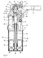
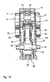
- a further exemplificative embodiment concerns a clamping device as shown in figures 9 and 10 , in which the same reference numbers have been used again to indicate similar or equivalent parts.
- the clamping device again comprises a box-shaped body 10 having a longitudinal axis, and a clamping arm 11 operatively connected both to a linear actuator 13, in this case of the electric type, and to a manually operable control lever 14 pivoted to the same box-shaped body 10 by means of a pivot pin 15.
- the clamping arm 11 is operatively connected to the manual control lever 14 by connecting means comprising a first toggle-lever system 16 and a second toggle-lever system 17 connected to each other by means of an intermediate guide element 18 sliding longitudinally along the box-shaped body 10.
- the first toggle-lever system 16 differs from the one described in the first embodiment of Fig. 1 , in that it comprises a crank member 19A in the form of a fork, connected to the pivot pin 15 of the control lever 14; the fork member 19A preferably comprises a hub 50 coaxially arranged to the pin 15, provided with a first and a second arm 51,52 disposed on the opposing sides of the guide element 18.
- the first arm 51 of the fork member 19A is hinged at 53 to a corresponding first connecting link 54; likewise the second arm 52 of the fork member 19A is hinged at 55, to a second connecting link 56.
- the first and the second connecting links 54,56 are disposed on the opposite sides of the guide element 18, and are hinged to the same guide element 18, at the point 22.
- the second toggle-lever system 17 again comprises a connecting link 23, for example of the controlled elastic yielding type, hinged to a fork member at a point 24, spaced apart from the pivotal point 22 as per case of Fig. 1 ; the connecting link 23 is also hinged at 25 to a link or a crank lever 26 connected to the clamping arm 11.
- the first and the second toggle-lever systems 16,17 are again constructed and arranged to act in correlation with each other, in such a way that in the forward position of the clamping arm 11 and the second toggle-lever system 17, the pivotal axes 15 and 22 and the intermediate hinging axes 53, 55 are not aligned with one another, as in the previous cases 17.
- the linear control actuator 13 comprises a worm screw 57 axially disposed to the box-shaped body 10, which in turn is coupled with a nut screw 58 connected to the guide element 18.
- the worm screw 57 is operatively connected to an electric actuator comprising in this case a first and a second electric motor 59,60, and a torque transmission system.
- each electric motor 59,60 is connected to respective epicyclic reduction gears 61,62, so as to form a first and a second geared motor unit 63,64.
- Each geared motor unit 63,64 is operatively connected to a respective geared torque converter 65,66; the geared torque converters 65,66 are in turn connected to a central gear 67 of the worm screw 57.
Landscapes
- Engineering & Computer Science (AREA)
- Mechanical Engineering (AREA)
- Clamps And Clips (AREA)
- Jigs For Machine Tools (AREA)
- Gripping Jigs, Holding Jigs, And Positioning Jigs (AREA)
- Mechanical Control Devices (AREA)
Claims (11)
- Eine Klemmvorrichtung für das Einspannen von Werkteilen umfasst:- einen kastenförmigen Körper (10) mit einer Längsachse;- eine Klemmvorrichtung (11, 35), beweglich gelagert an dem kastenförmigen Körper (10), zwischen einer ersten oder rückwertigen und einer zweiten oder vorderen operativen Position, zugehörig zu jeweils einem offenen und einem eingespannten Zustand des Apparates;- ein von Hand zu betätigender Kontrollhebel (14), zentral gelagert an dem kastenförmigen Körper (10); und- Verbindungsvorrichtungen für die funktionsfähige Verbindung zwischen der Klemmvorrichtung (11, 35) und dem Kontrollhebel (14), wobei die genannten Verbindungvorrichtungen folgendes umfassen:- einen parallel zur Längsachse des Körpers (10) bewegliches Zwischenführungselement (18);- ein erstes Kipphebelsystem (16) zwischen dem Zwischenführungselement (18) und dem Kontrollhebel (14);- ein zweites Kipphebelsystem (17) zwischen der Klemmvorrichtung (11,35) und dem Zwischenführungselement (18), wobei das erste Kipphebelsystem (16) und das zweite Kipphebelsystem (17) mittels dem Zwischenführungselement (18) miteinander verbunden sind. Das genannte erste Kipphebelsystem umfasst das erste und das zweite Verbindungsteil (19, 21), welche gelenkig miteinander verbunden sind, wobei das erste Verbindungsteil (19) mit einer schwenkbaren und entscheidenden Achse (15) des Kontrollhebels (14), ebenso wie mit dem gelenkigen zweiten Verbindungsteil (21), welches wiederum drehbar an das Gleitführungselement angebracht ist, verbunden ist;- genanntes erstes und zweites Kipphebelsystem (16, 17), die dadurch gekennzeichnet sind, dass sie so konstruiert und angeordnet sind, um in Korrelation auf eine derartige Weise miteinander zu arbeiten, dass die Gelenkachsen (15, 20; 20, 22) der Verbindungsteile (19, 21) des ersten Kipphebelsystems (16), in der vorderen Position der Klemmvorrichtung (11, 35), auf den unterschiedlichen Bezugslinien (A, B) so angeordnet sind, dass sie untereinander einen Winkel (Alpha) formen;- wobei die Klemmvorrichtung darüber hinaus Stoppelemente (31) zum Stoppen des ersten Kipphebelsystems (16) auf der vorderen Position der Klemmelemente (11, 35) der Klemmvorrichtung umfasst und einen geradlinigen Auslöser (13), wobei das Führungselement (18) funktionsgemäß mit dem geradlinigen Auslöser verbunden ist (13).
- Eine Klemmvorrichtung zum Halten und Zentrieren von Werkstücken, das Gerät umfasst:- einen kastenförmigen Körper (10), der eine Längsachse hat;- ein haltendes und zentrierendes Bauteil (45), parallel zu den Achsen des Körpers (10) angeordnet, besagtes zentriertes Bauteil ist beweglich gelagert zwischen einer ersten oder hinteren Position und einer zweiten oder vorderen Position in Bezug auf den kastenförmigen Körper (10) des Gerätes, wobei die Klemmvorrichtung folgendes umfasst:- ein von Hand bedienbarer Kontrollhebel (14), durch den kastenförmigen Körper (10) unterstützt;- ein Führungselement (18) für das zentrierende Bauteil (45); und- eine Verbindungsvorrichtung zwischen dem Führungselement (18) und dem Kontrollhebel (14), genannte Verbindungsvorrichtung umfasst ein Kipphebelsystem (16), das Verbindungsteile (19, 21) beinhaltet, wobei ein Verbindungsteil (19) mit einem Gelenkzapfen (15) des Kontrollhebels (14) verbunden ist und eine zweite Verbindung (21) drehbar an das Führungselement (18) angelagert ist, welches längsgerichtet entlang des kastenförmigen Körpers gleitet (10) mit den Verbindungen (19, 21) gelenkig zueinander verbunden ist, dadurch gekennzeichnet, dass die Gelenkachsen (15, 20; 20, 22) von den Verbindungsteilen (19, 21), in der vorderen Position des zentrierenden Bauteils (45), auf den unterschiedlichen Bezugslinien (A, B) so angeordnet sind, dass sie einen Winkel (Alpha) untereinander formen; und- Stoppelemente (31) zum Stoppen des Kipphebelsystems (16) in der vorderen Position des zentrierenden Bauteils (45) des Gerätes, und in dem die Klemmvorrichtung zusätzlich einen geradlinigen Auslöser (13) umfasst, und das Führungselement (18), dass funktionsfähig mit dem linearen Auslöser (13) verbunden ist.
- Eine Klemmvorrichtung gemäß Anspruch 1,
dadurch gekennzeichnet, dass die Gelenkpunkte (22, 24) des besagten ersten und zweiten Kipphebelsystems (16, 17) für die Verbindung mit dem Führungselement (18) in Längsrichtung des kastenförmigen Körpers (10) auseinander gespreizt sind. - Eine Klemmvorrichtung gemäß Anspruch 1 oder 2,
dadurch gekennzeichnet, dass das Verbindungsteil (19), verbunden mit dem Kontrollhebel (14) des zweiten Kipphebelsystems (16), eine größere Länge als das Verbindungsteil (21), verbunden mit dem Führungselement (18) der Klemmvorrichtung, hat. - Eine Klemmvorrichtung gemäß Anspruch 1,
dadurch gekennzeichnet, dass die Klemmvorrichtung (11) die Form eines drehbar unterstützten Klemmarms hat. - Eine Klemmvorrichtung gemäß Anspruch 1,
dadurch gekennzeichnet, dass die Klemmvorrichtung (11) die Form eines hakenförmigen Teils (35) hat, funktionsfähig verbunden mit dem Führungselement (18) durch genanntes erstes Kontrollhebelsystem (17) und mit einem gelenkigen viereckigen System (37, 39). - Eine Klemmvorrichtung gemäß Anspruch 1 oder 2,
dadurch gekennzeichnet, dass der Winkel (Alpha), zwischen den Bezugslinien (A, B) der Gelenkachsen, von den Verbindungsteilen (19, 21) des zweiten Kipphebelsystems (16), in Übereinstimmung mit seiner verlängerten Lage, kleiner als 6 Grad ist. - Eine Klemmvorrichtung gemäß Anspruch 7,
dadurch gekennzeichnet, dass der Winkel (Alpha) zwischen genannten Bezugslinien (A, B) 2 bis 6 Grad umfasst. - Eine Klemmvorrichtung gemäß Anspruch 1,
dadurch gekennzeichnet, dass genanntes zweites Kipphebelsystem (16) ein Gabelelement (19A) umfasst, verbunden mit dem Kontrollhebel (14), beziehungsweise mit einem Verbindungsteil des Kipphebelsystems (16), genanntes Gabelelement (19A) enthält erste und zweite Arme (51, 52) auf der gegenüber liegenden Seite des Führungselements (18) und jeder Arm (51, 52) des Gabelelements (19A) ist gelenkig durch ein besonderes Verbindungsglied (54, 56) mit dem Führungselement (18) des Gerätes verbunden. - Eine Klemmvorrichtung gemäß Anspruch 1 oder 2,
dadurch gekennzeichnet, dass der lineare Auslöser (13) pneumatisch ist. - Eine Klemmvorrichtung gemäß Anspruch 1 oder 2,
dadurch gekennzeichnet, dass der lineare Auslöser (13) elektrisch ist.
Applications Claiming Priority (2)
| Application Number | Priority Date | Filing Date | Title |
|---|---|---|---|
| IT001914A ITMI20021914A1 (it) | 2002-09-10 | 2002-09-10 | Dispositivo di bloccaggio con leva manuale di comando |
| ITMI20021914 | 2002-09-10 |
Publications (3)
| Publication Number | Publication Date |
|---|---|
| EP1398115A2 EP1398115A2 (de) | 2004-03-17 |
| EP1398115A3 EP1398115A3 (de) | 2008-11-19 |
| EP1398115B1 true EP1398115B1 (de) | 2011-07-13 |
Family
ID=31726548
Family Applications (1)
| Application Number | Title | Priority Date | Filing Date |
|---|---|---|---|
| EP03017165A Expired - Lifetime EP1398115B1 (de) | 2002-09-10 | 2003-07-29 | Spannvorrichtung mit manuellem Kontrolhebel |
Country Status (7)
| Country | Link |
|---|---|
| US (1) | US6814349B2 (de) |
| EP (1) | EP1398115B1 (de) |
| KR (1) | KR100570848B1 (de) |
| BR (1) | BR0303817A (de) |
| CA (1) | CA2436440C (de) |
| IT (1) | ITMI20021914A1 (de) |
| MX (1) | MXPA03008171A (de) |
Cited By (1)
| Publication number | Priority date | Publication date | Assignee | Title |
|---|---|---|---|---|
| CZ310433B6 (cs) * | 2024-03-22 | 2025-06-11 | ŠKODA AUTO a.s | Ručně ovládaná upínka |
Families Citing this family (29)
| Publication number | Priority date | Publication date | Assignee | Title |
|---|---|---|---|---|
| ITMI20021756A1 (it) * | 2002-08-02 | 2004-02-03 | Luciano Migliori | Dispositivo di aggancio per pezzi da lavorare. |
| ITMI20021914A1 (it) * | 2002-09-10 | 2004-03-11 | Univer Spa | Dispositivo di bloccaggio con leva manuale di comando |
| US7815176B2 (en) | 2003-09-11 | 2010-10-19 | Phd, Inc. | Lock mechanism for pin clamp assembly |
| US7516948B2 (en) | 2004-04-02 | 2009-04-14 | Phd, Inc. | Pin clamp accessories |
| US7182326B2 (en) | 2004-04-02 | 2007-02-27 | Phd, Inc. | Pin clamp |
| US7448607B2 (en) | 2004-12-15 | 2008-11-11 | Phd, Inc. | Pin clamp assembly |
| ITMI20050087U1 (it) * | 2005-03-17 | 2006-09-18 | Univer Spa | Dispositivo di bloccaggio per pezzi da lavorare con organo di bloccaggio a forma di gancio |
| ITMI20050436A1 (it) * | 2005-03-17 | 2006-09-18 | Univer Spa | Dispositivo di bloccaggio e centratura per pezzi da lavorare con organo di bloccaggio a forma di gancio |
| DE202005004598U1 (de) * | 2005-03-18 | 2006-07-27 | De-Sta-Co Europe Gmbh | Spannvorrichtung |
| ITMI20051983A1 (it) * | 2005-10-19 | 2007-04-20 | Univer Spa | Dispositivo di frenatura autobloccante per alberi rotanti e relative applicazioni |
| JP4892668B2 (ja) | 2007-02-15 | 2012-03-07 | Smc株式会社 | クランプ装置 |
| ES2707249T3 (es) | 2007-06-19 | 2019-04-03 | Phd Inc | Conjunto de abrazadera de pasador |
| JP2009233695A (ja) * | 2008-03-26 | 2009-10-15 | Fujitsu Ltd | ハンドプレス機 |
| WO2009155261A1 (en) | 2008-06-18 | 2009-12-23 | Phd, Inc. | Strip off pin clamp |
| DE102009048510A1 (de) * | 2009-10-09 | 2011-04-14 | De-Sta-Co Europe Gmbh | Spannvorrichtung |
| DE102011018987A1 (de) * | 2011-04-28 | 2012-10-31 | De-Sta-Co Europe Gmbh | Spannvorrichtung |
| DE202012011156U1 (de) | 2012-06-15 | 2012-12-14 | Tünkers Maschinenbau Gmbh | Unterbodenspanner |
| US10625382B2 (en) * | 2012-08-01 | 2020-04-21 | Delaware Capital Formation, Inc. | Toggle lever clamp |
| DE102014111344A1 (de) * | 2014-08-08 | 2016-02-11 | De-Sta-Co Europe Gmbh | Spannvorrichtung |
| KR101642835B1 (ko) * | 2015-04-10 | 2016-07-26 | (주)한진에프에이 | 수동식 차량시트 고정장치 |
| WO2017016607A1 (en) | 2015-07-30 | 2017-02-02 | Pneumax S.P.A. | Actuating device of the type provided with an actuating element and means for manually operating the actuating element |
| KR101911234B1 (ko) * | 2016-07-28 | 2018-12-31 | 에너지움 주식회사 | 전동 클램핑 장치 |
| US10882148B2 (en) * | 2017-08-01 | 2021-01-05 | Caromation, Inc. | Pivot unit |
| US11759915B2 (en) | 2021-10-03 | 2023-09-19 | Delaware Capital Formation, Inc. | Pneumatic latch clamp |
| CN113909957B (zh) * | 2021-10-12 | 2022-12-13 | 深圳市精雕数控设备有限公司 | 高效的机加工夹具 |
| CN114603382A (zh) * | 2022-04-19 | 2022-06-10 | 东风汽车股份有限公司 | 悬空液压紧固装置 |
| CN116652644B (zh) * | 2023-07-06 | 2023-10-13 | 长沙博大科工股份有限公司 | 一种发动机端盖加工用夹紧夹具 |
| CN117224436B (zh) * | 2023-11-07 | 2024-01-26 | 成都乾坤动物药业股份有限公司 | 一种蕨类植物防晒成分提取方法 |
| CN118848578A (zh) * | 2024-09-24 | 2024-10-29 | 大连亚明汽车部件股份有限公司 | 一种汽车支架加工夹具 |
Family Cites Families (14)
| Publication number | Priority date | Publication date | Assignee | Title |
|---|---|---|---|---|
| US1997428A (en) * | 1933-04-12 | 1935-04-09 | Olson John | Clamping device |
| FR2409819A1 (fr) * | 1977-11-29 | 1979-06-22 | Cecchi Gerard | Dispositif de serrage a commande pneumatique |
| DE8908288U1 (de) | 1989-07-07 | 1989-09-21 | Tünkers, Josef Gerhard, 4030 Ratingen | Kniehebelspannvorrichtung für den Karosseriebau |
| DE3936396C1 (en) * | 1989-11-02 | 1991-04-25 | Josef Gerhard 4030 Ratingen De Tuenkers | Toggle tightening device - has housing containing toggle with piston and cylinder, and right angled two armed lever pivoted at other end |
| DE29516531U1 (de) * | 1995-10-19 | 1995-12-14 | Tünkers Maschinenbau GmbH, 40880 Ratingen | Kniehebelspannvorrichtung |
| DE19616441C1 (de) | 1996-04-25 | 1997-06-26 | Tuenkers Maschinenbau Gmbh | Kniehebelspannvorrichtung für den Karosseriebau |
| DE19645778C2 (de) * | 1996-11-07 | 1999-07-08 | Sta Co Mettallerzeugnisse Gmbh | Kniehebel-Spannvorrichtung |
| DE29701730U1 (de) * | 1997-02-01 | 1997-04-30 | Tünkers Maschinenbau GmbH, 40880 Ratingen | Kniehebelspannvorrichtung, insbesondere zur Verwendung in Vorrichtungen und Schweißmaschinen des Karosseriebaus der Kfz-Industrie |
| DE29920639U1 (de) * | 1999-11-24 | 2000-03-30 | Tünkers Maschinenbau GmbH, 40880 Ratingen | Kniehebelspannvorrichtung, insbesondere zur Verwendung im Karosseriebau der Kfz-Industrie |
| DE20100701U1 (de) | 2001-01-16 | 2001-03-22 | Tünkers Maschinenbau GmbH, 40880 Ratingen | Druckmittelbetätigbare kombinierte Zentrier- und Spannvorrichtung, insbesondere zur Verwendung im Karosseriebau der Kfz-Industrie |
| DE60201371T2 (de) * | 2001-04-19 | 2005-11-17 | S.P.A. Univer | Kniehebelspannvorrichtung |
| US6595507B2 (en) * | 2001-08-22 | 2003-07-22 | Delaware Capital Formation, Inc. | Hold down toggle clamp |
| DE10159874C1 (de) * | 2001-12-06 | 2003-02-27 | Tuenkers Maschinenbau Gmbh | Werkzeug |
| ITMI20021914A1 (it) * | 2002-09-10 | 2004-03-11 | Univer Spa | Dispositivo di bloccaggio con leva manuale di comando |
-
2002
- 2002-09-10 IT IT001914A patent/ITMI20021914A1/it unknown
-
2003
- 2003-07-29 EP EP03017165A patent/EP1398115B1/de not_active Expired - Lifetime
- 2003-08-05 KR KR1020030053948A patent/KR100570848B1/ko not_active Expired - Fee Related
- 2003-08-05 CA CA002436440A patent/CA2436440C/en not_active Expired - Fee Related
- 2003-09-09 US US10/657,240 patent/US6814349B2/en not_active Expired - Fee Related
- 2003-09-09 BR BR0303817-3A patent/BR0303817A/pt not_active IP Right Cessation
- 2003-09-10 MX MXPA03008171A patent/MXPA03008171A/es active IP Right Grant
Cited By (1)
| Publication number | Priority date | Publication date | Assignee | Title |
|---|---|---|---|---|
| CZ310433B6 (cs) * | 2024-03-22 | 2025-06-11 | ŠKODA AUTO a.s | Ručně ovládaná upínka |
Also Published As
| Publication number | Publication date |
|---|---|
| US20040046299A1 (en) | 2004-03-11 |
| ITMI20021914A1 (it) | 2004-03-11 |
| CA2436440A1 (en) | 2004-03-10 |
| BR0303817A (pt) | 2004-09-08 |
| MXPA03008171A (es) | 2004-11-29 |
| US6814349B2 (en) | 2004-11-09 |
| KR20040023499A (ko) | 2004-03-18 |
| EP1398115A2 (de) | 2004-03-17 |
| KR100570848B1 (ko) | 2006-04-12 |
| EP1398115A3 (de) | 2008-11-19 |
| CA2436440C (en) | 2008-05-13 |
Similar Documents
| Publication | Publication Date | Title |
|---|---|---|
| US6814349B2 (en) | Clamping device with manual control lever | |
| US6976671B2 (en) | Toggle-lever clamping device for clamping work pieces with self-compensation | |
| CN1041389C (zh) | 具有轴向夹紧作用的锁紧钳 | |
| US8245560B2 (en) | Crimping pliers | |
| EP1352806B1 (de) | Lenksäule | |
| KR20050009192A (ko) | 측면 클램핑 부재를 가진 컴팩트 클램핑 장치 | |
| CA2381473C (en) | Toggle lever clamping device | |
| US6350079B1 (en) | Quick coupler assembly | |
| US20040021260A1 (en) | Coupling device for work pieces | |
| US20040195747A1 (en) | Compact electric clamping device | |
| US20070158890A1 (en) | Drive device for actuating a linearly movable operative member | |
| US6666478B2 (en) | Steering column | |
| US5711183A (en) | Device in a bending unit | |
| KR101433414B1 (ko) | 기어 변속 시스템 | |
| EP1649968A2 (de) | Einrichtung zum Greifen eines Werkstückes für roboterartige Handhabungssyteme | |
| EP1661659A1 (de) | Schwenkanordnung | |
| EP1566488B1 (de) | Baggerauslegergelenkanordnung | |
| GB2435258A (en) | Control apparatus for a material handling vehicle | |
| WO2006086962A1 (de) | Scharnier für eine fahrzeugklappe | |
| WO2025193939A1 (en) | Locking mechanism | |
| JPS6111147B2 (de) | ||
| JP3242245B2 (ja) | 油圧式建設機械の安全装置 | |
| AU5579694A (en) | A tool | |
| JP2014084027A (ja) | 動力舵取装置 | |
| WO2007050514A2 (en) | Force multiplying structure for ram actuated devices |
Legal Events
| Date | Code | Title | Description |
|---|---|---|---|
| PUAI | Public reference made under article 153(3) epc to a published international application that has entered the european phase |
Free format text: ORIGINAL CODE: 0009012 |
|
| AK | Designated contracting states |
Kind code of ref document: A2 Designated state(s): AT BE BG CH CY CZ DE DK EE ES FI FR GB GR HU IE IT LI LU MC NL PT RO SE SI SK TR |
|
| AX | Request for extension of the european patent |
Extension state: AL LT LV MK |
|
| PUAL | Search report despatched |
Free format text: ORIGINAL CODE: 0009013 |
|
| AK | Designated contracting states |
Kind code of ref document: A3 Designated state(s): AT BE BG CH CY CZ DE DK EE ES FI FR GB GR HU IE IT LI LU MC NL PT RO SE SI SK TR |
|
| AX | Request for extension of the european patent |
Extension state: AL LT LV MK |
|
| 17P | Request for examination filed |
Effective date: 20090513 |
|
| AKX | Designation fees paid |
Designated state(s): CZ DE FR GB IT SK |
|
| TPAC | Observations by third parties |
Free format text: ORIGINAL CODE: EPIDOSNTIPA |
|
| 17Q | First examination report despatched |
Effective date: 20091123 |
|
| RTI1 | Title (correction) |
Free format text: CLAMPING DEVICE WITH MANUAL CONTROL LEVER |
|
| GRAP | Despatch of communication of intention to grant a patent |
Free format text: ORIGINAL CODE: EPIDOSNIGR1 |
|
| GRAS | Grant fee paid |
Free format text: ORIGINAL CODE: EPIDOSNIGR3 |
|
| GRAA | (expected) grant |
Free format text: ORIGINAL CODE: 0009210 |
|
| AK | Designated contracting states |
Kind code of ref document: B1 Designated state(s): CZ DE FR GB IT SK |
|
| REG | Reference to a national code |
Ref country code: GB Ref legal event code: FG4D |
|
| REG | Reference to a national code |
Ref country code: DE Ref legal event code: R096 Ref document number: 60337651 Country of ref document: DE Effective date: 20110901 |
|
| PG25 | Lapsed in a contracting state [announced via postgrant information from national office to epo] |
Ref country code: SK Free format text: LAPSE BECAUSE OF FAILURE TO SUBMIT A TRANSLATION OF THE DESCRIPTION OR TO PAY THE FEE WITHIN THE PRESCRIBED TIME-LIMIT Effective date: 20110713 Ref country code: CZ Free format text: LAPSE BECAUSE OF FAILURE TO SUBMIT A TRANSLATION OF THE DESCRIPTION OR TO PAY THE FEE WITHIN THE PRESCRIBED TIME-LIMIT Effective date: 20110713 |
|
| PLBE | No opposition filed within time limit |
Free format text: ORIGINAL CODE: 0009261 |
|
| STAA | Information on the status of an ep patent application or granted ep patent |
Free format text: STATUS: NO OPPOSITION FILED WITHIN TIME LIMIT |
|
| PG25 | Lapsed in a contracting state [announced via postgrant information from national office to epo] |
Ref country code: IT Free format text: LAPSE BECAUSE OF FAILURE TO SUBMIT A TRANSLATION OF THE DESCRIPTION OR TO PAY THE FEE WITHIN THE PRESCRIBED TIME-LIMIT Effective date: 20110713 |
|
| 26N | No opposition filed |
Effective date: 20120416 |
|
| REG | Reference to a national code |
Ref country code: DE Ref legal event code: R097 Ref document number: 60337651 Country of ref document: DE Effective date: 20120416 |
|
| REG | Reference to a national code |
Ref country code: FR Ref legal event code: PLFP Year of fee payment: 14 |
|
| PGFP | Annual fee paid to national office [announced via postgrant information from national office to epo] |
Ref country code: DE Payment date: 20160722 Year of fee payment: 14 Ref country code: GB Payment date: 20160715 Year of fee payment: 14 |
|
| PGFP | Annual fee paid to national office [announced via postgrant information from national office to epo] |
Ref country code: FR Payment date: 20160715 Year of fee payment: 14 |
|
| REG | Reference to a national code |
Ref country code: DE Ref legal event code: R119 Ref document number: 60337651 Country of ref document: DE |
|
| GBPC | Gb: european patent ceased through non-payment of renewal fee |
Effective date: 20170729 |
|
| REG | Reference to a national code |
Ref country code: FR Ref legal event code: ST Effective date: 20180330 |
|
| PG25 | Lapsed in a contracting state [announced via postgrant information from national office to epo] |
Ref country code: DE Free format text: LAPSE BECAUSE OF NON-PAYMENT OF DUE FEES Effective date: 20180201 Ref country code: GB Free format text: LAPSE BECAUSE OF NON-PAYMENT OF DUE FEES Effective date: 20170729 |
|
| PG25 | Lapsed in a contracting state [announced via postgrant information from national office to epo] |
Ref country code: FR Free format text: LAPSE BECAUSE OF NON-PAYMENT OF DUE FEES Effective date: 20170731 |