EP1396649B1 - Magnetic bearing device with vibration restraining function, magnetic bearing device with vibration estimating function, and pump device with the magnetic bearing devices mounted thereto - Google Patents
Magnetic bearing device with vibration restraining function, magnetic bearing device with vibration estimating function, and pump device with the magnetic bearing devices mounted thereto Download PDFInfo
- Publication number
- EP1396649B1 EP1396649B1 EP03255465A EP03255465A EP1396649B1 EP 1396649 B1 EP1396649 B1 EP 1396649B1 EP 03255465 A EP03255465 A EP 03255465A EP 03255465 A EP03255465 A EP 03255465A EP 1396649 B1 EP1396649 B1 EP 1396649B1
- Authority
- EP
- European Patent Office
- Prior art keywords
- magnetic bearing
- rotor
- vibration
- acceleration
- displacement
- Prior art date
- Legal status (The legal status is an assumption and is not a legal conclusion. Google has not performed a legal analysis and makes no representation as to the accuracy of the status listed.)
- Expired - Fee Related
Links
Images


Classifications
-
- F—MECHANICAL ENGINEERING; LIGHTING; HEATING; WEAPONS; BLASTING
- F16—ENGINEERING ELEMENTS AND UNITS; GENERAL MEASURES FOR PRODUCING AND MAINTAINING EFFECTIVE FUNCTIONING OF MACHINES OR INSTALLATIONS; THERMAL INSULATION IN GENERAL
- F16C—SHAFTS; FLEXIBLE SHAFTS; ELEMENTS OR CRANKSHAFT MECHANISMS; ROTARY BODIES OTHER THAN GEARING ELEMENTS; BEARINGS
- F16C32/00—Bearings not otherwise provided for
- F16C32/04—Bearings not otherwise provided for using magnetic or electric supporting means
- F16C32/0406—Magnetic bearings
- F16C32/044—Active magnetic bearings
- F16C32/0444—Details of devices to control the actuation of the electromagnets
-
- F—MECHANICAL ENGINEERING; LIGHTING; HEATING; WEAPONS; BLASTING
- F16—ENGINEERING ELEMENTS AND UNITS; GENERAL MEASURES FOR PRODUCING AND MAINTAINING EFFECTIVE FUNCTIONING OF MACHINES OR INSTALLATIONS; THERMAL INSULATION IN GENERAL
- F16C—SHAFTS; FLEXIBLE SHAFTS; ELEMENTS OR CRANKSHAFT MECHANISMS; ROTARY BODIES OTHER THAN GEARING ELEMENTS; BEARINGS
- F16C2360/00—Engines or pumps
- F16C2360/44—Centrifugal pumps
- F16C2360/45—Turbo-molecular pumps
Definitions
- the present invention relates to a magnetic bearing device with a vibration restraining function, a magnetic bearing device with a vibration estimating function, and a pump device with the magnetic bearing devices mounted thereto. More specifically, the invention relates to a magnetic bearing device with a vibration restraining function, a magnetic bearing device with a vibration estimating function, and a pump device with the magnetic bearing devices mounted thereto, in which it is possible to realize a reduction in vibration in the apparatus system as a whole inclusive of the equipment associated with the vacuum pump without newly providing a vibration sensor.
- Such semiconductors are manufactured, for example, by doping a semiconductor substrate of a very high purity with impurities to impart electrical properties thereto, or by stacking together semiconductor substrates with minute circuit patterns formed thereon.
- a high vacuum chamber In order to avoid the influences of dust, etc. in the air.
- This chamber is generally evacuated by a vacuum pump.
- a turbo-molecular pump which is a kind of vacuum pump, is widely used since it entails little residual gas and is easy of maintenance.
- a semiconductor manufacturing process includes a number of steps in which various process gases are caused to act on a semiconductor substrate, and the turbo-molecular pump is used not only to evacuate the chamber but also to discharge these process gases from the chamber.
- a turbo-molecular pump is used to create a high vacuum state in the chamber of the apparatus in order to prevent refraction, etc. of an electron beam due to the presence of dust or the like.
- Such a turbo-molecular pump is composed of a turbo-molecular pump main body for sucking and discharging gas from the chamber of a semiconductor manufacturing apparatus, an electron microscope, or the like, and a control device for controlling the turbo-molecular pump main body.
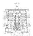
- Fig. 10 is a longitudinal sectional view of a turbo-molecular pump main body
- Fig. 11 is a schematic diagram showing an apparatus system as a whole in which the turbo-molecular pump main body is used to evacuate a chamber.
- a turbo-molecular pump main body 100 includes an outer cylinder 127, on top of which there is formed an intake hole 101.
- a rotor 103 having in its periphery a plurality of rotary blades 102a, 102b, 102c, ... serving as turbine blades for sucking and discharging gas and formed radially in a number of stages.
- a rotor shaft 113 At the center of the rotor 103, there is mounted a rotor shaft 113, which is supported in a levitating state and controlled in position, for example, by a so-called 5-axis control magnetic bearing.
- Upper radial electromagnets 104 consist of four electromagnets arranged in pairs in X- and Y-axis directions, perpendicular to each other, and opposed to each other with the rotor shaft 113 therebetween. It is to be assumed that the X- and Y-axes are in a plane perpendicular to the axis of the rotor shaft 113 when the rotor shaft 113 is at a control target position of the magnetic bearing. Further, there is provided an upper radial sensor 107 consisting of four coils wound around cores and arranged in close proximity to and in correspondence with the upper radial electromagnets 104. The upper radial sensor 107 detects radial displacement of the rotor 103, transmitting a detection signal to a control device 200 shown in Fig. 11 .
- the control device 200 is equipped with magnetic bearing feedback control means composed of a compensator 201, an amplifier 202, etc.
- excitation of the upper radial electromagnets 104 is controlled by the output of the amplifier 202 supplied through the compensator 201 having a PID adjusting function, on the basis of a displacement signal detected by the upper radial sensor 107, thus performing adjustment of the radial position of the upper portion of the rotor shaft 113.
- the rotor shaft 113 is formed of a high-magnetic-permeability material (e.g., iron) and is adapted to be attracted by the magnetic force of the upper radial electromagnets 104. Such adjustment is conducted independently in the X-axis direction and the Y-axis direction.
- a high-magnetic-permeability material e.g., iron
- lower radial electromagnets 105 and a lower radial sensor 108 are arranged in the same way as the upper radial electromagnets 104 and the upper radial sensor 107.
- the radial position of the lower portion of the rotor shaft 113 is adjusted by the magnetic bearing feedback control means in the control device 200.
- axial electromagnets 106A and 106B are arranged respectively on the upper and lower sides of a metal disc 111 provided in the lower portion of the rotor shaft 113.
- the metal disc 111 is formed of a high-magnetic-permeability material, such as iron.
- an axial sensor 109 To detect axial displacement of the rotor 103, there is provided an axial sensor 109, which transmits an axial displacement signal to the control device 200.
- the axial electromagnets 106A and 106B are excitation-controlled by the output of the amplifier 202 supplied through the compensator 201, which has a PID adjusting function, of the control device 200, on the basis of the axial displacement signal.
- the axial electromagnet 106A magnetically attracts the metal disc 111 upwardly, and the axial electromagnet 106B magnetically attracts the metal disc 111 downwardly.
- the magnetic force the axial electromagnets 106A and 106B exert on the metal disc 111 is appropriately controlled by the magnetic bearing feedback control means, magnetically levitating the rotor shaft 113 in the axial direction and retaining it in the space in a non-contact state.
- a motor 121 is equipped with a plurality of magnetic poles consisting of permanent magnets arranged circumferentially on the rotor side so as to surround the rotor shaft 113.
- a torque component for rotating the rotor shaft 113 is imparted to these permanent magnet magnetic poles from the electromagnets on the stator side of the motor 121, thereby rotating the rotor 103.
- an RPM sensor and a motor temperature sensor are mounted to the motor 121, and the rotation of the rotor shaft 113 is controlled in the control device 200 in response to detection signals from the RPM sensor and the motor temperature sensor.
- a plurality of stationary blades 123a, 123b, 123c, ... are arranged so as to be spaced apart from the rotary blades 102a, 102b, 102c, ... by small gaps.
- the rotary blades 102a, 102b, 102c, ... are inclined by a predetermined angle with respect to a plane perpendicular to the axis of the rotor shaft 113.
- the stationary blades 123 are also inclined by a predetermined angle with respect to a plane perpendicular to the axis of the rotor shaft 113, and extend toward the inner side of the outer cylinder 127 to be arranged alternately with the rotary blades 102.
- the stationary blades 123 are supported at one end by being inserted into gaps between a plurality of stationary blade spacers 125a, 125b, 125c, ... stacked together in stages.
- the stationaryblade spacers 125 are ring-shapedmembers, which are formed of a metal, such as aluminum, iron, stainless steel, or copper, or an alloy containing such metal as a component.
- the outer cylinder 127 In the outer periphery of the stationary blade spacers 125, the outer cylinder 127 is secured in position with a small gap therebetween. At the bottom of the outer cylinder 127, there is arranged a base portion 129, and a threaded spacer 131 is arranged between the lowermost one of the stationary blade spacers 125 and the base portion 129.
- a discharge outlet 133 In the portion of the base portion 129 below the threaded spacer 131, there is formed a discharge outlet 133. Connected to the discharge outlet 133 is a dry-sealed vacuum pump passage (not shown), and the discharge outlet 133 is connected to a dry-sealed vacuum pump (not shown) through this dry-sealed vacuum pump passage.
- the threaded spacer 131 is a cylindrical member formed of a metal, such as aluminum, copper, stainless steel, or iron, or an alloy containing such metal as a component, and has a plurality of spiral thread grooves 131a in its inner peripheral surface.
- the spiral direction of the thread grooves 131a is determined such that when the molecules of the exhaust gas move in the rotating direction of the rotor 103, these molecules are transferred toward the discharge outlet 133.
- a cylindrical portion 102d Connected to the lowermost one of the rotary blades 102a, 102b, 102c, ... of the rotor 103 is a cylindrical portion 102d, which extends vertically downwards.
- the outer peripheral surface of this cylindrical portion 102d sticks out toward the inner peripheral surface of the threaded spacer 131, and is in close proximity to the inner peripheral surface of the threaded spacer 131 with a predetermined gap therebetween.
- the base portion 129 is a disc-like member constituting the base of the turbo-molecular pump main body 100, and is generally formed of a metal, such as iron, aluminum, or stainless steel.
- the base portion 129 physically retains the turbo-molecular pump main body 100, and also functions as a heat conduction passage.
- the base portion 129 is preferably formed of a metal that is rigid and of high heat conductivity, such as iron, aluminum, or copper.
- a connector 160 to which is connected a signal line between the turbo-molecular pump main body 100 and the control device 200.
- the exhaust gas sucked in through the intake hole 101 passes between the rotary blades 102 and the stationary blades 123, and is transferred to the base portion 129.
- the exhaust gas transferred to the base portion 129 is sent to the discharge outlet 133 while being guided by the thread grooves 131a of the threaded spacer 131.
- the electrical portion is covered with a stator column 122, and the interior of this electrical portion is maintained at a predetermined pressure with a purge gas.
- the base portion 129 is equipped with piping (not shown), and the purge gas is introduced through the piping.
- the purge gas introduced is passed through the gap between a protective bearing 120 and the rotor shaft 113, the gap between the rotor and stator of the motor 121, and the gap between the stator column 122 and the rotary blades 102 before it is transmitted to the discharge outlet 133.
- the turbo-molecular pump main body 100 requires identification of the model and control based on individually adjusted specific parameters (e.g., characteristics corresponding to the model). To store the control parameters, the turbo-molecular pump main body 100 contains an electronic circuit portion 141.
- the electronic circuit portion 141 is composed of a semiconductor memory, such as EEP-ROM, electronic parts, such as semiconductor devices for access to the semiconductor memory, a substrate 143 for mounting these components thereto, etc.
- This electronic circuit portion 141 is accommodated under an RPM sensor (not shown) near the center of the base portion 129 constituting the lower portion of the turbo-molecular pump main body 100, and is closed by a hermetic bottom cover 145.
- turbo-molecular pump main body 100 which is used for the chamber 300 of a semiconductor manufacturing apparatus, an electron microscope, or the like.
- the turbo-molecular pump main body 100 is suspended from the chamber 300 through the intermediation of a pump damper 301.
- the pump damper 301 shown in Fig. 11 is equipped with a bellows 302, around the outer periphery of which a rubber member 306 is wrapped. Between the turbo-molecular pump main body 100 and the chamber 300, the vibration due to the rotation of the rotor 103 is absorbed. One end of the bellows 302 is fastened to the chamber 300 through the intermediation of a flange (not shown), and the other end thereof is fastened to the intake hole 101 of the turbo-molecular pump main body 100 through the intermediation of a flange 303.
- the chamber 300 is supported by a frame 402 arranged on a floor 400, and a device damper 401 is provided between the chamber 300 and the frame 402.
- this device damper 401 also absorbs vibration between the frame 402 and the chamber 300.
- vibration generated from the floor 400 is similarly absorbed by the device damper 401, and is not easily transmitted to the chamber 300.
- a plurality of pump dampers 301 and a plurality of device dampers 401 are provided in series between the chamber 300 and the turbo-molecular pump main body 100 and between the chamber 300 and the frame 402, respectively, thereby achieving an improvement in terms of vibration damping effect for the chamber 300.
- a plurality of pump dampers 301 and a plurality of device dampers 401 are provided in series between the chamber 300 and the turbo-molecular pump main body 100 and between the chamber 300 and the frame 402, respectively, thereby achieving an improvement in terms of vibration damping effect for the chamber 300.
- turbo-molecular pump main body 100 As a result of the recent increase in the volume of the chamber 300 of a semiconductor manufacturing apparatus or the like, there is a demand for an increase in evacuation speed for the turbo-molecular pump main body 100. To cope with this, the turbo-molecular pump main body 100 and the pump damper 301 have been increased in size.
- the dry-sealed vacuum pump (not shown) connected to the turbo-molecular pump main body 100 generates vibration, which, although small, is transmitted to the turbo-molecular pump main body 100, etc. through the dry-sealed vacuum pump passage, causing the chamber 300 to vibrate. Further, vibration generated by this dry-sealed vacuum pump and other semiconductor manufacturing apparatus, etc., vibration generated by people walking, etc. are also transmitted to the floor 400, and may cause the chamber 300 to vibrate.
- Such vibration of the chamber 300 cannot be avoided by reducing the vibration of the turbo-molecular pump main body 100 itself, and there is a demand for a reduction in vibration in the apparatus system as a whole including not only the turbo-molecular pump main body 100 but also the chamber 300.
- JP 2002-147454 A discloses a rotary machine equipped with a magnetic bearing device capable of reducing vibration in a place spaced apart from the magnetic bearing to some degree.
- a vibration detecting sensor is arranged on the flange 303 of the pump damper 301, a flange (not shown) on the chamber 300 side or the like, and, on the basis of a detection signal detected by this vibration detecting sensor, reverse-phase vibration is imparted to the rotor 103, thereby canceling the vibration of the apparatus system as a whole.
- this vibration detecting sensor is arranged on the pump damper 301 side, the chamber 300 side, etc. , it is necessary to secure previously an installation space around the pump damper 301, the chamber 300, etc., and, to establish communication between the vibration detecting sensor and the control device 200, it is necessary to newly provide a signal line between the pump damper 301, the chamber 300, etc.
- the present invention has been made in view of the above-mentioned conventional problem, and therefore an object of the present invention is to provide a magnetic bearing device with a vibration restraining function, a magnetic bearing device with a vibration estimating function, and a pump device with the magnetic bearing devices mounted thereto, in which it is possible to realize a reduction in vibration in the apparatus system as a whole inclusive of the equipment associated with the vacuum pump.
- the invention relates to a magnetic bearing device with a vibration restraining function, including: a rotor; electromagnets applying a levitating force to the rotor; a stator portion to which the electromagnets are secured; displacement detecting means for detecting radial and/or axial relative displacement of the rotor with respect to the stator portion; a magnetic bearing control compensator that calculates an adjusting amount of the levitating force on the basis of the relative displacement detected by the displacement detecting means; electromagnet control means for adjusting the levitating force in accordance with a calculation result of the adjusting amount of the levitating force as obtained by the magnetic bearing control compensator; vibration detecting means for detecting a predetermined physical amount of a stationary apparatus portion whose position relative to the stator portion is fixed; and adding means for adding an output of the vibration detecting means, with a polarity of the output reversed, to a transfer signal of magnetic bearing feedback control means formed at least by the displacement
- the vibration detecting means detects the predetermined physical amount of the stationary apparatus portion and/or the stator portion, and outputs it to the addition means. Further, the addition means reverses the polarity of the signal output from the vibration detecting means and adds it to the output of the magnetic bearing feedback control means.
- the magnetic bearing device can be endowed with a vibration restraining function.
- the Laplace transformation of the displacement of the rotor refers to Y(s) in Equation 5.
- the present invention relates to the magnetic bearing device with a vibration restraining function, including unbalance force detecting means for detecting or estimating an unbalance force acting on the rotor, characterized in that the acceleration is a transformation result obtained through transformation of an addition result into time domain, the addition result being obtained by adding to the first multiplication result a second multiplication result obtained by multiplying a Laplace transformation of a variation in the unbalance force acting on the rotor detected or estimated by the unbalance force detecting means by a reciprocal of a mass of the rotor.
- the magnetic bearing device can be endowed with a vibration restraining function for restraining vibration generated in the stationary apparatus portion and/or the stator portion due to the unbalance force acting on the rotor.
- the present invention relates to the magnetic bearing device with a vibration restraining function, characterized in that the predetermined transfer function is expressed by a transfer function peculiar to the magnetic bearing feedback control means, the transfer function being a relationship between the relative displacement of the rotor and a force acting between the electromagnets and the rotor due to the relative displacement, and by a mass of the rotor.
- the predetermined transfer function is a function defined by the mass of the rotor and the transfer function peculiar to the magnetic bearing feedback control means.
- the transfer function peculiar to the magnetic bearing feedback control means is a function determined at the designing stage for the magnetic bearing.
- the transfer functionpeculiar to the magnetic bearing feedback control means refers to F(s) in Equations 4 and 5.
- the present invention relates to a magnetic bearing device with a vibration restraining function, including: a rotor; electromagnets applying a levitating force to'the rotor; a stator portion to which the electromagnets are secured; displacement detecting means for detecting radial and/or axial relative displacement of the rotor with respect to the stator portion; a magnetic bearing control compensator that calculates an adjusting amount of the levitating force on the basis of the relative displacement detected by the displacement detecting means; electromagnet control means for adjusting the levitating force in correspondence with a calculation result of the adjusting amount of the levitating force obtained by the magnetic bearing control compensator; vibration detecting means for detecting a predetermined physical amount of a stationary apparatus portion whose position relative to the stator portion is fixed; and adding means for adding an output of the vibration detecting means, with a polarity of the output reversed, to a transfer signal of magnetic bearing feedback control means formed at least by the displacement detecting means, the magnetic bearing control compensator, and
- the acceleration is the subtraction result obtained by subtracting the result obtained by performing second-order differentiation on the relative displacement of the rotor detected by the displacement detecting means, from the third multiplication result obtained as the result of the multiplication of the addition result obtained by the addition means and the reciprocal of the mass of the rotor.
- the calculation result of the adjusting amount of the levitating force obtained by the magnetic bearing control compensator or the addition result obtained through addition by the addition means, which is already known, is used, so that it is possible to accurately calculate the acceleration, etc. of the stationary apparatus portion and/or the stator portion by using an inexpensive computing device.
- the present invention relates to the magnetic bearing device with a vibration restraining function, including magnetic flux detecting means for detecting a variation in a magnetic flux generated between the electromagnets and the rotor, characterized in that a multiplication result which is obtained by using a value proportional to the variation in the magnetic flux detected by the magnetic flux detecting means instead of the calculation result of the adjusting amount of the levitating force obtained by the magnetic bearing control compensator, is used as the third multiplication result.
- the adjusting amount of the levitating force to be applied to the rotor from the electromagnets there is used a value proportional to the variation in the magnetic flux detected by the magnetic flux detecting means.
- the present invention relates to the magnetic bearing device with a vibration restraining function, including: an induction motor for rotating the rotor; and motor control means for controlling an energization state of the induction motor, characterized in that, when the predetermined physical amount is to be detected by the vibration detecting means, the motor control means brings the induction motor into a non-energized state.
- the present invention relates to the magnetic bearing device with a vibration restraining function, including a rotation frequency follow-up type notch filter adapted to follow up a rotation frequency of the rotor to eliminate a frequency component of the rotation frequency, characterized in that at least one of the acceleration, the displacement, the speed, and the addition acceleration is a result obtained by passing the subtraction result through the rotation frequency follow-up type notch filter.
- the unbalance force acting on the rotor is approximated to a sine wave whose frequency is the rotation frequency of the rotor.
- a rotation frequency following type notch filter following the rotation frequency of the rotor to eliminate the frequency component, it is possible to detect the acceleration, etc. of the stationary apparatus portion and/or the stator portion without taking into account the result obtained around the rotation frequency of the rotor.
- the rotation frequency refers to the number of rotation per second.
- the present invention relates to the magnetic bearing device with a vibration restraining function, including a low-pass filter through which at least one of the acceleration, the displacement, the speed, and the addition acceleration is passed.
- the present invention relates to the magnetic bearing device with a vibration restraining function, including vibration restraint control compensating means for performing at least one of gain adjustment and/or phase compensation, PID control, and other control compensation on the output of the vibration detecting means .
- the vibration restraint control compensating means may consist of a compensator effecting gain adjustment and/or phase compensation on the output signal of the vibration detecting means, or a PID control compensator, or other type of control compensators, such as an optimum control compensator, an H ⁇ control compensator, or a sliding mode control compensator. Further, it is also possible to adopt a combination of at least two of these compensators.
- the above arrangement makes it possible to effectively restrain vibration without dispersing vibration of the stationary apparatus portion and/or the stator portion.
- the present invention relates to a magnetic bearing device with a vibration estimating function, including: a rotor; electromagnets applying a levitating force to the rotor; a stator portion to which the electromagnets are secured; displacement detecting means for detecting radial and/or axial relative displacement of the rotor with respect to the stator portion; a magnetic bearing control compensator that calculates an adjusting amount of the levitating force based on the displacement detected by the displacement detecting means; electromagnet control means for adjusting the levitating force in correspondence with a calculation result of the adjusting amount of the levitating force obtained by the magnetic bearing control compensator; vibration detecting means for detecting a predetermined physical amount of a stationary apparatus portion whose relative position with respect to the stator portion is fixed, the magnetic bearing device being characterized in that: the predetermined physical amount is at least one of an acceleration of the stationary apparatus portion and/or the stator portion, a displacement, a speed, and an addition acceleration, each of the displacement, the speed, and the
- the present invention relates to a magnetic bearing device with a vibration estimating function, including: a rotor; electromagnets applying a levitating force to the rotor; a stator portion to which the electromagnets are secured; displacement detecting means for detecting radial and/or axial relative displacement of the rotor with respect to the stator portion; magnetic bearing control compensator that calculates an adjusting amount of the levitating force based on the displacement detected by the displacement detecting means; electromagnet control means for adjusting the levitating force in correspondence with a calculation result of the adjusting amount of the levitating force obtained by the magnetic bearing control compensator; vibration detecting means for detecting a predetermined physical amount of a stationary apparatus portion whose relative position with respect to the stator portion is fixed, the magnetic bearing device being characterized in that: the predetermined physical amount is at least one of an acceleration of the stationary apparatus portion and/or the stator portion, a displacement, a speed, and an addition acceleration, each of the displacement, the speed, and the addition acceleration
- the present invention relates to the magnetic bearing device with a vibration estimating function, including magnetic flux detecting means for detecting a variation in a magnetic flux generated between the electromagnets and the rotor, characterized in that a multiplication result which is obtained by using a value proportional to the variation in the magnetic flux detected by the magnetic flux detecting means instead of the calculation result of the adjusting amount of the levitating force obtained by the magnetic bearing control compensator, is used as the third multiplication result.
- the present invention relates to a pump device with one of a vibration restraining function and a vibration estimating function which includes a vacuum pump with a magnetic bearing device mounted thereto, characterized in that the vacuum pump is installed in associated equipment and adapted to suck a predetermined gas from the associated equipment.
- the vacuum pump is installed in the associated equipment, and has mounted thereto the magnetic bearing device with one of a vibration restraining function and a vibration estimating function.
- the above arrangement makes it possible to realize a reduction in or estimation of vibration in the apparatus system as a whole inclusive of the equipment associated with the vacuum pump without newly providing a vibration sensor.
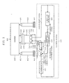
- FIG. 1 is a schematic diagram showing an apparatus system as a whole according to the first embodiment of the present invention.
- the components that are the same as those of Fig. 11 are indicated by the same symbols, and a description of such components will be omitted.
- a control device 500 shown in Fig. 1 , includes, in addition to the conventional control device 200 equipped with magnetic bearing feedback control means, a vibration detector 503 serving as the vibration detecting means, a vibration restraint control compensator 504 serving as the vibration restraint control compensating means, and an adder 505 serving as the adding means.
- Input to the vibration detector 503 are displacement signals output from rotor position sensors 107, 108, and 109 of the turbo-molecular pump main body 100.
- a first multiplication result obtained through multiplication of Laplace transformation of displacement of the rotor 103 and a predetermined transfer function and a second multiplication result obtained through multiplication of Laplace transformation of a variation in an unbalance force acting on the rotor 103 and the reciprocal of the mass of the rotor 103, are added together, and the addition result is transformed into time domain, the transformation result being output as an acceleration signal of a stationary apparatus portion 600.
- the requisite parameters for the calculation of a transfer function are previously determined (or previously measured), and are stored in a storage device (not shown) or the like.
- the output signal of the vibration detector 503 is output to the vibration restraint control compensator 504 as the acceleration of the stationary apparatus portion 600.
- the stationary apparatus portion 600 refers to the chamber 300 and the portion of the turbo-molecular pump main body 100 other than the rotor 103.
- the vibration restraint control compensator 504 multiplies the acceleration signal output from the vibration detector 503 by an amplification factor with a predetermined frequency characteristic to adjust gain, and effects phase compensation to prevent divergence or oscillation of the stationary apparatus portion 600.
- Input to the adder 505 are a position control force command signal that is an output signal of the compensator 201 and an acceleration adjustment signal that is an output signal of the vibration restraint control compensator 504.
- the adder 505 is adapted to reverse the polarity (positive/negative) of the acceleration adjustment signal and to add it to the position control force command signal.
- a control force command value which is an addition result obtained by the adder 505 is output to the amplifier 202 serving as the electromagnet control means .
- a levitating support force is applied to the rotor 103 from the amplifier 202 through the electromagnets 104, 105, 106A, and 106B.
- the electromagnets 104, 105, 106A, and 106B receive the reaction force of the levitating support force. Since the reaction force includes a force restraining vibration of the stationary apparatus portion 600, vibration of the stationary apparatus portion 600 is restrained by this force.
- the apparatus system shown in Fig. 1 has a pump fixing portion 304 provided between the turbo-molecular pump main body 100 and the chamber 300.
- This pump fixing portion 304 is equipped with a cylindrical fixing column 305, and is adapted to fix the turbo-molecular pump main body 100 to the chamber 300.
- one end of the fixing column 305 is fastened to the chamber 300 through the intermediation of a flange (not shown), and the other end thereof is fastened to the intake hole 101 of the turbo-molecular pump main body 100 through the intermediation of a flange 303.
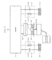
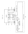
- Fig. 2 is a block diagram showing the apparatus system as a whole.
- the components that are the same as those of Fig. 1 are indicated by the same symbols and a description of such components will be omitted.
- Fig. 2 shows an apparatus damper 401, whose function can be modeled by an elastic member 401a having a spring constant of k s and a viscous drag 401b having a viscosity coefficient of c s .
- the rotor 103 of the turbo-molecular pump main body 100 is supported in a levitating state by the electromagnets 104, 105, 106A, and 106B.
- the rigidity in this levitation support can be radially expressed by a transfer function F r (s) whose input is the Laplace transformation of radial displacement of the rotor 103 with respect to the stationary apparatus portion 600 and whose output is the Laplace transformation of variation in the force applied from the electromagnets 104 and 105 to the rotor 103.
- the rigidity in this levitation support can be expressed by a transfer function F a (s) whose input is the Laplace transformation of axial displacement of the rotor 103 with respect to the stationary apparatus portion 600 and whose output is the Laplace transformation of variation in the sum of the forces applied from the electromagnets 106A and 106B to the rotor 103.
- transfer functions F r (s) and F a (s) may be regarded as transfer functions peculiar to the magnetic bearing feedback control means composed of the compensator 201, amplifier 202, etc. of the control device 500.
- turbo-molecular pump main body 100 is secured to the chamber 300, so that the stationary apparatus portion 600, that is, the chamber 300 and the portion of the turbo-molecular pump main body 100 other than the rotor 103, may be regarded as an integral unit.
- the motion model between the floor 400, the stationary apparatus portion 600, and the rotor 103 can be expressed as the model as shown in Fig. 3 in both the radial and axial directions.
- displacement x b (t) represents absolute displacement of the floor 400.
- displacement x s (t) indicates absolute displacement of the stationary apparatus portion 600
- displacement x r (t) indicates absolute displacement of the rotor 103 .
- mass m s indicates the mass of the stationary apparatus portion 600
- mass m r indicates the mass of the rotor 103.
- disturbance force b p (t) indicates the disturbance force acting on the stationary apparatus portion 600.
- the disturbance force b p (t) may, for example, be vibration, etc. transmitted from the dry-sealed vacuum pump connected to the turbo-molecular pump main body 100.
- unbalance force u b (t) is the unbalanced force generated due to positional deviation between the configuration central axis and inertia central axis of the rotor 103.
- Equation 4 the f(y(t)) can be expressed as a linear equation of y(t), so that through Laplace transformation of Equation 3, with the initial value being 0, Equation 4 is obtained.
- Equation 4 expresses the acceleration of the stationary apparatus portion 600 in the Laplace domain. Through transformation of both sides of the Equation 4 into time domain, it is possible to obtain the acceleration of the stationary apparatus portion 600.
- the relative displacement y(t) can be detected by the rotor position sensors 107, 108, and 109.
- the unbalance force u b (t) it can be estimated, by forming an observer, from the control force with which the magnetic bearing supports the rotor 103 in a levitating state and displacement of the rotor 103 as detected by the rotor position sensors 107, 108, and 109, as disclosed, for example, in " Construction of Magnetic Bearing Control System Endowed with Unbalance Compensating Function” (by Mizuno and Higuchi, Transactions of Society of Instrument and Control Engineers, 20, 12, p1095 ), and " Resilient Rotor Feed Forward Type Unbalance Force Compensating Control” (International Journal of Japan Society of Mechanical Engineers, Volume C, 56, 528 (1990), pp. 2056-2064 .
- the unbalance force acting on the rotor 103 is estimated by an observer, and the unbalance force acting on the rotor 103 is compensated for through feed forward control, thereby restraining vibration of the rotor 103.
- the acceleration of the stationary apparatus portion 600 is obtained through calculation based on transformation result of Equation 4 or 5 (described below) into time domain, and this acceleration is restrained, which means that the present invention differs from the above examples in control object and control method.
- the rotor 103 is intentionally caused to vibrate, and, by utilizing the force acting on the stationary apparatus portion 600 due to the vibration, the vibration of the stationary apparatus portion 600 is restrained.
- the acceleration of the stationary apparatus portion 600 does not depend on the condition on the stationary apparatus 600 side, and can be obtained from a parameter existing on the turbo-molecular pump main body 100 side and displacement signals detected by the rotor position sensors 107, 108, and 109.
- the vibration detector 503 of the control device 500 obtains the acceleration of the stationary apparatus portion 600 through calculation of the result of transformation of both sides of Equation 4 into time domain, and outputs a signal representing this acceleration.
- This signal is input to the vibration restraint control compensator 504, where the gain when addition to the output of the compensator 201 is effected is adjusted. Further, in the vibration restraint control compensator 504, the control device 500, the vibration restraint control compensator 504, and the turbo-molecular pump main body 100 constitutes the feedback control system, so that phase compensation or the like is effected on the acceleration signal so that the stationary apparatus portion 600 may not diverge or oscillate.
- the acceleration adjustment signal output from the vibration restraint control compensator 504 is sent to the adder 505, where its polarity (positive/negative) is reversed so as to restrain the vibration of the stationary apparatus portion 600, and is added to the position control force command signal, which is the output of the compensator 201.
- the addition result i.e., the control force command value
- the amplifier 202 which excites the electromagnets 104, 105, 106A, and 106B on the basis of the control force command value from the adder 505 to support the rotor 103 in a levitating state.
- the electromagnets 104, 105, 106A, and 106B receive reaction force of the levitating support force applied to the rotor 103. Since this reaction force contains a force restraining vibration of the stationary apparatus portion 600, vibration of the stationary apparatus portion 600 is restrained by this force.
- turbo-molecular pump main body 100 and the control device 500 are capable of restraining vibration of the apparatus system as a whole.
- This restraint of vibration can be achieved by utilizing solely the displacement signals of the rotor position sensors 107, 108, and 109 and the parameter on the turbo-molecular pump main body 100 side, without newly installing a vibration detection sensor or the like.
- vibration detector 503 obtains the acceleration of the stationary apparatus portion 600 through calculation of the transformation result of Equation 4 into time domain, this should not be construed restrictively.
- the vibration restraint control compensator 504 effects gain adjustment and phase compensation on the output signal of the vibration detector 503, this should not be construed restrictively. It is also possible to adopt a PID control compensator, an optimum control compensator, an H ⁇ control compensator, a sliding mode control compensator or a compensator of some other type, or a combination of at least two of these compensators. Further, when the displacement of the rotor 103, which is the control object of the compensator 201, and the acceleration of the stationary apparatus portion 600, which is the control object of the vibration restraint control compensator 504, do not diverge or oscillate, there is no need to provide the vibration restraint control compensator 504.
- the adder 505 adds the acceleration adjustment signal output from the vibration restraint control compensator 504 to the output signal of the compensator 201 after reversing the polarity (positive/negative) of the acceleration adjustment signal, and outputs the control force command value, which is the addition result thereof, to the amplifier 202, this should not be construed restrictively.
- the adder 505 may add the acceleration adjustment signal to any signal as long as it is a transfer signal in the feedback control loop of the control device 500.
- the adder 505 may be connected between the rotor position sensors 107, 108, and 109 and the compensator 201, and adds the acceleration adjustment signal output from the vibration restraint control compensator 504 to the displacement signals from the rotor position sensors 107, 108, and 109 after reversing the polarity (positive/negative) of the acceleration adjustment signal, and may output the addition result to the compensator 201.
- the vibration restraint control compensator 504 performs control compensation according to the transfer signal in the feedback control loop in which the acceleration adjustment signal is added by the adder 505 after being reversed in polarity (positive/negative).
- the compensator 201 is generally endowed with a function by which it performs other control compensations such as signal gain adjustment, signal phase compensation, PID control compensation, optimum control compensation, H ⁇ control compensation, sliding mode control compensation, etc.
- the function which has been conducted by the vibration restraint control compensator 504 can be easily incorporated into the compensator 201.
- this embodiment is applicable not only to a 5-axis control magnetic bearing, but also to 3-axis and 1-axis control magnetic bearings.
- 1-axis control only an electromagnet having the control function exists for one axis, so that, when the stationary apparatus portion 600 vibrates, the direction in which a force restraining the vibration can be applied is one direction allowing control by the electromagnet.
- vibration of the stationary apparatus portion 600 is restrained by calculating the acceleration of the stationary apparatus portion 600
- this may also be achieved by calculating a physical amount corresponding to the result obtained by differentiating or integrating the acceleration the requisite number of times, such as the addition acceleration, speed, position of the stationary apparatus portion 600.
- transfer functions F r (s) and F a (s) are calculated when obtaining the force applied to the rotor 103 from the electromagnets 104 and 105 or the electromagnets 106A and 106B
- a control force command value, etc. output from the adder 505 are used instead of calculating the transfer functions F r (s) and F a (s).
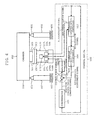
- Fig. 4 is a schematic diagram showing an apparatus system as a whole according to the second embodiment of the present invention.
- the components that are the same as those of Fig. 1 are indicated by the same symbols, and a description of such components will be omitted.
- the control device 550 shown in Fig. 4 is equipped, instead of the vibration detector 503 of the first embodiment, with a vibration-detector/motor-controller 553 serving as the vibration detecting means and the motor control means.
- a control force command value which is the output of the adder 505, is input to this vibration-detector/motor-controller 553.
- this control force command value is used when obtaining the acceleration of the stationary apparatus portion 600.
- an induction motor 171 is used instead of the motor 121 of the first embodiment having a permanent magnet. Output to this induction motor 171 from the vibration-detector/motor-controller 553 is a non-energization signal. While the acceleration of the stationary apparatus portion 600 is being calculated in the vibration-detector/motor-controller 553, the induction motor 171 is in a non-energized (free-run) state.
- vibration-detector/motor-controller 553 is equipped with a rotation frequency follow-up type notch filter 806 (described in detail below) for reducing the error due to the unbalance force u b (t) acting on the rotor 103.
- a magnetic flux detection signal indicating variation in the magnetic flux generated between the rotor 103 and the electromagnets 104 and 105 or the electromagnets 106A and 106B may be input to the vibration-detector/motor-controller 553 of this embodiment. Then, it is also possible to obtain the acceleration of the stationary apparatus portion 600 on the basis of the variation in this magnetic flux.
- the turbo-molecular pump main body 150 is equipped with a magnetic flux detector 181 for detecting variation in the magnetic flux generated between the rotor 103 and the electromagnets 104 and 105 or the electromagnets 106A and 106B, and the detection result is output to the vibration-detector/motor-controller 553.
- Fig. 2 which is the same block diagram showing the apparatus system as a whole as used for the description of the first embodiment, will be referred to.
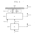
- Fig. 6 shows a motion model formed based on this block diagram.
- the functions f r and f a are defined as the relationship between the relative displacement y(t) and the force applied to the rotor 103 by the electromagnets 104 and 105 or the electromagnets 106A and 106B, no definition is made of these functions f r and f a in this embodiment.
- the magnetic bearing levitating force adjusting amount f mb (t) itself is defined as the force applied to the rotor 103 by the electromagnets 104 and 105 or the electromagnets 106A and 106B.
- the motion model of this embodiment takes into consideration a motor force f mt (t) as the force applied to the rotor 103 by the induction motor 171.
- the unbalance force u b (t) is approximated to a sine wave the angular velocity of which is equal to the rotation angular velocity ⁇ of the rotor 103 (hereinafter referred to as unbalance force u b ( ⁇ t)).
- this unbalance force u b ( ⁇ t) is an unbalance force generated due to positional deviation between the configuration central axis and inertia central axis of the rotor 103, so that the unbalance force u b ( ⁇ t) can be thus approximated to a sine wave the angular velocity of which is ⁇ .
- the functions f r and f a are defined as the relationship between the relative displacement y(t) and the force applied to the rotor 103 by the electromagnets 104 and 105 or the electromagnets 106A and 106B.
- the functions f r and f a are transformed into a Laplace domain, and the acceleration of the stationary apparatus portion 600 in the Laplace domain is obtained from the transfer functions F r (s), F a (s), etc. Further, this is transformed into time domain, thereby obtaining the acceleration of the stationary apparatus portion 600.
- the requisite parameters for the calculation of the transfer functions F r (s) and F a (s) must be determined or measured beforehand, and these must be stored in the vibration detector 503. Further, the calculation of the transfer functions F r (s) and F a (s) is complicated in itself, so that a high-speed computing unit is required.
- the magnetic bearing levitating force adjusting amount f mb (t) itself is defined, and a control force command value output from the adder 505 is used as the magnetic bearing levitating force adjusting amount f mb (t).
- the control force command value which is a known value, is used, so that even an inexpensive computing unit suffices.
- the error between the actual magnetic bearing levitating force adjusting amount f mb (t) and this control force command value can constitute a problem.
- this problem can be eliminated by arranging the electromagnets so as to be opposed to each other with the rotor 103 therebetween, in a plane perpendicular to the rotor shaft 113, and by using, as the control device 550, a high gain magnetic flux feedback controller in which the variation in the magnetic flux generated from the electromagnets 104 and 105 or the electromagnets 106A and 106B quickly follows up the control force command value output from the adder 505.
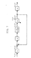
- Fig. 7 is a block diagram showing this high gain magnetic flux feedback controller.
- F r (s) indicates the Laplace transformation of the variation in the control force command value f r (t).
- V m (s) indicates the Laplace transformation of the variation in the magnetic flux command value v m (t)
- I m (s) indicates the Laplace transformation of the variation in the electromagnet current value I m (t)
- ⁇ m (s) indicates the Laplace transformation of the variation in the magnetic flux ⁇ mb (t) of the electromagnets.
- F mb (s) indicates the Laplace transformation of the variation in the control force f mb (t) of the electromagnets
- X(s) indicates the Laplace transformation of the variation in the gap between the electromagnets and the rotor.
- R indicates the resistance of the coils of the electromagnets
- L indicates the inductance of the electromagnets.
- the magnetic flux command value v m (t) and the control magnetic flux ⁇ m (t) generated from the electromagnets 104 and 105 or the electromagnets 106A and 106B are brought into one to one correspondence with each other. Further, the variation in the magnetic flux ⁇ m (t) is maintained in a proportional relationship with the levitating force adjusting amount f mb (t). Assuming that the proportional gain K 1 is the reciprocal of this proportional constant K 4 , the control force command value f r (t) is brought into one to one correspondence with the levitation force adjusting amount f mb (t).
- the motor force f mt (t) is taken into consideration in calculating the acceleration of the stationary apparatus portion 600.
- an induction motor 171 is used instead of the motor 121 using permanent electromagnets.
- the induction motor 171 is kept in a non-energized state, whereby the influence of the motor force f mt (t) is nullified.
- the motor 121 using permanent electromagnets the influence of the magnetic flux due to the permanent electromagnets cannot be nullified, so that it is necessary to always take the influence of the motor force f m t(t) into consideration.
- the period in which the induction motor 171 is kept in the non-energized state be determined as follows.
- the period of time in which image taking is performed by the electron microscope that is, the period of time in which the restraint of vibration is most desired, is several seconds or so.
- approximately several tens of seconds to one minute suffices as the period of time in which the induction motor 171 is kept in the non-energized state.
- the unbalance force u b ( ⁇ t) can be estimated from the magnetic bearing levitating force adjusting amount and information on rotor displacement output from the rotor position sensors.
- the unbalance force u b ( ⁇ t) is approximated to a sine wave the angular velocity of which is the rotation angular velocity ⁇ of the rotor 103.
- the calculation error involved is restricted to the frequency of the rotation angular velocity ⁇ of the rotor 103, and, in the other frequency bands, the acceleration of the stationary apparatus portion 600 can be calculated accurately.
- the run-out of the rotor 103 due to this unbalance force u b ( ⁇ t) is also restricted to the frequency of the rotation angular velocity ⁇ .
- the run-out x d of the rotor 103 with respect to the stationary apparatus portion 600 can be expressed by Equation 9 through Fourier expansion.
- R r ( ⁇ t) is the rotation frequency component (generated by the unbalance force u b ) of the run-out of the rotor 103
- ⁇ is the rotation angular velocity of the rotor 103
- t is time
- E r is the frequency component other than the rotation frequency of the run-out of the rotor 103
- R s ( ⁇ t) is the rotation frequency component of the rotor 103 of the displacement of the stationary apparatus portion 600
- a r is the amplitude of R r ( ⁇ t) ; ⁇
- the run-out x d of the rotor 103 with respect to the stationary apparatus portion 600 is detected by the rotor position sensors 107, 108, and 109. Further, the rotation angular velocity ⁇ of the rotor 103 is detected by the RPM sensor or the like provided on the motor 121, etc.
- the following calculation is performed on the detection signal x d of the rotor 103 detected by the rotor position sensors 107, 108, and 109.
- Equations 10 and 11 are obtained.
- Equations 12 and 13 are obtained.
- Equations 12 and 13 By passing Equations 12 and 13 through a low-pass filter whose cutoff frequency is low, the AC component is removed, whereby Equations 14 and 15 are obtained.
- Equations 14 and 15 are obtained.
- a r 1 / 2 ⁇ A r cos ⁇ r - A s cos ⁇ s
- b r 1 / 2 ⁇ A r sin ⁇ r - A s sin ⁇ s
- Equations 14 and 15 are respectively multiplied by sin( ⁇ t) and cos( ⁇ t) and added together, and then amplified twofold, whereby, as shown in Equation 16, there is obtained the rotation frequency component R r ( ⁇ t)-R s ( ⁇ t) of the run-out of the rotor 103 with respect to the stationary apparatus portion 600.
- Equation 17 a result signal x o is obtained as shown in Equation 17.
- Fig. 8 is a block diagram showing the principle of the above-described rotation frequency follow-up type notch filter 806.
- an input 701 corresponds to the detection signal x d in Equations 10 and 11. Further, a sine wave 702 and a cosine wave 703 correspond to sin( ⁇ t) and cos( ⁇ t) multiplied in Equations 10 and 11. Low-pass filters 704 and 705 correspond to the low-pass filters through which Equations 12 and 13 are passed. As a result, the output 706 of Fig. 8 corresponds to the rotation frequency component R r ( ⁇ t)-R s ( ⁇ t) of the displacement of the rotor 103 with respect to the stationary apparatus portion 600 calculated in Equation 16. By subtracting this output 706 from the input 701 (not shown), the result signal x o of Equation 17 is obtained.
- Equation 8 for the calculation of the acceleration of the stationary apparatus portion 600 is simplified as shown in Equation 18.
- Equation 19 is not a proper formula (That is, the degree of the Laplace operator s of the numerator is larger than the degree of the Laplace operator s of the denomiator), and, as is apparent from Equation 18, this calculation requires a secondary differentiator for performing second-order differentiation on the relative displacement y(t).
- the gain increases as the frequency increases, so that if an attempt is made to restrain vibration of the stationary apparatus portion 600 through feedback input of this calculation result to the vibration restraint control compensator may result in the stability of the feedback control system being impaired. Further, generally speaking, noise is often generated in a high frequency band, and tends to be amplified by this differentiator.
- Equation 19 it is desirable for Equation 19 to be a strictly proper equation (that is, an equation in which the degree of the Laplace operator s of the numerator is smaller than the degree of the Laplace operator s of the denominator).
- Equation 20 by passing the calculation result of Equation 19 through the secondary low-pass filter, Equation 20 is obtained.
- ⁇ and ⁇ c are predetermined constants.
- Equation 21 is a strictly proper formula with respect to all the terms.
- Fig. 9 is a block diagram showing the above method of calculating the acceleration of the stationary apparatus portion 600.
- an input 801 corresponds to the Laplace transformation Y(s) of the relative displacement y(t) in Equation 21.
- an input 802 corresponds to the Laplace transformation F mb (s) of the magnetic bearing levitating force adjusting amount f mb (t) in Equation 21.
- a low-pass filter 803 corresponds to the coefficient of the third and fourth terms of the right side of Equation 21, and a low-pass filter 804 corresponds to' the coefficient of the first and second terms of the right side of the equation.
- an intermediate output 805 corresponds to the Laplace transformation s 2 X s (s) of the acceleration of the stationary apparatus portion 600 of Equation 21.
- the vibration restraining operation of this embodiment is the same as that of the first embodiment except that control is performed on the induction motor 171 by non-energization signal from the vibration-detector/motor-controller 553.
- the vibration-detector/motor-controller 553 brings the induction motor 171 into a non-energized state on the basis of this signal.
- the calculation of the stationary apparatus portion 600 is performed in the vibration-detector/motor-controller 553, and an acceleration signal is output to the vibration restraint control compensator 504 (The operations from this onward are the same as those in the first embodiment).
- the vibration-detector/motor-controller 553 When a signal to the effect that the image taking or the like by the electron microscope has been completed is input to the vibration-detector/motor-controller 553 from the chamber 300 side (not shown), the vibration-detector/motor-controller 553 energizes the induction motor 171 on the basis of this signal.
- the calculation of the acceleration of the stationary apparatus portion 600 is performed by using a magnetic bearing control force command value, etc., so that it is possible to perform calculation with high accuracy using an inexpensive computing unit.
- the acceleration of the stationary apparatus portion 600 is obtained on the basis of a strictly proper formula like Equation 21, it is possible to achieve an improvement in terms of the stability of the vibration restraint feedback control system and a reduction in noise.
- the acceleration of the stationary apparatus portion 600 is obtained from Equation 21, etc., this should not be construed restrictively. It is also possible, as in the first embodiment, to calculate a physical amount corresponding to the result obtained by differentiating or integrating the acceleration the requisite number of times, such as the addition acceleration, speed, position of the stationary apparatus portion 600.
- turbo-molecular pump main body 150 is fixed to the chamber 300, this should not be construed restrictively.
- the stationary apparatus potion 600 it is most desirable for the stationary apparatus potion 600 to consist of a perfectly rigid body since that will make it possible to obtain the effect as described above.
- the chamber 300, etc. do not always consist of perfect rigid bodies.
- the acceleration, etc. of the stationary apparatus portion 600 corresponding to each of the rotor position sensors 107, 108, and 109 are obtained on the basis of displacement signals from these sensors to thereby control the electromagnets 104, 105, 106A, and 106B, this should not be construed restrictively.
- the motion of the rotor 103 is a complicated combination of motion of a translation component and motion of a rotation component. And, as has been conventionally conducted, the motion of the rotor 103 can be separated into a translation component and a rotation component from the detection results obtained by the upper radial sensor 107, the lower radial sensor 108, etc.
- the acceleration, etc. of the stationary apparatus portion 600 in correspondence with each of the translation component and the rotation component of the rotor 103, it is possible to obtain the translation component and the rotation component of the acceleration, etc. of the stationary apparatus portion 600.
- the following calculations are performed.
- the translation component of the displacement of the rotor 103 is substituted into the relative displacement y(t) of Equation 8.
- the rotation component of the displacement of the rotor 103 is substituted into the relative displacement y(t) of Equation 8
- the moment of inertia of the rotor 103 around its rotation center axis is substituted into the mass m r of Equation 8.
- the control force command value, etc. for the upper radial electromagnets 104 and the lower radial electromagnets 105 are obtained again, thereby controlling the electromagnets 104 and 105.
- the magnetic bearing device is equipped with vibration detecting means, adding means, and vibration restraint control means, whereby it is possible to realize a reduction in vibration in the apparatus system as a whole inclusive of the equipment associated with the vacuum pump without newly providing a vibration sensor.
- the magnetic bearing device is equipped with vibration detecting means, it is possible to realize vibration detection in the apparatus system as a whole inclusive of the equipment associated with the vacuum pump without newly providing a vibration sensor.
Landscapes
- Engineering & Computer Science (AREA)
- General Engineering & Computer Science (AREA)
- Mechanical Engineering (AREA)
- Physics & Mathematics (AREA)
- Electromagnetism (AREA)
- Magnetic Bearings And Hydrostatic Bearings (AREA)
- Non-Positive Displacement Air Blowers (AREA)
- Connection Of Motors, Electrical Generators, Mechanical Devices, And The Like (AREA)
Applications Claiming Priority (2)
| Application Number | Priority Date | Filing Date | Title |
|---|---|---|---|
| JP2002257538 | 2002-09-03 | ||
| JP2002257538 | 2002-09-03 |
Publications (3)
| Publication Number | Publication Date |
|---|---|
| EP1396649A2 EP1396649A2 (en) | 2004-03-10 |
| EP1396649A3 EP1396649A3 (en) | 2005-06-08 |
| EP1396649B1 true EP1396649B1 (en) | 2008-04-02 |
Family
ID=31712280
Family Applications (1)
| Application Number | Title | Priority Date | Filing Date |
|---|---|---|---|
| EP03255465A Expired - Fee Related EP1396649B1 (en) | 2002-09-03 | 2003-09-02 | Magnetic bearing device with vibration restraining function, magnetic bearing device with vibration estimating function, and pump device with the magnetic bearing devices mounted thereto |
Country Status (5)
| Country | Link |
|---|---|
| US (2) | US6806606B2 (ja) |
| EP (1) | EP1396649B1 (ja) |
| JP (1) | JP4287213B2 (ja) |
| KR (1) | KR20040020852A (ja) |
| DE (1) | DE60320072T2 (ja) |
Families Citing this family (27)
| Publication number | Priority date | Publication date | Assignee | Title |
|---|---|---|---|---|
| FR2829200B1 (fr) * | 2001-09-06 | 2004-12-31 | Mecanique Magnetique Sa | Dispositif et procede de compensation automatique de perturbations synchrones |
| US20030155882A1 (en) * | 2002-02-19 | 2003-08-21 | Nikon Corporation | Anti-gravity mount with air and magnets |
| JP4287213B2 (ja) * | 2002-09-03 | 2009-07-01 | エドワーズ株式会社 | 振動抑制機能を有する磁気軸受装置、振動推定機能を有する磁気軸受装置及び該磁気軸受装置を搭載したポンプ装置 |
| JP2005273802A (ja) * | 2004-03-25 | 2005-10-06 | Boc Edwards Kk | 磁気軸受装置及び該磁気軸受装置を搭載したターボ分子ポンプ |
| KR101185265B1 (ko) * | 2004-10-15 | 2012-09-21 | 에드워즈 가부시키가이샤 | 댐퍼 및 진공 펌프 |
| JP4962851B2 (ja) * | 2006-03-06 | 2012-06-27 | 株式会社島津製作所 | 真空ポンプ |
| DE102006034478A1 (de) | 2006-07-26 | 2008-01-31 | Oerlikon Leybold Vacuum Gmbh | Verfahren zur Ermittlung einer Aussage über einen Zustand einer Turbomolekularpumpe sowie eine Turbomolekularpumpe |
| JP4914165B2 (ja) * | 2006-10-06 | 2012-04-11 | エドワーズ株式会社 | 制振装置及び制振方法 |
| JP2008229806A (ja) * | 2007-03-23 | 2008-10-02 | Jtekt Corp | 磁気軸受装置 |
| US8279401B2 (en) * | 2008-04-25 | 2012-10-02 | Asml Netherlands B.V. | Position control system, a lithographic apparatus and a method for controlling a position of a movable object |
| US8128649B2 (en) | 2008-12-16 | 2012-03-06 | Slater Charles R | Spring scissor blade |
| JP5763885B2 (ja) * | 2010-01-29 | 2015-08-12 | 株式会社東芝 | 磁気浮上装置 |
| JP5966651B2 (ja) * | 2012-06-19 | 2016-08-10 | 株式会社ジェイテクト | 主軸装置 |
| DE102013219196A1 (de) * | 2013-09-24 | 2015-03-26 | Siemens Aktiengesellschaft | Verfahren zum Kompensieren einer niederfrequenten Stör-Kraft eines Rotors mit aktiven Magnetlagern, aktives Magnetlager mit Kompensations-Regel-Kreis zur Durchführung des Kompensierens und Verwendung des Magnetlagers |
| JP6015701B2 (ja) * | 2014-03-27 | 2016-10-26 | Jfeスチール株式会社 | 鋼板の制振制御方法及び制振制御装置 |
| US9816965B2 (en) | 2014-11-14 | 2017-11-14 | General Electric Company | Method to detect vibration nodes between a sensor and an actuator in a rotatable component |
| WO2017027382A1 (en) | 2015-08-10 | 2017-02-16 | Exxonmobil Upstream Research Company | Device and method for magnetically controlled dry gas seal |
| US10132412B2 (en) | 2016-08-05 | 2018-11-20 | Exxonmobil Upstream Research Company | Device and method for controlling rotating equipment seal without buffer support equipment |
| JP6864447B2 (ja) * | 2016-09-06 | 2021-04-28 | キヤノン株式会社 | リソグラフィ装置、および物品の製造方法 |
| JP7148230B2 (ja) * | 2017-08-31 | 2022-10-05 | エドワーズ株式会社 | 真空ポンプ及び制御装置 |
| CN111193454B (zh) * | 2020-01-16 | 2023-05-09 | 江苏大学 | 开关磁阻轮毂电机减振及脉动抑制复合控制系统构造方法 |
| CN111836013B (zh) * | 2020-07-09 | 2022-04-12 | 河南中电投华新电力工程有限公司 | 一种基于vr的火电厂检修平台 |
| EP3992594A1 (en) * | 2020-10-29 | 2022-05-04 | Rolls-Royce Deutschland Ltd & Co KG | System and method for detecting vibrations in rotating machinery |
| CN113623239A (zh) * | 2021-09-16 | 2021-11-09 | 北京航空航天大学宁波创新研究院 | 一种不平衡磁拉力控制方法、装置、系统、设备和介质 |
| CN114235143B (zh) * | 2021-12-16 | 2023-09-22 | 常州大学 | 一种磁悬浮多跨转子不对中振动的自适应检测系统 |
| CN114371622B (zh) * | 2022-01-07 | 2024-04-12 | 北京航空航天大学 | 基于多谐波逆Park变换的磁悬浮转子谐波振动力抑制方法 |
| CN115514280A (zh) * | 2022-10-20 | 2022-12-23 | 核工业西南物理研究院 | 一种磁悬浮电机加入低通滤波模块后控制启机振荡的方法 |
Family Cites Families (16)
| Publication number | Priority date | Publication date | Assignee | Title |
|---|---|---|---|---|
| FR2561738B1 (fr) * | 1984-03-26 | 1986-08-22 | Europ Propulsion | Procede et dispositif de reduction des vibrations des machines tournantes equipees d'une suspension magnetique active |
| US4795927A (en) * | 1986-05-02 | 1989-01-03 | Mitsubishi Jukogyo Kabushiki Kaisha | Control system for a magnetic type bearing |
| US4999534A (en) * | 1990-01-19 | 1991-03-12 | Contraves Goerz Corporation | Active vibration reduction in apparatus with cross-coupling between control axes |
| JPH0720359B2 (ja) * | 1990-03-16 | 1995-03-06 | 株式会社荏原製作所 | 回転体のアンバランス修正装置 |
| EP0527846B1 (de) * | 1990-05-08 | 1994-08-31 | Teldix GmbH | Vibrationsisolation eines magnetisch gelagerten körpers |
| US5202824A (en) * | 1990-06-21 | 1993-04-13 | Mechanical Technology Incorporated | Rotating force generator for magnetic bearings |
| JPH0676808B2 (ja) * | 1991-07-02 | 1994-09-28 | 株式会社荏原製作所 | 磁気軸受装置 |
| JP3182197B2 (ja) * | 1992-03-16 | 2001-07-03 | 株式会社荏原製作所 | 磁気軸受装置 |
| JP3296074B2 (ja) * | 1994-03-18 | 2002-06-24 | 株式会社日立製作所 | 高速回転体およびそれに用いる磁気軸受の制御装置 |
| US5736801A (en) * | 1995-08-18 | 1998-04-07 | Ebara Corporation | Filter circuit and control circuit for controlling a rotor |
| US6074180A (en) * | 1996-05-03 | 2000-06-13 | Medquest Products, Inc. | Hybrid magnetically suspended and rotated centrifugal pumping apparatus and method |
| US6394769B1 (en) * | 1996-05-03 | 2002-05-28 | Medquest Products, Inc. | Pump having a magnetically suspended rotor with one active control axis |
| JP2002147454A (ja) * | 2000-11-15 | 2002-05-22 | Seiko Instruments Inc | 磁気軸受装置を備える回転機械 |
| FR2829200B1 (fr) * | 2001-09-06 | 2004-12-31 | Mecanique Magnetique Sa | Dispositif et procede de compensation automatique de perturbations synchrones |
| JP2003166554A (ja) * | 2001-11-28 | 2003-06-13 | Mitsubishi Heavy Ind Ltd | 回転装置の駆動軸 |
| JP4287213B2 (ja) * | 2002-09-03 | 2009-07-01 | エドワーズ株式会社 | 振動抑制機能を有する磁気軸受装置、振動推定機能を有する磁気軸受装置及び該磁気軸受装置を搭載したポンプ装置 |
-
2003
- 2003-08-18 JP JP2003207729A patent/JP4287213B2/ja not_active Expired - Fee Related
- 2003-08-29 US US10/651,518 patent/US6806606B2/en not_active Ceased
- 2003-09-02 DE DE60320072T patent/DE60320072T2/de not_active Expired - Fee Related
- 2003-09-02 EP EP03255465A patent/EP1396649B1/en not_active Expired - Fee Related
- 2003-09-03 KR KR1020030061419A patent/KR20040020852A/ko not_active Application Discontinuation
-
2005
- 2005-12-29 US US11/322,207 patent/USRE41035E1/en not_active Expired - Fee Related
Also Published As
| Publication number | Publication date |
|---|---|
| EP1396649A3 (en) | 2005-06-08 |
| KR20040020852A (ko) | 2004-03-09 |
| USRE41035E1 (en) | 2009-12-15 |
| US6806606B2 (en) | 2004-10-19 |
| JP4287213B2 (ja) | 2009-07-01 |
| DE60320072T2 (de) | 2009-06-18 |
| DE60320072D1 (de) | 2008-05-15 |
| EP1396649A2 (en) | 2004-03-10 |
| US20040041478A1 (en) | 2004-03-04 |
| JP2004150628A (ja) | 2004-05-27 |
Similar Documents
| Publication | Publication Date | Title |
|---|---|---|
| USRE41035E1 (en) | Magnetic bearing device with vibration restraining function, magnetic bearing device with vibration estimating function, and pump device with the magnetic bearing devices mounted thereto | |
| CN109563876B (zh) | 磁轴承装置及使用了该磁轴承装置的流体机械系统 | |
| EP1771667B1 (en) | Method and controller for controlling a magnetic bearing device | |
| US7370524B2 (en) | Adaptive vibration control using synchronous demodulation with machine tool controller motor commutation | |
| JP6351400B2 (ja) | 改良された能動型磁気軸受制御システム | |
| CN108106611B (zh) | 一种基于多重相移准谐振控制的磁悬浮转子谐波电流抑制方法 | |
| Zheng et al. | Feedforward compensation control of rotor imbalance for high-speed magnetically suspended centrifugal compressors using a novel adaptive notch filter | |
| KR20020030033A (ko) | 자기 베어링 장치 | |
| Zheng et al. | Rotor balancing for magnetically levitated TMPs integrated with vibration self-sensing of magnetic bearings | |
| Tsunoda et al. | Vibration control for a rotor supported by oil-film bearings using a bearingless motor | |
| Ran et al. | Resonance Vibration Control for AMB Flexible Rotor System Based on µ-Synthesis Controller | |
| JP2007120646A (ja) | 制振装置およびそれを備えた露光装置 | |
| JP4792793B2 (ja) | ダイレクトドライブモータ | |
| JP6022635B2 (ja) | 真空ポンプ | |
| Horiuchi et al. | Development of magnetic bearing momentum wheel for ultra-precision spacecraft attitude control | |
| JP2008232029A (ja) | ポンプ装置 | |
| JP4914165B2 (ja) | 制振装置及び制振方法 | |
| JP2004328822A (ja) | モータ制御装置、モータ装置、真空ポンプ、補正電流値計測装置、及びモータ制御方法 | |
| Paulsen et al. | On the foundation dynamics and the active control of flexible rotors via active magnetic bearings | |
| Sahinkaya et al. | Bias current optimization and fuzzy controllers for magnetic bearings in turbo molecular pumps | |
| JP5246278B2 (ja) | ダイレクトドライブモータ | |
| JP7214805B1 (ja) | 磁気軸受装置及び真空ポンプ | |
| JP3789750B2 (ja) | アクティブ除振装置 | |
| KR20220032527A (ko) | 진공 펌프, 로터 및 와셔 | |
| JP2002310153A (ja) | 磁気軸受を有する回転機 |
Legal Events
| Date | Code | Title | Description |
|---|---|---|---|
| PUAI | Public reference made under article 153(3) epc to a published international application that has entered the european phase |
Free format text: ORIGINAL CODE: 0009012 |
|
| AK | Designated contracting states |
Kind code of ref document: A2 Designated state(s): AT BE BG CH CY CZ DE DK EE ES FI FR GB GR HU IE IT LI LU MC NL PT RO SE SI SK TR |
|
| AX | Request for extension of the european patent |
Extension state: AL LT LV MK |
|
| RAP1 | Party data changed (applicant data changed or rights of an application transferred) |
Owner name: BOC EDWARDS JAPAN LIMITED |
|
| RIC1 | Information provided on ipc code assigned before grant |
Ipc: 7F 04D 19/04 B Ipc: 7F 16C 32/04 A |
|
| PUAL | Search report despatched |
Free format text: ORIGINAL CODE: 0009013 |
|
| AK | Designated contracting states |
Kind code of ref document: A3 Designated state(s): AT BE BG CH CY CZ DE DK EE ES FI FR GB GR HU IE IT LI LU MC NL PT RO SE SI SK TR |
|
| AX | Request for extension of the european patent |
Extension state: AL LT LV MK |
|
| 17P | Request for examination filed |
Effective date: 20051206 |
|
| AKX | Designation fees paid |
Designated state(s): DE FR GB |
|
| 17Q | First examination report despatched |
Effective date: 20060803 |
|
| GRAP | Despatch of communication of intention to grant a patent |
Free format text: ORIGINAL CODE: EPIDOSNIGR1 |
|
| RIN1 | Information on inventor provided before grant (corrected) |
Inventor name: NAMIKI, HIROTAKABOC EDWARDS JAPAN LTD Inventor name: FUKAMI, HIDEOBOC EDWARDS JAPAN LTD Inventor name: OHTACHI, YOSHINOBUBOC EDWARDS JAPAN LTD |
|
| RAP1 | Party data changed (applicant data changed or rights of an application transferred) |
Owner name: EDWARDS JAPAN LIMITED |
|
| GRAS | Grant fee paid |
Free format text: ORIGINAL CODE: EPIDOSNIGR3 |
|
| GRAA | (expected) grant |
Free format text: ORIGINAL CODE: 0009210 |
|
| AK | Designated contracting states |
Kind code of ref document: B1 Designated state(s): DE FR GB |
|
| REG | Reference to a national code |
Ref country code: GB Ref legal event code: FG4D |
|
| REF | Corresponds to: |
Ref document number: 60320072 Country of ref document: DE Date of ref document: 20080515 Kind code of ref document: P |
|
| ET | Fr: translation filed | ||
| PGFP | Annual fee paid to national office [announced via postgrant information from national office to epo] |
Ref country code: FR Payment date: 20080915 Year of fee payment: 6 |
|
| PGFP | Annual fee paid to national office [announced via postgrant information from national office to epo] |
Ref country code: GB Payment date: 20080903 Year of fee payment: 6 |
|
| REG | Reference to a national code |
Ref country code: GB Ref legal event code: 732E |
|
| PGFP | Annual fee paid to national office [announced via postgrant information from national office to epo] |
Ref country code: DE Payment date: 20080919 Year of fee payment: 6 |
|
| PLBE | No opposition filed within time limit |
Free format text: ORIGINAL CODE: 0009261 |
|
| STAA | Information on the status of an ep patent application or granted ep patent |
Free format text: STATUS: NO OPPOSITION FILED WITHIN TIME LIMIT |
|
| 26N | No opposition filed |
Effective date: 20090106 |
|
| GBPC | Gb: european patent ceased through non-payment of renewal fee |
Effective date: 20090902 |
|
| REG | Reference to a national code |
Ref country code: FR Ref legal event code: ST Effective date: 20100531 |
|
| PG25 | Lapsed in a contracting state [announced via postgrant information from national office to epo] |
Ref country code: FR Free format text: LAPSE BECAUSE OF NON-PAYMENT OF DUE FEES Effective date: 20090930 Ref country code: DE Free format text: LAPSE BECAUSE OF NON-PAYMENT OF DUE FEES Effective date: 20100401 |
|
| PG25 | Lapsed in a contracting state [announced via postgrant information from national office to epo] |
Ref country code: GB Free format text: LAPSE BECAUSE OF NON-PAYMENT OF DUE FEES Effective date: 20090902 |