EP1394331B1 - Aufhängeteil - Google Patents
Aufhängeteil Download PDFInfo
- Publication number
- EP1394331B1 EP1394331B1 EP03011790A EP03011790A EP1394331B1 EP 1394331 B1 EP1394331 B1 EP 1394331B1 EP 03011790 A EP03011790 A EP 03011790A EP 03011790 A EP03011790 A EP 03011790A EP 1394331 B1 EP1394331 B1 EP 1394331B1
- Authority
- EP
- European Patent Office
- Prior art keywords
- base body
- ceiling hanger
- spring
- hanger according
- spring element
- Prior art date
- Legal status (The legal status is an assumption and is not a legal conclusion. Google has not performed a legal analysis and makes no representation as to the accuracy of the status listed.)
- Expired - Lifetime
Links
- 239000002184 metal Substances 0.000 claims abstract description 6
- 238000003825 pressing Methods 0.000 claims abstract description 3
- 239000000725 suspension Substances 0.000 abstract description 25
- 238000004049 embossing Methods 0.000 description 4
- 238000004519 manufacturing process Methods 0.000 description 4
- 238000013459 approach Methods 0.000 description 3
- 238000005452 bending Methods 0.000 description 2
- 238000006073 displacement reaction Methods 0.000 description 2
- 238000009434 installation Methods 0.000 description 2
- 238000005516 engineering process Methods 0.000 description 1
- 239000000463 material Substances 0.000 description 1
- 238000000034 method Methods 0.000 description 1
- 238000004080 punching Methods 0.000 description 1
Images


Classifications
-
- E—FIXED CONSTRUCTIONS
- E04—BUILDING
- E04B—GENERAL BUILDING CONSTRUCTIONS; WALLS, e.g. PARTITIONS; ROOFS; FLOORS; CEILINGS; INSULATION OR OTHER PROTECTION OF BUILDINGS
- E04B9/00—Ceilings; Construction of ceilings, e.g. false ceilings; Ceiling construction with regard to insulation
- E04B9/18—Means for suspending the supporting construction
- E04B9/183—Means for suspending the supporting construction having a lower side adapted to be connected to a channel of the supporting construction
-
- E—FIXED CONSTRUCTIONS
- E04—BUILDING
- E04B—GENERAL BUILDING CONSTRUCTIONS; WALLS, e.g. PARTITIONS; ROOFS; FLOORS; CEILINGS; INSULATION OR OTHER PROTECTION OF BUILDINGS
- E04B9/00—Ceilings; Construction of ceilings, e.g. false ceilings; Ceiling construction with regard to insulation
- E04B9/18—Means for suspending the supporting construction
- E04B9/20—Means for suspending the supporting construction adjustable
- E04B9/205—Means for suspending the supporting construction adjustable by means of a resilient clip
-
- E—FIXED CONSTRUCTIONS
- E04—BUILDING
- E04B—GENERAL BUILDING CONSTRUCTIONS; WALLS, e.g. PARTITIONS; ROOFS; FLOORS; CEILINGS; INSULATION OR OTHER PROTECTION OF BUILDINGS
- E04B9/00—Ceilings; Construction of ceilings, e.g. false ceilings; Ceiling construction with regard to insulation
- E04B9/18—Means for suspending the supporting construction
- E04B2009/186—Means for suspending the supporting construction with arrangements for damping vibration
Definitions
- the invention relates to an anchor-shaped suspension part for a cross-sectionally C-shaped mounting rail of a ceiling with a base body and at both ends of the body upwardly projecting anchor approaches that engage in the installed state according to inwardly angled leg ends of a mounting rail, wherein a spring element at the lower end of the Basic body is provided for pressing the anchor approaches against the angled leg ends of the support rail; wherein the spring element comprises a fastening portion for fastening the spring element to the base body and a spring portion which projects at least partially against a lower edge of the base body and presses against the bottom of the support rail, and wherein the spring portion is at least partially curved, wherein the Spring section approximately at a constant distance around the lower edge of the body runs around.
- Such a suspension part is for example from the DE 93 15 487.9 U1 known.
- the suspension part disclosed in this publication comprises a slide with a projection which can be pressed against the bottom of the support rail during installation of the suspension part by corresponding displacement of the slide. The slide is secured in this position by a lock against sliding back. As a result, functionally reliable connection with the mounting rail is made possible.
- suspension parts which have a pivotable swivel body.
- a suspension part in a support rail of the swivel body is arranged such that it does not protrude from the edges of the suspension part.
- the pivot body is pivoted so that this at least partially projects beyond the lower edge of the body and is supported against the bottom of the support rail.
- a generic suspension part is off DE-U-85 25 753 known. This suspension part is relatively expensive to manufacture and uncomfortable during assembly.
- the present invention seeks to provide a suspension part, on the one hand allows a functionally reliable connection with the support rail, and on the other hand is extremely easy and quick to assemble.
- the spring section extends approximately at a constant distance around the lower edge of the base body.
- the embodiment according to the invention enables a more cost-effective production compared to D 1 because, on the one hand, material and, on the other hand, at least one bending process are saved.
- the contact line of the spring element is aligned with the lower edge of the base body, whereby particularly advantageous spring properties are achieved.
- the spring element is made of sheet metal. This has the consequence that the spring element in manufacturing technology simple manner, for example by punching, can be formed.
- the spring element comprises a fastening portion for fixing the spring element to the base body and a spring portion which projects at least partially opposite a lower edge of the base body and presses against the bottom of the support rail.
- An advantageous embodiment is characterized in that the spring portion is at least partially curved. This curvature causes a particularly reliable connection between the suspension part and the support rail is achieved. Furthermore, this embodiment has a particularly simple assembly result.
- a further structural embodiment is characterized in that the fastening portion is provided approximately at the level of the anchor points, wherein the lower end of the fastening portion is arranged at a distance from the lower edge of the base body.
- the spring element preferably runs at a distance around the lower edge of the main body. Again, an extremely good spring action of the spring element is achieved. This has the consequence that the assembly is extremely easy to carry out and a functionally reliable connection between the suspension part and the support rail is made.
- the fastening portion extends to the lower edge of the base body, wherein the spring portion advantageously comprises a straight portion.
- a suspension member 1 shown in the drawing comprises a base body 2 made of sheet metal, to which by means of rivets 3, a U-shaped hanger 4 is fixed, the upper U-leg 5 and the lower U-leg 6 aligned holes 7, 8, through the a suspension wire (not shown) can be performed in a conventional manner.
- the rivets 3 enforce the U-bottom 9 of the hanger 4 and the base body second
- Embossing ribs 13, 14 extend starting from the region of the anchor projections 10 parallel to the outer edge of the base body 2 upwards (embossing ribs 13) or starting from the region of the anchor projections 10 in the direction of the lower edge 15 of the base body 2 (embossing ribs 14).
- the spring element 17 is attached to the base body 2 by means of a rivet 16.
- the spring element 17 has an upper fastening section 18 and a lower spring section 19.
- the spring element 17 is formed from a metal strip, wherein the spring portion 19 is formed by bending.
- the attachment portion 18 rests flat against the base body 2 and, like the base body 2, is penetrated by the rivet 16.
- the fastening section 18 is arranged approximately at the height of the anchor projections 10.
- the lower end 20 of the attachment portion 18 extends above the lower end portions 21 of the embossing ribs 14, that is, the lower end 20 of the attachment portion 18 is spaced from the lower edge 15 of the base body 2.
- the adjacent to the mounting portion 18 spring portion 19 is not applied to the base body 2, so that a pivoting of the spring portion 19 relative to the base body 2 is possible.
- the spring portion 19 has a constant curvature and encloses an angular range W of approximately 265 °.
- the angular range W can range from 190 ° to 310 °.
- the spring portion 19 extends approximately at a constant distance around the lower edge 15 of the main body 2. As out FIGS. 4 It can be seen that the lower edge 15 of the base body 2 does not touch the spring section 19 even in the mounted state.
- the support rail 12 has centrally an upwardly projecting increase 22, against which the spring portion 19 is supported.
- the elevation 22 has a substantially V-shaped cross-section. Between the increase 22 and the spring portion 19 so that there is only a point contact.
- the second embodiment differs in that the lower end 20 of the attachment portion 18 extends along the lower edge 15 of the main body 2.
- the attachment portion 18 is adjoined by a spring portion which includes a straight portion and a curved portion.
- the straight section is an extension of the fastening section 18, wherein the straight section does not bear against the base body 2 and is thus pivotable.
- the curved portion adjacent to the straight portion encloses an angular range of 100 ° to 170 °.
- This third embodiment differs from the second embodiment in that a curved portion directly adjoins the attachment portion.
- the curved portion forms the spring portion.
- This curved section encloses an angular range of 100 ° to 170 °, in particular 130 °.
Landscapes
- Engineering & Computer Science (AREA)
- Architecture (AREA)
- Physics & Mathematics (AREA)
- Electromagnetism (AREA)
- Civil Engineering (AREA)
- Structural Engineering (AREA)
- Surgical Instruments (AREA)
- Piezo-Electric Or Mechanical Vibrators, Or Delay Or Filter Circuits (AREA)
- Control And Other Processes For Unpacking Of Materials (AREA)
- Installation Of Indoor Wiring (AREA)
- Mirrors, Picture Frames, Photograph Stands, And Related Fastening Devices (AREA)
- Springs (AREA)
- Holders For Apparel And Elements Relating To Apparel (AREA)
- Joining Of Building Structures In Genera (AREA)
Description
- Die Erfindung betrifft ein ankerförmiges Aufhängeteil für eine im Querschnitt C-förmige Tragschiene einer Unterdecke mit einem Grundkörper und mit an beiden Enden des Grundkörpers nach oben ragenden Ankeransätzen, die im Einbauzustand entsprechend nach innen abgewinkelte Schenkelenden einer Tragschiene untergreifen, wobei ein Federelement am unteren Ende des Grundkörpers zum Andrücken der Ankeransätze gegen die abgewinkelten Schenkelenden der Tragschiene vorgesehen ist; wobei das Federelement einen Befestigungs-Abschnitt zur Befestigung des Federelements an dem Grundkörper und einen Federabschnitt, der zumindest teilweise gegenüber einem unteren Rand des Grundkörpers übersteht und gegen den Boden der Tragschiene drückt, umfasst, und wobei der Federabschnitt zumindest teilweise gekrümmt ausgebildet ist, wobei der Federabschnitt ungefähr mit konstantem Abstand um den unteren Rand des Grundkörpers herum verläuft.
- Ein derartiges Aufhängeteil ist beispielsweise aus der
DE 93 15 487.9 U1 bekannt. Das in dieser Druckschrift offenbarte Aufhängeteil weist einen Schieber mit einem Vorsprung auf, der beim Einbau des Aufhängeteils durch entsprechendes Verschieben des Schiebers gegen den Boden der Tragschiene drückbar ist. Der Schieber ist in dieser Stellung durch eine Verriegelung gegen Zurückgleiten gesichert. Hierdurch wird funktionssichere Verbindung mit der Tragschiene ermöglicht. - Des Weiteren sind Aufhängeteile allgemein bekannt, die einen verschwenkbaren Schwenkkörper aufweisen. Beim Einbau eines Aufhängeteils in eine Tragschiene ist der Schwenkkörper derart angeordnet, dass er nicht gegenüber den Rändern des Aufhängeteils übersteht. Um eine funktionssichere Verbindung des Aufhängeteils in der Tragschiene zu erzielen, wird der Schwenkkörper derart verschwenkt, dass dieser zumindest teilweise gegenüber dem unteren Rand des Grundkörpers übersteht und sich gegenüber dem Boden der Tragschiene abstützt.
- Nachteilig bei diesen beiden bekannten Ausführungsformen von Aufhängeteilen ist allerdings, dass die Montage aufwendig ist. Zur Verbindung des Aufhängeteils mit der Tragschiene ist entweder ein Verschieben des Schiebers nach unten oder ein Verschwenken des Schwenkkörpers nach unten notwendig. Der Schieber ist zusätzlich in dieser unteren Stellung durch eine Verriegelung gegen Zurückgleiten zu sichern.
- Ein gattungsgemäßes Aufhängeteil ist aus
DE-U-85 25 753 bekannt. Dieses Aufhängeteil ist in der Herstellung relativ kostenaufwendig und bei der Montage unkomfortabel. - Hiervon ausgehend liegt der Erfindung die Aufgabe zugrunde, ein Aufhängeteil zu schaffen, das einerseits eine funktionssichere Verbindung mit der Tragschiene ermöglicht, und andererseits äußerst einfach und schnell zu montieren ist.
- Zur Lösung dieser Aufgabe ist vorgesehen, dass der Federabschnitt ungefähr mit konstantem Abstand um den unteren Rand des Grundkörpers herum verläuft.
- Hierdurch wird eine äußerst funktionssichere Verbindung zwischen dem Aufhängeteil und der Tragschiene erzielt, ohne dass zusätzliche Handgriffe zur Verbindung zwischen dem Aufhängeteil und der Tragschiene notwendig sind. Somit ist eine äußerst wirtschaftliche Montage realisierbar. Montage-Fehler sind außerdem nicht möglich
- Aufhängeteile der in Betracht stehenden Art werden in großer Zahl verbaut und unterliegen dementsprechend einem erheblichen Preisdruck.
- Die erfindungsgemäße Ausgestaltung ermöglicht gegenüber D 1 eine kostengünstigere Herstellung, weil einerseits Material und andererseits mindestens ein Abkantvorgang eingespart werden.
- Bei der Montage wird eine kratzfreie Auslegung des Federteils erreicht, weil im Gegensatz zum Stand der Technik gemäß D 1 beim Einschwenken nicht eine vorstehende Kante gegen das jeweils andere Blechteil bewegt wird.
- Im montierten Zustand fluchtet die Anlagelinie des Federelements mit der Unterkante des Grundkörpers, wodurch besonders vorteilhafte Federeigenschaften erreicht werden.
- Vorzugsweise besteht das Federelement aus Blech. Dies hat zur Folge, dass das Federelement in herstellungstechnisch einfacher Weise, beispielsweise durch Stanzen, gebildet werden kann.
- Es ist zweckmäßig, dass das Federelement einen Befestigungs-Abschnitt zur Befestigung des Federelements an dem Grundkörper und einen Federabschnitt umfasst, der zumindest teilweise gegenüber einem unteren Rand des Grundkörpers übersteht und gegen den Boden der Tragschiene drückt. Diese Ausgestaltung bewirkt, dass bei besonders einfacher Ausgestaltung eine funktionssichere Verbindung zwischen der Tragschiene und dem Auf hängeteil erreicht werden kann.
- Eine vorteilhafte Ausgestaltung zeichnet sich dadurch aus, dass der Federabschnitt zumindest teilweise gekrümmt ausgebildet ist. Diese Krümmung bewirkt, dass eine besonders funktionssichere Verbindung zwischen dem Aufhängeteil und der Tragschiene erzielt wird. Des Weiteren hat diese Ausgestaltung eine besonders einfache Montage zur Folge.
- Eine weitere konstruktive Ausgestaltung zeichnet sich dadurch aus, dass der Befestigungs-Abschnitt in etwa auf der Höhe der Ankerspitzen vorgesehen ist, wobei das untere Ende des Befestigungs-Abschnitts beabstandet zu dem unteren Rand des Grundkörpers angeordnet ist. Hierdurch wird eine besonders gute Federwirkung bei gleichzeitig geringer Baugröße erzielt.
- Das Federelement läuft vorzugsweise beabstandet um den unteren Rand des Grundkörpers. Auch hier wird eine äußerst gute Federwirkung des Federelements erreicht. Dies hat zur Folge, dass die Montage äußerst einfach durchführbar ist und eine funktionssichere Verbindung zwischen dem Aufhängeteil und der Tragschiene hergestellt wird.
- Gemäß einer weiteren Ausführungsform verläuft der Befestigungs-Abschnitt bis zum unteren Rand des Grundkörpers, wobei der Federabschnitt vorteilhafterweise einen geraden Abschnitt umfasst. Auch hierdurch wird bei minimalen Herstellungskosten eine besonders gute Federwirkung erzielt.
- Es ist von großem Vorteil, wenn der gerade Abschnitt gegenüber dem Rand des Grundkörpers übersteht. Der gerade Abschnitt liegt somit nicht an dem Grundkörper an und kann somit verschwenkt werden.
- Es ist zweckmäßig, dass an den geraden Abschnitt ein gekrümmter Abschnitt angrenzt. Diese Ausgestaltung zeichnet sich durch die leichte Montage aus.
- Gemäß einer vorteilhaften Ausgestaltung grenzt an den Befestigungs-Abschnitt ein gekrümmter Abschnitt an. Auch hierdurch wird eine äußerst platzsparende Konstruktion erzielt.
- Nachfolgend wird die Erfindung anhand bevorzugter Ausführungsbeispiele in Verbindung mit der Zeichnung näher beschrieben. Daher zeigen:
- Fig. 1
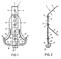
- eine Vorderansicht eines erfindungsgemäßen Aufhängeteils,
- Fig. 2
- eine Seitenansicht des in
Fig. 1 dargestellten Aufhängeteils, - Fig. 3
- eine Vorderansicht eines in eine Tragschiene eingesetzten Aufhängeteils gemäß
Fig. 1 und - Fig. 4
- eine Seitenansicht des in
Fig. 3 dargestellten und in eine Tragschiene eingesetzten Aufhängeteils. - Ein in der Zeichnung dargestelltes Aufhängeteil 1 umfasst einen Grundkörper 2 aus Blech, an welchem mittels Nieten 3 ein U-förmiger Aufhängebügel 4 befestigt ist, dessen oberer U-Schenkel 5 und dessen unterer U-Schenkel 6 miteinander fluchtende Bohrungen 7, 8 aufweisen, durch die ein Abhängedraht (nicht dargestellt) in an sich bekannter Weise geführt werden kann. Die Nieten 3 durchsetzen den U-Boden 9 des Aufhängebügels 4 und den Grundkörper 2.
- An seiner Unterseite weist der Grundkörper 2 Ankeransätze 10 auf, die ebenfalls in bekannter Weise die abgewinkelten Schenkelenden 11 einer zu montierenden Tragschiene 12 untergreifen. Prägerippen 13, 14 verlaufen ausgehend von dem Bereich der Ankeransätze 10 parallel zum Außenrand des Grundkörpers 2 nach oben (Prägerippen 13) beziehungsweise ausgehend von dem Bereich der Ankeransätze 10 in Richtung des unteren Randes 15 des Grundkörpers 2 (Prägerippen 14).
- Unterhalb des Aufhängebügels 4 ist mittels einer Niet 16 ein Federelement 17 an dem Grundkörper 2 befestigt. Das Federelement 17 weist einen oberen Befestigungs-Abschnitt 18 und einen unteren Federabschnitt 19 auf. Das Federelement 17 ist aus einen Blechstreifen gebildet, wobei der Federabschnitt 19 durch Biegen entstanden ist. Der Befestigungs-Abschnitt 18 liegt plan an dem Grundkörper 2 an und wird ebenso wie der Grundkörper 2 von der Niet 16 durchsetzt. Der Befestigungs-Abschnitt 18 ist in etwa auf der Höhe der Ankeransätze 10 angeordnet. Das untere Ende 20 des Befestigungs-Abschnitts 18 verläuft oberhalb der unteren Endabschnitte 21 der Prägerippen 14, das heißt das untere Ende 20 des Befestigungs-Abschnitts 18 ist beabstandet zu dem unteren Rand 15 des Grundkörpers 2 angeordnet. Der an den Befestigungs-Abschnitt 18 angrenzende Federabschnitt 19 liegt nicht an dem Grundkörper 2 an, so dass ein Verschwenken des Federabschnitts 19 relativ zu dem Grundkörper 2 möglich ist. Der Federabschnitt 19 weist eine konstante Krümmung auf und umschließt einen Winkelbereich W von circa 265°. Der Winkelbereich W kann von 190° bis 310° reichen. Der Federabschnitt 19 verläuft ungefähr mit konstantem Abstand um den unteren Rand 15 des Grundkörpers 2. Wie aus
Figuren 4 ersichtlich ist, berührt der untere Rand 15 des Grundkörpers 2 auch im montierten Zustand nicht den Federabschnitt 19. - Die Tragschiene 12 weist mittig eine nach oben vorspringende Erhöhung 22 auf, gegenüber welcher der Federabschnitt 19 abgestützt ist. Die Erhöhung 22 weist einen im Wesentlichen V-förmigen Querschnitt auf. Zwischen der Erhöhung 22 und dem Federabschnitt 19 liegt damit lediglich eine Punktberührung vor.
- Im Folgenden wird eine zweite Ausführungsform der Erfindung beschrieben. Die zweite Ausführungsform unterscheidet sich dahingehend, dass das untere Ende 20 des Befestigungs-Abschnittes 18 entlang des unteren Randes 15 des Grundkörpers 2 verläuft. An den Befestigungs-Abschnitt 18 schließt sich ein Federabschnitt an, welcher einen geraden Abschnitt und einen gekrümmten Abschnitt umfasst. Bei dem geraden Abschnitt handelt es sich um eine Verlängerung des Befestigungs-Abschnittes 18, wobei der gerade Abschnitt nicht an dem Grundkörper 2 anliegt und somit verschwenkbar ist. Der an dem geraden Abschnitt angrenzende gekrümmte Abschnitt umschließt einen Winkelbereich von 100° bis 170°.
- Im Nachfolgenden wird eine dritte Ausführungsform der Erfindung beschrieben. Diese dritte Ausführungsform unterscheidet sich von der zweiten Ausführungsform dahingehend, dass sich an den Befestigungs-Abschnitt direkt ein gekrümmter Abschnitt anschließt. Der gekrümmte Abschnitt bildet den Federabschnitt. Dieser gekrümmte Abschnitt umschließt einen Winkelbereich von 100 ° bis 170°, insbesondere 130°.
Claims (12)
- Ankerförmiges Aufhängeteil für eine im Querschnitt C-förmige Tragschiene (12) einer Unterdecke mit einem Grundkörper (2) und mit an beiden Enden des Grundkörpers (2) nach oben ragenden Ankeransätzen (10), die im Einbauzustand entsprechend nach innen abgewinkelte Schenkelenden (11) der Tragschiene (12) untergreifen können, wobei ein Federelement (17) am unteren Ende des Grundkörpers (2) zum Andrücken der Ankeransätze (10) gegen die abgewinkelten Schenkelenden (11) der Tragschiene (12) vorgesehen ist; wobei das Federelement (17) einen Befestigungs-Abschnitt (18) zur Befestigung des Federelements (17) an dem Grundkörper (2) und einen Federabschnitt (19), der zumindest teilweise gegenüber einem unteren Rand (15) des Grundkörpers (2) übersteht und gegen den Boden (22) der Tragschiene (12) drückt, umfasst, und wobei der Federabschnitt (19) zumindest teilweise gekrümmt ausgebildet ist,
dadurch gekennzeichnet, dass der Federabschnitt (19) ungefähr mit konstantem Abstand um den unteren Rand (15) des Grundkörpers (2) herum verläuft. - Aufhängeteil nach Anspruch 1, dadurch gekennzeichnet, dass das Federelement (17) aus Blech besteht.
- Aufhängeteil nach Anspruch 1, dadurch gekennzeichnet, dass der Federabschnitt (19) einen Winkelbereich W umschließt, für den gilt: 190°<W<310°.
- Aufhängeteil nach einem der Ansprüche 1 bis 3, dadurch gekennzeichnet, dass der Befestigungs-Abschnitt (18) in etwa auf der Höhe der Ankeransätze (10) vorgesehen ist.
- Aufhängeteil nach Anspruch 4, dadurch gekennzeichnet, dass das untere Ende (20) des Befestigungs-Abschnitts (18) beabstandet zu dem unteren Rand (15) des Grundkörpers (2) angeordnet ist.
- Aufhängeteil nach Anspruch 5, dadurch gekennzeichnet, dass das Federelement (17) beabstandet um den unteren Rand (15) des Grundkörpers (2) läuft.
- Aufhängeteil nach einem der Ansprüche 1 bis 6, dadurch gekennzeichnet, dass der Befestigungs-Abschnitt (18) bis zum unteren Rand (15) des Grundkörpers (2) verläuft.
- Aufhängeteil nach Anspruch 7, dadurch gekennzeichnet, dass der Federabschnitt einen geraden Abschnitt umfasst.
- Aufhängeteil nach Anspruch 8, dadurch gekennzeichnet, dass der gerade Abschnitt gegenüber dem unteren Rand (15) des Grundkörpers (2) übersteht.
- Aufhängeteil nach Anspruch 8 oder 9, dadurch gekennzeichnet, dass an den geraden Abschnitt ein gekrümmter Abschnitt angrenzt.
- Aufhängeteil nach Anspruch 7, dadurch gekennzeichnet, dass an den Befestigungs-Abschnitt (18) ein gekrümmter Abschnitt angrenzt.
- Aufhängeteil nach Anspruch 1, dadurch gekennzeichnet, dass das Federelement (17) einstückig mit dem Grundkörper (2) ausgebildet ist.
Applications Claiming Priority (2)
| Application Number | Priority Date | Filing Date | Title |
|---|---|---|---|
| DE10239151 | 2002-08-27 | ||
| DE10239151A DE10239151A1 (de) | 2002-08-27 | 2002-08-27 | Aufhängeteil |
Publications (2)
| Publication Number | Publication Date |
|---|---|
| EP1394331A1 EP1394331A1 (de) | 2004-03-03 |
| EP1394331B1 true EP1394331B1 (de) | 2008-05-14 |
Family
ID=31197398
Family Applications (1)
| Application Number | Title | Priority Date | Filing Date |
|---|---|---|---|
| EP03011790A Expired - Lifetime EP1394331B1 (de) | 2002-08-27 | 2003-05-24 | Aufhängeteil |
Country Status (3)
| Country | Link |
|---|---|
| EP (1) | EP1394331B1 (de) |
| AT (1) | ATE395477T1 (de) |
| DE (2) | DE10239151A1 (de) |
Cited By (1)
| Publication number | Priority date | Publication date | Assignee | Title |
|---|---|---|---|---|
| DE102014206106A1 (de) | 2014-04-01 | 2015-10-01 | Erich R. Vogl | Ankerförmiges Aufhängeteil mit Anpresselement |
Families Citing this family (5)
| Publication number | Priority date | Publication date | Assignee | Title |
|---|---|---|---|---|
| FR2948707A1 (fr) * | 2009-07-30 | 2011-02-04 | Pieces Et Accessoires Ind Pai | Suspente de plafond renforcee |
| FR3014919A1 (fr) * | 2013-12-18 | 2015-06-19 | Novovis | Dispositif de suspente |
| CN109680860B (zh) * | 2019-01-22 | 2024-04-05 | 杭州柏晗装饰设计工程有限公司 | 一种硅钙板吊顶 |
| CN109680859B (zh) * | 2019-01-22 | 2023-09-05 | 佛山市镁鑫金属制品科技有限公司 | 一种铝扣板吊顶 |
| CN111305450B (zh) * | 2020-04-03 | 2022-09-02 | 湖南工学院 | 一种吊顶用吊件 |
Family Cites Families (7)
| Publication number | Priority date | Publication date | Assignee | Title |
|---|---|---|---|---|
| AT372468B (de) * | 1980-10-06 | 1983-10-10 | Rigips Austria Ges Mbh | Einrichtung zur befestigung von verkleidungsplatten |
| DE8525753U1 (de) * | 1985-09-10 | 1985-11-07 | Profil-Vertrieb Gmbh, 7560 Gaggenau | Ankerhänger zum Abhängen C-förmiger Deckentrageschienen |
| DE8806310U1 (de) * | 1988-05-13 | 1988-07-14 | Vogl, Erich R., 8535 Emskirchen | Vorrichtung zur abstandseinstellbaren Befestigung eines Trägers, insbesondere für abgehängte Decken od. dgl., an einem hängend befestigten Tragseil od. dgl. |
| DE9105466U1 (de) * | 1991-05-03 | 1991-06-13 | Richter-System GmbH & Co KG, 6103 Griesheim | Abhänger mit C-Profilschiene |
| DE9315487U1 (de) | 1993-10-13 | 1993-12-16 | Vogl, Erich R., 91448 Emskirchen | Ankerförmiges Aufhängeteil |
| DE29617249U1 (de) * | 1996-10-04 | 1997-02-06 | Richter-System GmbH & Co KG, 64347 Griesheim | Abhänger für CD-Schienen |
| DE20116627U1 (de) * | 2001-10-10 | 2002-01-24 | Huwer KG, 55758 Oberreidenbach | Ankerelement |
-
2002
- 2002-08-27 DE DE10239151A patent/DE10239151A1/de not_active Withdrawn
-
2003
- 2003-05-24 DE DE50309826T patent/DE50309826D1/de not_active Expired - Lifetime
- 2003-05-24 EP EP03011790A patent/EP1394331B1/de not_active Expired - Lifetime
- 2003-05-24 AT AT03011790T patent/ATE395477T1/de active
Cited By (2)
| Publication number | Priority date | Publication date | Assignee | Title |
|---|---|---|---|---|
| DE102014206106A1 (de) | 2014-04-01 | 2015-10-01 | Erich R. Vogl | Ankerförmiges Aufhängeteil mit Anpresselement |
| EP2927384A1 (de) | 2014-04-01 | 2015-10-07 | Erich R. Vogl | Ankerförmiges aufhängeteil mit anpresselement |
Also Published As
| Publication number | Publication date |
|---|---|
| ATE395477T1 (de) | 2008-05-15 |
| EP1394331A1 (de) | 2004-03-03 |
| DE10239151A1 (de) | 2004-03-11 |
| DE50309826D1 (de) | 2008-06-26 |
Similar Documents
| Publication | Publication Date | Title |
|---|---|---|
| EP2259954B1 (de) | Wischblatt | |
| EP2703237B1 (de) | Baugruppe mit einem Regensensor und einer Halteklammer für den Regensensor. | |
| EP2110894B1 (de) | Elektrischer Steckverbinder und Verriegelungsbügel zur Verriegelung zweier elektrischer Gehäuseteile | |
| DE602004007097T3 (de) | Scheibenwischervorrichtung | |
| WO2007104530A1 (de) | Befestigungselement, montagewerkzeug und montageset | |
| DE2738672A1 (de) | Fensterheber, insbesondere fuer kraftfahrzeuge | |
| EP0596306A2 (de) | Abdeckleiste für eine in ein Fahrzeugdach eingelassene Rinne | |
| EP1394331B1 (de) | Aufhängeteil | |
| DE19730600A1 (de) | Stulpschienenbeschlag | |
| WO2008077858A1 (de) | Halterung | |
| DE3625063C2 (de) | ||
| EP2045405B1 (de) | Betätigungsplatte für eine Betätigungsvorrichtung einer Spüleinrichtung | |
| EP0580822B1 (de) | Wischarm, insbesondere zur reinigung von scheiben von kraftfahrzeugen | |
| DE202023104721U1 (de) | Verbindungsmechanismus zur schnellen Montage einer Platte | |
| EP1140591A1 (de) | Haltefeder zum herstellen einer gelenkverbindung eines wischblatts mit einem wischarm eines fahrzeugs und entsprechende wischvorrichtung | |
| DE19748704B4 (de) | Befestigungsvorrichtung für im Laugenbehälter einer Waschmaschine eingebaute Heizstäbe | |
| EP0264570B1 (de) | Potentiometer | |
| DE102007044964B4 (de) | Rasterbefestigung für schmale Einbauleuchten | |
| EP2300677A1 (de) | Scharniertopf für möbelscharniere | |
| DE102022122055B4 (de) | Lenkrad mit einem Airbagmodul | |
| DE102022105561B4 (de) | Haken zur aufnahme einer welle | |
| DE4413747C2 (de) | Abdeckschiene zur Befestigung von Leuchten oder Leuchtenteilen | |
| DE9315487U1 (de) | Ankerförmiges Aufhängeteil | |
| EP2927384B1 (de) | Ankerförmiges aufhängeteil mit anpresselement | |
| EP0520189A1 (de) | Ordnermechanik |
Legal Events
| Date | Code | Title | Description |
|---|---|---|---|
| PUAI | Public reference made under article 153(3) epc to a published international application that has entered the european phase |
Free format text: ORIGINAL CODE: 0009012 |
|
| AK | Designated contracting states |
Kind code of ref document: A1 Designated state(s): AT BE BG CH CY CZ DE DK EE ES FI FR GB GR HU IE IT LI LU MC NL PT RO SE SI SK TR |
|
| AX | Request for extension of the european patent |
Extension state: AL LT LV MK |
|
| 17P | Request for examination filed |
Effective date: 20040820 |
|
| AKX | Designation fees paid |
Designated state(s): AT BE BG CH CY CZ DE DK EE ES FI FR GB GR HU IE IT LI LU MC NL PT RO SE SI SK TR |
|
| 17Q | First examination report despatched |
Effective date: 20060510 |
|
| GRAP | Despatch of communication of intention to grant a patent |
Free format text: ORIGINAL CODE: EPIDOSNIGR1 |
|
| GRAS | Grant fee paid |
Free format text: ORIGINAL CODE: EPIDOSNIGR3 |
|
| GRAA | (expected) grant |
Free format text: ORIGINAL CODE: 0009210 |
|
| AK | Designated contracting states |
Kind code of ref document: B1 Designated state(s): AT BE BG CH CY CZ DE DK EE ES FI FR GB GR HU IE IT LI LU MC NL PT RO SE SI SK TR |
|
| REG | Reference to a national code |
Ref country code: GB Ref legal event code: FG4D Free format text: NOT ENGLISH |
|
| REG | Reference to a national code |
Ref country code: CH Ref legal event code: EP |
|
| REG | Reference to a national code |
Ref country code: IE Ref legal event code: FG4D Free format text: LANGUAGE OF EP DOCUMENT: GERMAN |
|
| REF | Corresponds to: |
Ref document number: 50309826 Country of ref document: DE Date of ref document: 20080626 Kind code of ref document: P |
|
| PG25 | Lapsed in a contracting state [announced via postgrant information from national office to epo] |
Ref country code: SI Free format text: LAPSE BECAUSE OF FAILURE TO SUBMIT A TRANSLATION OF THE DESCRIPTION OR TO PAY THE FEE WITHIN THE PRESCRIBED TIME-LIMIT Effective date: 20080514 |
|
| PG25 | Lapsed in a contracting state [announced via postgrant information from national office to epo] |
Ref country code: FI Free format text: LAPSE BECAUSE OF FAILURE TO SUBMIT A TRANSLATION OF THE DESCRIPTION OR TO PAY THE FEE WITHIN THE PRESCRIBED TIME-LIMIT Effective date: 20080514 Ref country code: ES Free format text: LAPSE BECAUSE OF FAILURE TO SUBMIT A TRANSLATION OF THE DESCRIPTION OR TO PAY THE FEE WITHIN THE PRESCRIBED TIME-LIMIT Effective date: 20080825 |
|
| NLV1 | Nl: lapsed or annulled due to failure to fulfill the requirements of art. 29p and 29m of the patents act | ||
| PG25 | Lapsed in a contracting state [announced via postgrant information from national office to epo] |
Ref country code: NL Free format text: LAPSE BECAUSE OF FAILURE TO SUBMIT A TRANSLATION OF THE DESCRIPTION OR TO PAY THE FEE WITHIN THE PRESCRIBED TIME-LIMIT Effective date: 20080514 |
|
| BERE | Be: lapsed |
Owner name: VOGL, ERICH R. Effective date: 20080531 |
|
| PG25 | Lapsed in a contracting state [announced via postgrant information from national office to epo] |
Ref country code: MC Free format text: LAPSE BECAUSE OF NON-PAYMENT OF DUE FEES Effective date: 20080531 |
|
| REG | Reference to a national code |
Ref country code: IE Ref legal event code: FD4D |
|
| PG25 | Lapsed in a contracting state [announced via postgrant information from national office to epo] |
Ref country code: DK Free format text: LAPSE BECAUSE OF FAILURE TO SUBMIT A TRANSLATION OF THE DESCRIPTION OR TO PAY THE FEE WITHIN THE PRESCRIBED TIME-LIMIT Effective date: 20080514 Ref country code: SE Free format text: LAPSE BECAUSE OF FAILURE TO SUBMIT A TRANSLATION OF THE DESCRIPTION OR TO PAY THE FEE WITHIN THE PRESCRIBED TIME-LIMIT Effective date: 20080814 Ref country code: IE Free format text: LAPSE BECAUSE OF FAILURE TO SUBMIT A TRANSLATION OF THE DESCRIPTION OR TO PAY THE FEE WITHIN THE PRESCRIBED TIME-LIMIT Effective date: 20080514 Ref country code: CZ Free format text: LAPSE BECAUSE OF FAILURE TO SUBMIT A TRANSLATION OF THE DESCRIPTION OR TO PAY THE FEE WITHIN THE PRESCRIBED TIME-LIMIT Effective date: 20080514 Ref country code: PT Free format text: LAPSE BECAUSE OF FAILURE TO SUBMIT A TRANSLATION OF THE DESCRIPTION OR TO PAY THE FEE WITHIN THE PRESCRIBED TIME-LIMIT Effective date: 20081014 |
|
| PG25 | Lapsed in a contracting state [announced via postgrant information from national office to epo] |
Ref country code: RO Free format text: LAPSE BECAUSE OF FAILURE TO SUBMIT A TRANSLATION OF THE DESCRIPTION OR TO PAY THE FEE WITHIN THE PRESCRIBED TIME-LIMIT Effective date: 20080514 Ref country code: SK Free format text: LAPSE BECAUSE OF FAILURE TO SUBMIT A TRANSLATION OF THE DESCRIPTION OR TO PAY THE FEE WITHIN THE PRESCRIBED TIME-LIMIT Effective date: 20080514 |
|
| PLBE | No opposition filed within time limit |
Free format text: ORIGINAL CODE: 0009261 |
|
| STAA | Information on the status of an ep patent application or granted ep patent |
Free format text: STATUS: NO OPPOSITION FILED WITHIN TIME LIMIT |
|
| PG25 | Lapsed in a contracting state [announced via postgrant information from national office to epo] |
Ref country code: BE Free format text: LAPSE BECAUSE OF NON-PAYMENT OF DUE FEES Effective date: 20080531 |
|
| 26N | No opposition filed |
Effective date: 20090217 |
|
| GBPC | Gb: european patent ceased through non-payment of renewal fee |
Effective date: 20080814 |
|
| PG25 | Lapsed in a contracting state [announced via postgrant information from national office to epo] |
Ref country code: EE Free format text: LAPSE BECAUSE OF FAILURE TO SUBMIT A TRANSLATION OF THE DESCRIPTION OR TO PAY THE FEE WITHIN THE PRESCRIBED TIME-LIMIT Effective date: 20080514 Ref country code: BG Free format text: LAPSE BECAUSE OF FAILURE TO SUBMIT A TRANSLATION OF THE DESCRIPTION OR TO PAY THE FEE WITHIN THE PRESCRIBED TIME-LIMIT Effective date: 20080814 |
|
| REG | Reference to a national code |
Ref country code: FR Ref legal event code: ST Effective date: 20090331 |
|
| PG25 | Lapsed in a contracting state [announced via postgrant information from national office to epo] |
Ref country code: FR Free format text: LAPSE BECAUSE OF NON-PAYMENT OF DUE FEES Effective date: 20080602 Ref country code: IT Free format text: LAPSE BECAUSE OF FAILURE TO SUBMIT A TRANSLATION OF THE DESCRIPTION OR TO PAY THE FEE WITHIN THE PRESCRIBED TIME-LIMIT Effective date: 20080514 |
|
| PG25 | Lapsed in a contracting state [announced via postgrant information from national office to epo] |
Ref country code: GB Free format text: LAPSE BECAUSE OF NON-PAYMENT OF DUE FEES Effective date: 20080814 |
|
| PG25 | Lapsed in a contracting state [announced via postgrant information from national office to epo] |
Ref country code: HU Free format text: LAPSE BECAUSE OF FAILURE TO SUBMIT A TRANSLATION OF THE DESCRIPTION OR TO PAY THE FEE WITHIN THE PRESCRIBED TIME-LIMIT Effective date: 20081115 Ref country code: CY Free format text: LAPSE BECAUSE OF FAILURE TO SUBMIT A TRANSLATION OF THE DESCRIPTION OR TO PAY THE FEE WITHIN THE PRESCRIBED TIME-LIMIT Effective date: 20080514 Ref country code: LU Free format text: LAPSE BECAUSE OF NON-PAYMENT OF DUE FEES Effective date: 20080524 |
|
| PG25 | Lapsed in a contracting state [announced via postgrant information from national office to epo] |
Ref country code: TR Free format text: LAPSE BECAUSE OF FAILURE TO SUBMIT A TRANSLATION OF THE DESCRIPTION OR TO PAY THE FEE WITHIN THE PRESCRIBED TIME-LIMIT Effective date: 20080514 |
|
| PG25 | Lapsed in a contracting state [announced via postgrant information from national office to epo] |
Ref country code: GR Free format text: LAPSE BECAUSE OF FAILURE TO SUBMIT A TRANSLATION OF THE DESCRIPTION OR TO PAY THE FEE WITHIN THE PRESCRIBED TIME-LIMIT Effective date: 20080815 |
|
| PGFP | Annual fee paid to national office [announced via postgrant information from national office to epo] |
Ref country code: AT Payment date: 20120426 Year of fee payment: 10 |
|
| PGFP | Annual fee paid to national office [announced via postgrant information from national office to epo] |
Ref country code: CH Payment date: 20130422 Year of fee payment: 11 |
|
| REG | Reference to a national code |
Ref country code: CH Ref legal event code: PL |
|
| REG | Reference to a national code |
Ref country code: AT Ref legal event code: MM01 Ref document number: 395477 Country of ref document: AT Kind code of ref document: T Effective date: 20140524 |
|
| PG25 | Lapsed in a contracting state [announced via postgrant information from national office to epo] |
Ref country code: LI Free format text: LAPSE BECAUSE OF NON-PAYMENT OF DUE FEES Effective date: 20140531 Ref country code: CH Free format text: LAPSE BECAUSE OF NON-PAYMENT OF DUE FEES Effective date: 20140531 |
|
| PG25 | Lapsed in a contracting state [announced via postgrant information from national office to epo] |
Ref country code: AT Free format text: LAPSE BECAUSE OF NON-PAYMENT OF DUE FEES Effective date: 20140524 |
|
| PGFP | Annual fee paid to national office [announced via postgrant information from national office to epo] |
Ref country code: DE Payment date: 20170720 Year of fee payment: 15 |
|
| REG | Reference to a national code |
Ref country code: DE Ref legal event code: R119 Ref document number: 50309826 Country of ref document: DE |
|
| PG25 | Lapsed in a contracting state [announced via postgrant information from national office to epo] |
Ref country code: DE Free format text: LAPSE BECAUSE OF NON-PAYMENT OF DUE FEES Effective date: 20181201 |