EP1389284B1 - Module de commutation de securite servant a verifier la capacite d'interruption d'un element de commutation dans un module de commutation de securite - Google Patents
Module de commutation de securite servant a verifier la capacite d'interruption d'un element de commutation dans un module de commutation de securite Download PDFInfo
- Publication number
- EP1389284B1 EP1389284B1 EP02716833A EP02716833A EP1389284B1 EP 1389284 B1 EP1389284 B1 EP 1389284B1 EP 02716833 A EP02716833 A EP 02716833A EP 02716833 A EP02716833 A EP 02716833A EP 1389284 B1 EP1389284 B1 EP 1389284B1
- Authority
- EP
- European Patent Office
- Prior art keywords
- switching
- safety
- control device
- switching elements
- module
- Prior art date
- Legal status (The legal status is an assumption and is not a legal conclusion. Google has not performed a legal analysis and makes no representation as to the accuracy of the status listed.)
- Expired - Lifetime
Links
Images

Classifications
-
- H—ELECTRICITY
- H01—ELECTRIC ELEMENTS
- H01H—ELECTRIC SWITCHES; RELAYS; SELECTORS; EMERGENCY PROTECTIVE DEVICES
- H01H9/00—Details of switching devices, not covered by groups H01H1/00 - H01H7/00
- H01H9/54—Circuit arrangements not adapted to a particular application of the switching device and for which no provision exists elsewhere
- H01H9/548—Electromechanical and static switch connected in series
-
- F—MECHANICAL ENGINEERING; LIGHTING; HEATING; WEAPONS; BLASTING
- F16—ENGINEERING ELEMENTS AND UNITS; GENERAL MEASURES FOR PRODUCING AND MAINTAINING EFFECTIVE FUNCTIONING OF MACHINES OR INSTALLATIONS; THERMAL INSULATION IN GENERAL
- F16P—SAFETY DEVICES IN GENERAL; SAFETY DEVICES FOR PRESSES
- F16P3/00—Safety devices acting in conjunction with the control or operation of a machine; Control arrangements requiring the simultaneous use of two or more parts of the body
-
- H—ELECTRICITY
- H01—ELECTRIC ELEMENTS
- H01H—ELECTRIC SWITCHES; RELAYS; SELECTORS; EMERGENCY PROTECTIVE DEVICES
- H01H47/00—Circuit arrangements not adapted to a particular application of the relay and designed to obtain desired operating characteristics or to provide energising current
- H01H47/002—Monitoring or fail-safe circuits
- H01H47/004—Monitoring or fail-safe circuits using plural redundant serial connected relay operated contacts in controlled circuit
-
- H—ELECTRICITY
- H03—ELECTRONIC CIRCUITRY
- H03K—PULSE TECHNIQUE
- H03K17/00—Electronic switching or gating, i.e. not by contact-making and –breaking
- H03K17/18—Modifications for indicating state of switch
Definitions
- the present invention relates to a safety switching module for safe shutdown of an electrical load, comprising a first and a second switching control means, a first and a second switching element arranged in series, which form a first current path for supplying the load, wherein the first switching element of the first switching control means and the second switching element is controllable by the second switching control device, and an evaluation and control unit for testing the breaking capacity of at least one switching element.
- safety switching modules or safety switching devices are well known.
- the applicant offers safety switching devices in different variants under the name "PNOZ".
- PNOZ safety switching devices in different variants under the name "PNOZ”.
- DE 100 11 211 the applicant is, for example, such a safety switching device disclosed.
- safety switching devices are mainly used in the industrial sector to switch off and safely switch off electrically driven machines, such as, for example, a press or a milling tool, a valve terminal for pneumatic or hydraulic control systems or output modules of a PLC. They serve, in particular in conjunction with a mechanically actuated emergency stop button, to switch off the machine quickly and safely in an emergency situation.
- the power supply of the machine to be switched off is guided via two switching elements connected in series. As soon as only one of the two switching elements opens, the power supply of the machine is interrupted.
- an evaluation and control unit In order to carry out a check of the switching capacity of the switching elements in the operation of such a safety switching device, an evaluation and control unit is provided which briefly turns off the switching elements individually and thereby detects and evaluates the output signal (readback signal) of the switching elements. Based on this evaluation, the evaluation and control unit can determine whether each switching element is able to supply the electrical power to the machine, i. generally to interrupt the electrical load in an emergency situation. In order not to affect the electrical load through this testing process, the switching element is turned off only for a very short period of time, which is not "visible" to the load.
- the object of the present invention is to provide a safety switching module of the aforementioned type, which allows a simple way of testing the Abschaltterrorisms the switching elements even with large currents to be switched and / or capacitive or inductive loads.
- a third and a fourth switching element are provided, which are arranged in series with each other and parallel to the series circuit of the first and second switching element and form a second current path, wherein the third switching element of the first switching control means and the fourth switching element of the second switching control means is controllable, and that the evaluation and control unit performs the examination of both switching elements in alternately one of the two current paths, so that then the other of the two current paths supplies the load.
- switch-off pulse is not applied to the load, longer switch-off pulses are possible. This means that with the structure according to the invention in addition to semiconductor devices and electromechanical switching elements can be tested while the load is turned on.
- Another advantage of the structure according to the invention is also to be seen in the fact that the security of supply is increased, since in case of failure of a current path, for example. Due to an alloyed semiconductor switching element with appropriate control, a secure supply of the load is still possible.
- the first and the third switching element is designed as a semiconductor switching element.
- the second and the fourth switching element is designed as an electromechanical switching element, preferably as a relay.
- the switching control device is designed with two channels.
- This measure has the advantage that the safety of the safety switching module is further increased.
- the evaluation and control unit is connected to each of the two current paths such that it can read out a signal between the first and the second or the third and the fourth switching element.
- This measure has the advantage that the evaluation and control unit can detect the breaking capacity of both switching elements in the respective current path.
- evaluation and control unit is designed such that they generate a short turn-off and either the first or the third Can supply switching element to turn this off briefly.
- this switch-off pulse is modulated onto the control signal generated by the switch control device.
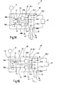
- Fig. 1A is shown in a schematic representation of a safety switching device and designated by the reference numeral 10.
- the safety switching device 10 comprises a schematically indicated safe evaluation and control unit 12.
- This evaluation and control unit 12 is constructed from known components, as they are also used in the aforementioned safety relay "PNOZ" of the applicant.
- the task of this evaluation and control unit is to reliably evaluate supplied switching signals, for example from an emergency stop switch 14, and to generate corresponding output signals.
- the evaluation and control unit 12 is constructed in the embodiment shown two channels, wherein the two channels are denoted by the reference numerals 16a and 16b. Of course, other embodiments of the evaluation and control unit 12 are possible. For a more detailed explanation of such an evaluation and control unit 12 is, for example, on the book “Machine Safety”, Winfried Gräf, Wegig-Verlag, 1997, reference is made.
- the safety switching device 10 further comprises per channel a control device (switching control device) 20A and 20B, each receiving a control signal from the corresponding evaluation and control unit 16a and 16b via lines 22.
- a control device switching control device
- the lines 22 may also be multi-core bus lines.
- the control device 20 generates depending on the supplied control signals from the evaluation and control unit 12 drive signals, the switching elements 24.1 to 24.4 are supplied.
- the Fig. 1A indicates that the drive means 20A generates two drive signals, which are supplied to the two switching elements 24.1 and 24.3.
- the drive device 20B also generates two drive signals, which, however, are supplied to the two switching elements 24.2 and 24.4.
- the two control signals generated by the control device 20A and 20B are the same in each case, so that in the normal operation of the safety switching device 10, the switching element pairs 24.1 and 24.3 or 24.2 and 24.4 have the same switching state.
- the total of four switching elements 24.1 to 24.4 are arranged so that two identical current paths 26.1 and 26.2 are formed.
- the two switching elements 24.1 and 24.2 connected in series, so that they form the first current path 26.1, while the other two switching elements 24.3 and 24.4 are also connected in series and form the second current path 26.2.
- From the illustration in Fig. 1A clearly shows that the two current paths 26.1, 26.2 are parallel to each other.
- the two current paths 26.1, 26.2 connect an input terminal 30 of the safety switching device 10 to an output terminal 33.
- the switching elements 24 are switched on, an ohmic connection is thus created between the input terminal 30 and the output terminal 33, whereby a corresponding current can flow over both current paths 26.
- the safety switching device 10 has a further output terminal 35 and a further input terminal 37. From the Fig. 1A It can be seen that there is an electrical connection between the input terminal 37 and the output terminal 35.
- a DC voltage source 41 is connected to the two input terminals 30, 37, which provides, for example, a voltage of 24 volts between the two terminals 30, 37, the input terminal 30 at a positive potential and the input terminal 37 at a reference potential, eg. 0 volts lies.
- the load to be switched by the safety switching device 10 is in Fig. 1A shown schematically and identified by the reference numeral 43.
- the load 43 is a load of high power, for example, valve terminals for pneumatic or hydraulic controls, or output modules of a PLC control, which requires a current> 8 amps.
- the load 43 is connected between the output terminals 33 and 35. It follows that when switched switching elements 24, a current flow from the DC voltage source 41 via the input terminal 30, the two current paths 26.1, 26.2, the output terminal 33, the load 43, the output terminal 35, and the input terminal 37 back to the DC voltage source 41 results.
- the evaluation and control unit 12 If, for example, the emergency stop switch 14 is actuated, the evaluation and control unit 12 generates control signals which are converted by the two drive devices 20A, 20B into corresponding drive signals. These drive signals cause switching elements 24 to be switched off in order to switch off the current paths 26.1, 26.2. Thus, the load 43 is disconnected from the DC power source 41.
- the breaking capacity of the switching elements is now tested by switching off the two switching elements in one current path for a short period of time while the switching elements in the other current path maintain their switching state.
- the short turn-off of the switching elements in a current path causes the potential between the two tested switching elements to change, provided that the switching elements are in order. This potential change can be the evaluation and control unit 12 recognize and evaluate accordingly. If, for example, the switching element 24.1 can no longer be opened in the first current path 26.1, the potential does not change during the short test phase, which is recognized by the evaluation and control unit 12 as an error. An immediate shutdown of the entire safety relay and thus the load 43 would be the result.
- Fig. 1A can still recognize connections shown in dashed lines, which extend from the two evaluation and control units 16A, B to the drive means 20A, B and from the readback lines to the evaluation and control units 16A, B. These connections serve to continue the two-channel structure of the safety relay; these connections allow each evaluation and control unit 16A, B, all four switching elements 24.1-24.4 to control and check.
- Fig. 1B is a safety switching device 10 'is shown, with respect to the function of the already with reference to the Fig. 1A shown safety relay 10 corresponds. A detailed description should therefore be omitted here. Also the design of the safety relay 10 'does not differ from that of the safety switching device 10. The only difference is that the safety switching device 10' has been divided into two modules 50, 51.
- the module 50 which is referred to below as a safety switching module, comprises the drive means 20A, 20B and the switching elements 24, which are arranged in the two current paths 26.1, 26.2.
- the module 51 which is referred to below as the evaluation and control module, comprises the evaluation and control unit 12, the control signals to the input terminals 53 of the safety switching module 50 can be fed.
- the safety switching module 50 can be connected as an additional module for switching large currents to existing safety relays.
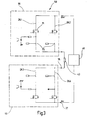
- Dashed lines show the individual function blocks, namely the two drive devices 20A, 20B and the switching elements 24.1 to 24.4.
- the drive means 20A comprises in the present embodiment, two drive units 61, 62 which generate depending on corresponding input signals in each case an output signal which is respectively supplied to an optocoupler 63 and 64 respectively.
- the outputs of the two optical couplers 63, 64 are connected in series and serve to control the switching element 24.1.
- the control input of the switching element 24.1 is connected via the outputs of the opto-couplers 63, 64 to a positive potential. If corresponding control signals are present at the inputs of the two optocouplers 63, 64, the outputs of the two optocouplers are connected to one another, so that then the switching element 24.1 receives a drive signal with a positive potential and closes on the basis thereof. This is the normal mode of operation of the safety switch module 50 to power the load 43.
- the switching element 24.1 is designed as a semiconductor switching element, preferably as a field effect transistor 71.
- the second switching element 24.2 in the same current path 26.1 as an electromechanical switching element, preferably designed as a relay 73.
- This relay 73 is controlled via corresponding drive units 61, 62. Since the relay 73 itself provides a galvanic isolation to the driver 20B, the use of optocouplers 63, 64 can be dispensed with.
- control of the field effect transistor 71 and the relay 73 is two-channel. Only if both drive units 61, 62 a corresponding Generate control signal, the switching element 24.1, 24.2 is closed.
- the evaluation and control unit 12 checks the breaking capacity of the switching elements 24 by briefly switching off the switching elements of a current path
- a signal between the two switching elements 24.1, 24.2 is tapped off via the line 45 and fed to an optocoupler 83.
- This optocoupler 83 generates a readback signal which is fed to the evaluation and control unit 12.
- This readback signal provides information on whether the FET 71 and the contact 73 are switched off during the test phase. Do both switching elements 71 and 73, the security is guaranteed; however, if they fail to do so, the FET 71 or contact 73 will be faulty, with the result that the entire safety switch module 50 must be turned off so that the load 43 is placed in the safe state.
- the structure of the second current path 26.2 corresponds exactly to that of the current path 26.1, so that it is possible to dispense with a repeated description at this point. For clarity, some elements have been combined to form a functional block, for example.
- the Abschaltgrin the FET 71 and the contact 24.4 is carried out by modulating a short turn-off on the drive signal. An appropriate readback signal is then generated via an optocoupler 83.
- the switching elements of a current path are diversified. This makes it possible to exclude faults in a current path due to the same causes.
- semiconductor switching elements or electromechanical switching elements can be used.
- FIG. 3 Another embodiment of a safety switching module is in Fig. 3 shown and designated by the reference numeral 50 '.
- safety switching module 50 is a two-pole version of a safety switching module. That is, the load 43 between two safety switch modules 50, as in Fig. 2 represented lies.
- the connection between the terminal 35 and the terminal 37 is thus not directly, but also via two current paths 26.3 and 26.4, which are constructed in an interchangeable arrangement to the two current paths 26.1 and 26.2.
- the operation corresponds to the safety switch module 50, as in Fig. 2 has been shown and described, so that can be dispensed with a repeated description.
- the advantage is that the load can be switched off safely even with a 24V short circuit.
Claims (10)
- Module de commutation de sécurité destiné à interrompre avec fiabilité une charge électrique (43), comprenant un premier et un second dispositifs de commande de sécurité (20A, 20B), un premier élément de commutation et un deuxième élément de commutation (24.1, 24.2) disposé en série par rapport à celui-ci, qui forment un premier trajet de courant (26.1) destiné à alimenter la charge, le premier élément de commutation (24.1) pouvant être commandé par le premier dispositif de commande de commutation (20A) et le deuxième élément de commutation (24.2) pouvant être commandé par le second dispositif de commande de commutation (20B), et comprenant un dispositif d'analyse et de commande (12) destiné à surveiller la capacité d'interruption d'au moins un élément de commutation, caractérisé en ce qu'un troisième et un quatrième éléments de commutation (24.3, 24.4) sont prévus, qui sont disposés en série les uns par rapport aux autres et parallèlement au branchement en série des premier et deuxième éléments de commutation (24.1, 24.2) et forment un second trajet de courant (26.2), le troisième élément de commutation (24.3) pouvant être commandé par le premier dispositif de commande de commutation (20A) et le quatrième élément de commutation (24.4) pouvant être commandé par le second dispositif de commande de commutation (20B), et en ce que le dispositif d'analyse et de commande (12) réalise la surveillance des éléments de commutation (24) tout à tour dans un des deux trajets de courant (26.1, 26.2), de sorte que l'autre des deux trajets de courant (26.2, 26.1) amène la charge (43).
- Module de commutation de sécurité selon la revendication 1, caractérisé en ce que le premier et le troisième éléments de commutation (24.1, 24.3) sont conçus comme des éléments de commutation à semi-conducteur (71).
- Module de commutation de sécurité selon la revendication 1 ou 2, caractérisé en ce que le deuxième et le quatrième éléments de commutation (24.2, 24.4) sont conçus comme un élément de commutation électromécanique (73), de préférence comme un relais.
- Module de commutation de sécurité selon l'une quelconque des revendications précédentes, caractérisé en ce que les dispositifs de commande de commutation (20A, 20B, 61, 62) sont conçus avec deux canaux.
- Module de commutation de sécurité selon l'une quelconque des revendications précédentes, caractérisé en ce que les trajets de courant sont reliés sur un côté à une tension d'alimentation et sur l'autre côté à la charge.
- Module de commutation de sécurité selon l'une quelconque des revendications précédentes, caractérisé en ce que le dispositif d'analyse et de commande (12, 83) est relié à chacun des deux trajets de courant (26.1, 26.2) entre le premier et le deuxième (24.1, 24.2) et/ou le troisième et le quatrième éléments de commutation (24.3, 24.4).
- Module de commutation de sécurité selon l'une quelconque des revendications précédentes, caractérisé en ce que le dispositif d'analyse et de commande produit une courte impulsion d'interruption et l'amène soit au premier et au deuxième éléments de commutation (24.1, 24.2) soit au troisième et au quatrième éléments de commutation (24.3, 24.4), afin de les interrompre brièvement.
- Module de commutation de sécurité selon la revendication 6, caractérisé en ce que l'impulsion d'interruption est modulée sur le signal du dispositif de commande de commutation.
- Module de commutation de sécurité selon l'une quelconque des revendications précédentes, caractérisé en ce que les éléments de commutation (24.1-24.4) sont des éléments de commutation électromécaniques, de préférence des relais.
- Module de commutation de sécurité selon l'une quelconque des revendications 1 à 7, caractérisé en ce que les éléments de commutation (24.1-24.4) sont des éléments de commutation à semi-conducteur.
Applications Claiming Priority (3)
| Application Number | Priority Date | Filing Date | Title |
|---|---|---|---|
| DE10127233A DE10127233C1 (de) | 2001-05-22 | 2001-05-22 | Sicherheitsschaltmodul und Verfahren zur Prüfung des Abschaltvermögens eines Schaltelements in einem Sicherheitsschaltmodul |
| DE10127233 | 2001-05-22 | ||
| PCT/EP2002/002840 WO2002095282A2 (fr) | 2001-05-22 | 2002-03-14 | Module de commutation de securite et procede servant a verifier la capacite d'interruption d'un element de commutation dans un module de commutation de securite |
Publications (2)
| Publication Number | Publication Date |
|---|---|
| EP1389284A2 EP1389284A2 (fr) | 2004-02-18 |
| EP1389284B1 true EP1389284B1 (fr) | 2008-07-30 |
Family
ID=7687234
Family Applications (1)
| Application Number | Title | Priority Date | Filing Date |
|---|---|---|---|
| EP02716833A Expired - Lifetime EP1389284B1 (fr) | 2001-05-22 | 2002-03-14 | Module de commutation de securite servant a verifier la capacite d'interruption d'un element de commutation dans un module de commutation de securite |
Country Status (8)
| Country | Link |
|---|---|
| US (1) | US7187091B2 (fr) |
| EP (1) | EP1389284B1 (fr) |
| JP (1) | JP4191494B2 (fr) |
| AT (1) | ATE403106T1 (fr) |
| AU (1) | AU2002247759A1 (fr) |
| DE (1) | DE10127233C1 (fr) |
| ES (1) | ES2311596T3 (fr) |
| WO (1) | WO2002095282A2 (fr) |
Cited By (1)
| Publication number | Priority date | Publication date | Assignee | Title |
|---|---|---|---|---|
| DE202015103339U1 (de) | 2015-06-25 | 2016-09-30 | Weidmüller Interface GmbH & Co. KG | Schaltungsanordnung für einen sicheren digitalen Schaltausgang |
Families Citing this family (35)
| Publication number | Priority date | Publication date | Assignee | Title |
|---|---|---|---|---|
| DE10216226A1 (de) | 2002-04-08 | 2003-10-30 | Pilz Gmbh & Co | Vorrichtung zum fehlersicheren Abschalten eines elektrischen Verbrauchers, insbesondere in industriellen Produktionsanlagen |
| US7193379B2 (en) | 2003-10-20 | 2007-03-20 | Wabtec Holding Corp. | Electronic circuit arrangement for switching an electrical load in a fail safe manner |
| DE502005009527D1 (de) * | 2004-04-19 | 2010-06-17 | Pilz Gmbh & Co Kg | Meldegerät für eine sicherheitsschaltung |
| GB2429347B (en) * | 2005-04-01 | 2007-08-08 | Westinghouse Airbrake Technolo | Electronic circuit arrangement for switching an electrical load in a fail safe manner |
| EP1911058B1 (fr) | 2005-08-02 | 2008-12-03 | Phoenix Contact GmbH & Co. KG | Commutateur de securite pour commander un dispositif relevant de la securite, afin de le mettre dans un etat de securite |
| DE102006061476B3 (de) * | 2006-12-23 | 2008-06-26 | Berger Lahr Gmbh & Co. Kg | Elektrische Steuerung |
| US20090050453A1 (en) * | 2007-08-23 | 2009-02-26 | Honeywell International Inc. | Explosion proof safety switch apparatus |
| DE102009017275B4 (de) | 2009-04-11 | 2014-01-09 | Festo Ag & Co. Kg | Vorrichtung zur Überwachung der Schaltfähigkeit wenigstens eines zur Schaltung eines elektrischen Verbrauchers dienenden Halbleiterschalters |
| DE102010004524B4 (de) | 2010-01-14 | 2017-01-19 | Festo Ag & Co. Kg | Vorrichtung zur elektrischen Stromkreisüberwachung |
| DE102010007784A1 (de) | 2010-02-12 | 2011-08-18 | FESTO AG & Co. KG, 73734 | Vorrichtung zur elektrischen Stromkreisüberwachung |
| DE102011086756A1 (de) | 2010-11-23 | 2012-05-24 | Continental Teves Ag & Co. Ohg | Verfahren zur Fehlererkennung eines Bedienschalters zur Auslösung einer Fahrzeugfunktion eines Fahrzeuges sowie Bedienschalter zur Durchführung des Verfahrens |
| EP2461342B1 (fr) * | 2010-12-06 | 2015-01-28 | Siemens Aktiengesellschaft | Module de commutation protégé contre les erreurs |
| GB2486493B (en) * | 2010-12-17 | 2016-06-15 | Ge Aviat Systems Ltd | Switching circuits and methods of testing |
| JP5546524B2 (ja) * | 2011-12-06 | 2014-07-09 | オムロンオートモーティブエレクトロニクス株式会社 | 車両のスタータモータ駆動回路 |
| US8836338B2 (en) | 2011-12-16 | 2014-09-16 | Ge Aviation Systems Limited | Switching circuits and methods of testing thereof |
| US9628065B2 (en) | 2012-10-05 | 2017-04-18 | Fisher-Rosemount Systems, Inc. | Safety instrumented process control apparatus and methods |
| DE102012111070B4 (de) * | 2012-11-16 | 2015-02-19 | Phoenix Contact Gmbh & Co. Kg | Sicherheitsbezogene Vorrichtung zum sicheren Schalten einer elektrischen Last |
| EP2800118B1 (fr) * | 2013-04-29 | 2016-12-28 | Rockwell Automation Germany GmbH & Co. KG | Détection automatique de dispositif de verrouillage de garde |
| DE202013007990U1 (de) * | 2013-09-11 | 2013-10-09 | Bürkert Werke GmbH | Elektromagnetischer Stellenantrieb für ein Magnetventil, Ventilinsel mit zumindest einem Magnetventil und Modulanordnung |
| ITFI20130242A1 (it) * | 2013-10-16 | 2015-04-17 | Microtest S R L | Un miglioramento dispositivo a relay per apertura e chiusura di un circuito |
| DE102013112488A1 (de) * | 2013-11-13 | 2015-05-13 | Pilz Gmbh & Co. Kg | Sicherheitssteuerung mit konfigurierbaren Eingängen |
| CN105229885B (zh) | 2014-03-17 | 2017-06-09 | 三菱电机株式会社 | 电力供给控制装置及可编程逻辑控制器 |
| DE102015203252A1 (de) * | 2015-02-24 | 2016-08-25 | Zf Friedrichshafen Ag | Sicherheitsvorrichtung und Verfahren zum Überführen eines Aktorsystems in einen sicheren Zustand, Aktorsystem und Verfahren zum Betreiben eines Aktorsystems |
| DE102015104211A1 (de) * | 2015-03-20 | 2016-09-22 | Pilz Gmbh & Co. Kg | Sicherheitsschaltgerät zum fehlersicheren Abschalten einer elektrischen Last |
| US10245802B2 (en) * | 2015-07-28 | 2019-04-02 | Toyota Motor Engineering & Manufacturing North America, Inc. | Die compatibility adaptor for machine press communication |
| DE102015222990A1 (de) * | 2015-11-20 | 2017-05-24 | Zf Friedrichshafen Ag | Sichere Steuerung eines Verbrauchers |
| US10360790B2 (en) | 2016-04-22 | 2019-07-23 | Banner Engineering Corp. | Safety touch button system having an intercommunications link |
| DE102016109915A1 (de) | 2016-05-30 | 2017-11-30 | Pilz Gmbh & Co. Kg | Vorrichtung zum fehlersicheren Abschalten eines Verbrauchers |
| DE202016006083U1 (de) * | 2016-09-30 | 2018-01-03 | WAGO Verwaltungsgesellschaft mit beschränkter Haftung | Parallel geschaltete Halbleiterschalter zur redundanten Stromversorgung und Unterbrechung |
| DE102016122370A1 (de) * | 2016-11-21 | 2018-05-24 | Pilz Gmbh & Co. Kg | Not-Befehlsgerät und Sicherheitseinrichtung mit einem Not-Befehlsgerät |
| EP3462471B1 (fr) * | 2017-09-29 | 2022-04-13 | Rockwell Automation Switzerland GmbH | Interrupteur de sécurité |
| DE102018200120A1 (de) * | 2018-01-05 | 2019-07-11 | Kuka Deutschland Gmbh | Sicherheitssteuerung mit wenigstens einem Halbleiterschaltkontakt |
| DE102018114781A1 (de) * | 2018-06-20 | 2019-12-24 | Pilz Gmbh & Co. Kg | Schaltungsanordnung zum Schalten einer elektrischen Last und Verfahren zur Überprüfung eines Status eines Sicherheitsausgangs einer Schaltungsanordnung |
| PL237078B1 (pl) * | 2018-12-18 | 2021-03-08 | Mdj Electronic Spolka Z Ograniczona Odpowiedzialnoscia | Iskrobezpieczny elektroniczny przekaźnik bezpieczeństwa |
| SE544824C2 (en) * | 2021-04-16 | 2022-12-06 | Bombardier Transp Gmbh | Digital output module |
Family Cites Families (9)
| Publication number | Priority date | Publication date | Assignee | Title |
|---|---|---|---|---|
| DE3732079A1 (de) * | 1987-09-24 | 1989-04-06 | Vdo Schindling | Verfahren und vorrichtung zum betrieb eines ueberbrueckungsstromkreises fuer mindestens einen mechanischen schaltkontakt innerhalb einer eine sicherheitsfunktion ausuebenden schaltungsanordnung |
| DE4224620C1 (de) * | 1992-07-25 | 1994-03-17 | Pilz Gmbh & Co | Drehzahlüberwachungsgerät für Drehfeldmaschinen |
| SE470530B (sv) * | 1992-11-16 | 1994-07-04 | Ericsson Telefon Ab L M | Strömbegränsare |
| ATE192859T1 (de) * | 1995-03-11 | 2000-05-15 | Leuze Electronic Gmbh & Co | Sicherheitsschalteranordnung |
| DE69523752T2 (de) * | 1995-08-31 | 2002-08-29 | St Microelectronics Srl | Verfahren und Schaltung zur pulsbreitenmodulierten Steuerung einer Brücke und eines Plattenantriebs und unter Verwendung derselben |
| US5933304A (en) * | 1998-04-28 | 1999-08-03 | Carlingswitch, Inc. | Apparatus and method of interrupting current for reductions in arcing of the switch contacts |
| FR2791144B1 (fr) * | 1999-03-19 | 2001-11-30 | Sextant Avionique | Dispositif de surveillance de la circulation d'un courant sensiblement continu dans une charge et procede pour la mise en oeuvre de ce dispositif |
| DE19941022A1 (de) * | 1999-08-28 | 2001-03-01 | Gestra Gmbh | Steuergerät für wärmetechnische Anlagen |
| DE10011211B4 (de) | 2000-03-08 | 2004-08-05 | Pilz Gmbh & Co. | Sicherheitsschaltgerät und Sicherheitsschaltgeräte-System |
-
2001
- 2001-05-22 DE DE10127233A patent/DE10127233C1/de not_active Expired - Fee Related
-
2002
- 2002-03-14 JP JP2002591715A patent/JP4191494B2/ja not_active Expired - Fee Related
- 2002-03-14 AT AT02716833T patent/ATE403106T1/de not_active IP Right Cessation
- 2002-03-14 WO PCT/EP2002/002840 patent/WO2002095282A2/fr active IP Right Grant
- 2002-03-14 ES ES02716833T patent/ES2311596T3/es not_active Expired - Lifetime
- 2002-03-14 EP EP02716833A patent/EP1389284B1/fr not_active Expired - Lifetime
- 2002-03-14 AU AU2002247759A patent/AU2002247759A1/en not_active Abandoned
-
2003
- 2003-11-20 US US10/717,785 patent/US7187091B2/en not_active Expired - Lifetime
Cited By (2)
| Publication number | Priority date | Publication date | Assignee | Title |
|---|---|---|---|---|
| DE202015103339U1 (de) | 2015-06-25 | 2016-09-30 | Weidmüller Interface GmbH & Co. KG | Schaltungsanordnung für einen sicheren digitalen Schaltausgang |
| WO2016207382A2 (fr) | 2015-06-25 | 2016-12-29 | Weidmüller Interface GmbH & Co. KG | Montage de circuits pour sortie de circuit numérique sûre et module de sortie ainsi que procédé de contrôle d'un tel montage de circuits |
Also Published As
| Publication number | Publication date |
|---|---|
| US20040160131A1 (en) | 2004-08-19 |
| ES2311596T3 (es) | 2009-02-16 |
| EP1389284A2 (fr) | 2004-02-18 |
| AU2002247759A1 (en) | 2002-12-03 |
| DE10127233C1 (de) | 2002-11-28 |
| WO2002095282A3 (fr) | 2003-11-20 |
| WO2002095282A2 (fr) | 2002-11-28 |
| JP2005501200A (ja) | 2005-01-13 |
| ATE403106T1 (de) | 2008-08-15 |
| US7187091B2 (en) | 2007-03-06 |
| JP4191494B2 (ja) | 2008-12-03 |
Similar Documents
| Publication | Publication Date | Title |
|---|---|---|
| EP1389284B1 (fr) | Module de commutation de securite servant a verifier la capacite d'interruption d'un element de commutation dans un module de commutation de securite | |
| EP1262021B2 (fr) | Appareil de commutation de securite et systeme d'appareils de commutation de securite | |
| EP1269274B2 (fr) | Interrupteur de securite et procede pour ajuster un mode de fonctionnement pour interrupteur de securite | |
| EP1869687B1 (fr) | Dispositif de coupure de securite servant a deconnecter un recepteur electrique de maniere sure | |
| EP1493064B2 (fr) | Appareil de coupure, protegee contre les erreurs, d'un consommateur electrique, notamment dans les installations de production industrielle | |
| EP2980659B1 (fr) | Dispositif et procédé destinés à la surveillance et la commutation d'un circuit de charge | |
| EP1861860A1 (fr) | Dispositif de commutation de securite pour mettre un consommateur electrique hors circuit de maniere fiable | |
| WO2010012536A1 (fr) | Système de commutation de sécurité pour délivrer un signal de commutation | |
| DE102006030448B4 (de) | Sichere Ausgangsschaltung mit einem einkanaligen Peripherieanschluss für den Ausgang eines Bus-Teilnehmers | |
| DE1537379C3 (de) | Sicherheitsschaltung zum Durchführen logischer Verknüpfungen für binäre Schaltvariable und deren antivalente Schaltvariable | |
| DE10149234B4 (de) | Sicherungsgeschützter Nebenschlußregler und Verfahren zum Schützen eines Nebenschußreglers | |
| DE2651314B1 (de) | Sicherheits-Ausgabeschaltung fuer eine Binaersignale abgebende Datenverarbeitungsanlage | |
| DE10307997B4 (de) | Antriebssteuereinrichtung für einen selbstgeführten Stromrichter | |
| DE10109864A1 (de) | Sicherheitsschaltvorrichtung | |
| DE10045651A1 (de) | Sicherheitsschaltgerät | |
| EP2876509B1 (fr) | Commande de sécurité | |
| EP1134715B1 (fr) | Circuit pour lampes de dispositif de signalisation de circulation | |
| DE2143375B1 (de) | Elektronisches Speicherglied für digitale Datenverarbeitungsanlagen mit hoher Fehlersicherheit, insbesondere für das Eisenbahnsicherungswesen | |
| DE102014008906A1 (de) | Elektronisches Relais | |
| EP3208922A1 (fr) | Auto-contrôle des modules dans un convertisseur modulaire multi-cellule | |
| DE1463398C (de) | Anordnung zur Signalumsetzung und Fehlerüberwachung fur zweikanalige Steue rungen | |
| WO2011107376A1 (fr) | Installation de circuit pour la mesure de tension dans une commande électrique, en particulier une commande d'aiguillage | |
| CH600424A5 (en) | Amplifier cct. for binary signals in railway signalling | |
| DE2442874A1 (de) | Verstaerkerschaltung fuer binaersignale | |
| EP2337054A2 (fr) | Circuit à relais de sécurité |
Legal Events
| Date | Code | Title | Description |
|---|---|---|---|
| PUAI | Public reference made under article 153(3) epc to a published international application that has entered the european phase |
Free format text: ORIGINAL CODE: 0009012 |
|
| 17P | Request for examination filed |
Effective date: 20031125 |
|
| AK | Designated contracting states |
Kind code of ref document: A2 Designated state(s): AT BE CH CY DE DK ES FI FR GB GR IE IT LI LU MC NL PT SE TR |
|
| AX | Request for extension of the european patent |
Extension state: AL LT LV MK RO SI |
|
| 17Q | First examination report despatched |
Effective date: 20050215 |
|
| GRAP | Despatch of communication of intention to grant a patent |
Free format text: ORIGINAL CODE: EPIDOSNIGR1 |
|
| RTI1 | Title (correction) |
Free format text: SAFETY SWITCHING MODULE FOR TESTING THE SWITCHING-OFF ABILITY OF A SWITCHING ELEMENT IN A SAFETY SWITCHING MODULE |
|
| RAP1 | Party data changed (applicant data changed or rights of an application transferred) |
Owner name: PILZ GMBH & CO. |
|
| GRAS | Grant fee paid |
Free format text: ORIGINAL CODE: EPIDOSNIGR3 |
|
| RBV | Designated contracting states (corrected) |
Designated state(s): AT BE CH CY DK ES FI FR GB GR IE IT LI LU MC NL PT SE TR |
|
| GRAA | (expected) grant |
Free format text: ORIGINAL CODE: 0009210 |
|
| AK | Designated contracting states |
Kind code of ref document: B1 Designated state(s): AT BE CH CY DK ES FI FR GB GR IE IT LI LU MC NL PT SE TR |
|
| REG | Reference to a national code |
Ref country code: GB Ref legal event code: FG4D Free format text: NOT ENGLISH |
|
| REG | Reference to a national code |
Ref country code: CH Ref legal event code: NV Representative=s name: TROESCH SCHEIDEGGER WERNER AG Ref country code: CH Ref legal event code: EP |
|
| REG | Reference to a national code |
Ref country code: DE Ref legal event code: 8566 |
|
| REG | Reference to a national code |
Ref country code: IE Ref legal event code: FG4D Free format text: LANGUAGE OF EP DOCUMENT: GERMAN |
|
| REG | Reference to a national code |
Ref country code: SE Ref legal event code: TRGR |
|
| PG25 | Lapsed in a contracting state [announced via postgrant information from national office to epo] |
Ref country code: PT Free format text: LAPSE BECAUSE OF FAILURE TO SUBMIT A TRANSLATION OF THE DESCRIPTION OR TO PAY THE FEE WITHIN THE PRESCRIBED TIME-LIMIT Effective date: 20081230 Ref country code: NL Free format text: LAPSE BECAUSE OF FAILURE TO SUBMIT A TRANSLATION OF THE DESCRIPTION OR TO PAY THE FEE WITHIN THE PRESCRIBED TIME-LIMIT Effective date: 20080730 |
|
| REG | Reference to a national code |
Ref country code: ES Ref legal event code: FG2A Ref document number: 2311596 Country of ref document: ES Kind code of ref document: T3 |
|
| PG25 | Lapsed in a contracting state [announced via postgrant information from national office to epo] |
Ref country code: FI Free format text: LAPSE BECAUSE OF FAILURE TO SUBMIT A TRANSLATION OF THE DESCRIPTION OR TO PAY THE FEE WITHIN THE PRESCRIBED TIME-LIMIT Effective date: 20080730 |
|
| REG | Reference to a national code |
Ref country code: IE Ref legal event code: FD4D |
|
| PG25 | Lapsed in a contracting state [announced via postgrant information from national office to epo] |
Ref country code: IE Free format text: LAPSE BECAUSE OF FAILURE TO SUBMIT A TRANSLATION OF THE DESCRIPTION OR TO PAY THE FEE WITHIN THE PRESCRIBED TIME-LIMIT Effective date: 20080730 Ref country code: DK Free format text: LAPSE BECAUSE OF FAILURE TO SUBMIT A TRANSLATION OF THE DESCRIPTION OR TO PAY THE FEE WITHIN THE PRESCRIBED TIME-LIMIT Effective date: 20080730 |
|
| PGFP | Annual fee paid to national office [announced via postgrant information from national office to epo] |
Ref country code: ES Payment date: 20090324 Year of fee payment: 8 |
|
| PLBI | Opposition filed |
Free format text: ORIGINAL CODE: 0009260 |
|
| PLAX | Notice of opposition and request to file observation + time limit sent |
Free format text: ORIGINAL CODE: EPIDOSNOBS2 |
|
| 26 | Opposition filed |
Opponent name: EUCHNER GMBH + CO. KG Effective date: 20090429 |
|
| PGFP | Annual fee paid to national office [announced via postgrant information from national office to epo] |
Ref country code: GB Payment date: 20090325 Year of fee payment: 8 |
|
| PGFP | Annual fee paid to national office [announced via postgrant information from national office to epo] |
Ref country code: SE Payment date: 20090312 Year of fee payment: 8 |
|
| BERE | Be: lapsed |
Owner name: PILZ G.M.B.H. & CO. Effective date: 20090331 |
|
| PLAF | Information modified related to communication of a notice of opposition and request to file observations + time limit |
Free format text: ORIGINAL CODE: EPIDOSCOBS2 |
|
| PG25 | Lapsed in a contracting state [announced via postgrant information from national office to epo] |
Ref country code: MC Free format text: LAPSE BECAUSE OF NON-PAYMENT OF DUE FEES Effective date: 20090331 |
|
| PLBB | Reply of patent proprietor to notice(s) of opposition received |
Free format text: ORIGINAL CODE: EPIDOSNOBS3 |
|
| PG25 | Lapsed in a contracting state [announced via postgrant information from national office to epo] |
Ref country code: BE Free format text: LAPSE BECAUSE OF NON-PAYMENT OF DUE FEES Effective date: 20090331 |
|
| PG25 | Lapsed in a contracting state [announced via postgrant information from national office to epo] |
Ref country code: AT Free format text: LAPSE BECAUSE OF NON-PAYMENT OF DUE FEES Effective date: 20090314 |
|
| PG25 | Lapsed in a contracting state [announced via postgrant information from national office to epo] |
Ref country code: GR Free format text: LAPSE BECAUSE OF FAILURE TO SUBMIT A TRANSLATION OF THE DESCRIPTION OR TO PAY THE FEE WITHIN THE PRESCRIBED TIME-LIMIT Effective date: 20081031 |
|
| EUG | Se: european patent has lapsed | ||
| GBPC | Gb: european patent ceased through non-payment of renewal fee |
Effective date: 20100314 |
|
| PLCK | Communication despatched that opposition was rejected |
Free format text: ORIGINAL CODE: EPIDOSNREJ1 |
|
| PG25 | Lapsed in a contracting state [announced via postgrant information from national office to epo] |
Ref country code: GB Free format text: LAPSE BECAUSE OF NON-PAYMENT OF DUE FEES Effective date: 20100314 |
|
| APAH | Appeal reference modified |
Free format text: ORIGINAL CODE: EPIDOSCREFNO |
|
| APBM | Appeal reference recorded |
Free format text: ORIGINAL CODE: EPIDOSNREFNO |
|
| APBP | Date of receipt of notice of appeal recorded |
Free format text: ORIGINAL CODE: EPIDOSNNOA2O |
|
| PG25 | Lapsed in a contracting state [announced via postgrant information from national office to epo] |
Ref country code: LU Free format text: LAPSE BECAUSE OF NON-PAYMENT OF DUE FEES Effective date: 20090314 |
|
| APBQ | Date of receipt of statement of grounds of appeal recorded |
Free format text: ORIGINAL CODE: EPIDOSNNOA3O |
|
| PG25 | Lapsed in a contracting state [announced via postgrant information from national office to epo] |
Ref country code: TR Free format text: LAPSE BECAUSE OF FAILURE TO SUBMIT A TRANSLATION OF THE DESCRIPTION OR TO PAY THE FEE WITHIN THE PRESCRIBED TIME-LIMIT Effective date: 20080730 |
|
| PG25 | Lapsed in a contracting state [announced via postgrant information from national office to epo] |
Ref country code: CY Free format text: LAPSE BECAUSE OF FAILURE TO SUBMIT A TRANSLATION OF THE DESCRIPTION OR TO PAY THE FEE WITHIN THE PRESCRIBED TIME-LIMIT Effective date: 20080730 |
|
| REG | Reference to a national code |
Ref country code: ES Ref legal event code: FD2A Effective date: 20111118 |
|
| PG25 | Lapsed in a contracting state [announced via postgrant information from national office to epo] |
Ref country code: ES Free format text: LAPSE BECAUSE OF NON-PAYMENT OF DUE FEES Effective date: 20100315 |
|
| PG25 | Lapsed in a contracting state [announced via postgrant information from national office to epo] |
Ref country code: SE Free format text: LAPSE BECAUSE OF NON-PAYMENT OF DUE FEES Effective date: 20100315 |
|
| PLAB | Opposition data, opponent's data or that of the opponent's representative modified |
Free format text: ORIGINAL CODE: 0009299OPPO |
|
| R26 | Opposition filed (corrected) |
Opponent name: EUCHNER GMBH + CO. KG Effective date: 20090429 |
|
| APAH | Appeal reference modified |
Free format text: ORIGINAL CODE: EPIDOSCREFNO |
|
| APBU | Appeal procedure closed |
Free format text: ORIGINAL CODE: EPIDOSNNOA9O |
|
| REG | Reference to a national code |
Ref country code: FR Ref legal event code: PLFP Year of fee payment: 15 |
|
| PLBN | Opposition rejected |
Free format text: ORIGINAL CODE: 0009273 |
|
| STAA | Information on the status of an ep patent application or granted ep patent |
Free format text: STATUS: OPPOSITION REJECTED |
|
| 27O | Opposition rejected |
Effective date: 20151125 |
|
| REG | Reference to a national code |
Ref country code: FR Ref legal event code: PLFP Year of fee payment: 16 |
|
| REG | Reference to a national code |
Ref country code: FR Ref legal event code: PLFP Year of fee payment: 17 |
|
| PGFP | Annual fee paid to national office [announced via postgrant information from national office to epo] |
Ref country code: DE Payment date: 20190321 Year of fee payment: 18 Ref country code: CH Payment date: 20190320 Year of fee payment: 18 |
|
| PGFP | Annual fee paid to national office [announced via postgrant information from national office to epo] |
Ref country code: IT Payment date: 20200318 Year of fee payment: 19 |
|
| REG | Reference to a national code |
Ref country code: CH Ref legal event code: PL |
|
| PG25 | Lapsed in a contracting state [announced via postgrant information from national office to epo] |
Ref country code: FR Free format text: LAPSE BECAUSE OF NON-PAYMENT OF DUE FEES Effective date: 20200331 Ref country code: CH Free format text: LAPSE BECAUSE OF NON-PAYMENT OF DUE FEES Effective date: 20200331 Ref country code: LI Free format text: LAPSE BECAUSE OF NON-PAYMENT OF DUE FEES Effective date: 20200331 |
|
| PG25 | Lapsed in a contracting state [announced via postgrant information from national office to epo] |
Ref country code: IT Free format text: LAPSE BECAUSE OF NON-PAYMENT OF DUE FEES Effective date: 20210314 |