EP1386731A1 - Verfahren und Vorrichtung zum Herstellen einer Druckform für eine Rotationsdruckmaschine - Google Patents
Verfahren und Vorrichtung zum Herstellen einer Druckform für eine Rotationsdruckmaschine Download PDFInfo
- Publication number
- EP1386731A1 EP1386731A1 EP03015245A EP03015245A EP1386731A1 EP 1386731 A1 EP1386731 A1 EP 1386731A1 EP 03015245 A EP03015245 A EP 03015245A EP 03015245 A EP03015245 A EP 03015245A EP 1386731 A1 EP1386731 A1 EP 1386731A1
- Authority
- EP
- European Patent Office
- Prior art keywords
- image
- printing form
- transport
- bearing medium
- form cylinder
- Prior art date
- Legal status (The legal status is an assumption and is not a legal conclusion. Google has not performed a legal analysis and makes no representation as to the accuracy of the status listed.)
- Granted
Links
- 238000000034 method Methods 0.000 title claims description 19
- 238000004519 manufacturing process Methods 0.000 claims description 8
- 239000011248 coating agent Substances 0.000 claims description 5
- 238000000576 coating method Methods 0.000 claims description 5
- 230000002093 peripheral effect Effects 0.000 claims 1
- 239000012780 transparent material Substances 0.000 claims 1
- 230000032258 transport Effects 0.000 description 29
- 238000003384 imaging method Methods 0.000 description 12
- 239000002245 particle Substances 0.000 description 6
- 239000000463 material Substances 0.000 description 3
- 239000007788 liquid Substances 0.000 description 2
- 230000007723 transport mechanism Effects 0.000 description 2
- VYPSYNLAJGMNEJ-UHFFFAOYSA-N Silicium dioxide Chemical compound O=[Si]=O VYPSYNLAJGMNEJ-UHFFFAOYSA-N 0.000 description 1
- 230000005540 biological transmission Effects 0.000 description 1
- 239000000428 dust Substances 0.000 description 1
- 238000007654 immersion Methods 0.000 description 1
- 239000006247 magnetic powder Substances 0.000 description 1
- 239000000758 substrate Substances 0.000 description 1
Images
Classifications
-
- B—PERFORMING OPERATIONS; TRANSPORTING
- B41—PRINTING; LINING MACHINES; TYPEWRITERS; STAMPS
- B41C—PROCESSES FOR THE MANUFACTURE OR REPRODUCTION OF PRINTING SURFACES
- B41C1/00—Forme preparation
- B41C1/10—Forme preparation for lithographic printing; Master sheets for transferring a lithographic image to the forme
- B41C1/1091—Forme preparation for lithographic printing; Master sheets for transferring a lithographic image to the forme by physical transfer from a donor sheet having an uniform coating of lithographic material using thermal means as provided by a thermal head or a laser; by mechanical pressure, e.g. from a typewriter by electrical recording ribbon therefor
-
- B—PERFORMING OPERATIONS; TRANSPORTING
- B41—PRINTING; LINING MACHINES; TYPEWRITERS; STAMPS
- B41C—PROCESSES FOR THE MANUFACTURE OR REPRODUCTION OF PRINTING SURFACES
- B41C1/00—Forme preparation
- B41C1/10—Forme preparation for lithographic printing; Master sheets for transferring a lithographic image to the forme
- B41C1/1075—Mechanical aspects of on-press plate preparation
Definitions
- the invention relates to a method for producing a printing form for a rotary printing press by image-controlled coating of a surface of a rotating printing form cylinder with an image-bearing medium, which by means of a or several laser beams of a laser writing head which can be moved along the printing form cylinder is applied to the surface of the printing form cylinder, in which the image bearing Medium is transported by a transfer element, and in which the transfer element orbiting means of transport is continuous through a gap between the surface of the printing form cylinder and the laser beam or beams is formed.
- the invention further relates to a device for performing the method.
- One possibility for producing a printing form and image-controlled coating of one Surface of a printing form cylinder by means of laser imaging is from DE 44 30 555 C1 known.
- a belt-shaped transport film is created using a belt transport mechanism between the surface of the impression cylinder and the imaging device together with the imaging unit moved across the entire width of the printing form cylinder, the Laser unit for each pixel introduces heat to the thermal transfer film and thus one punctual transfer of the coating of the transfer belt to the printing form cylinder.
- the transfer ribbon is in places that have already been transferred during imaging, used up and cannot be reused.
- the transfer belt in one width is used, which has several tracks side by side for several images, so that a transfer belt has a longer lifespan compared to the previously known solution Has.
- the tape transport mechanism has a supply roll and a take-up roll, so that the transfer ribbon is unwound from the supply roll and wound onto the take-up roll (or the other way around). When all tape tracks are used up, the machine must be stopped and on Band changes are made.
- the object of the invention is therefore to provide a method and an apparatus for performing the To create a process in which a large number of images without changing the Transfer element can take place.
- the particular advantages of this invention lie primarily in the fact that a section of the transfer element each before it passes through the treatment gap between the surface a storage device of the printing form cylinder and the laser beam emitting laser beam happens in which the transfer element is first equipped with a medium, which has particles with image-bearing properties.
- the storage facility can be designed in such a way that from the outside at all times, without the machine running to have to interrupt, with the image-bearing medium can be retrofitted / refilled. It is not necessary that the transfer element after a to replace the predetermined number of images by using / removing them the image-bearing elements are removed from the machine.
- the invention Transfer element has a much longer life than the previously known Transfer elements, as it must be re-used with the image-bearing medium before each imaging process is populated.
- the transfer element itself is designed in such a way that on the one hand the image-carrying medium is on / on this remains liable and on the other hand that the image-bearing medium by means of one or more Laser beams applied from the transfer element to the printing form cylinder, that is from Transfer element can be removed.
- the imaging is preferably carried out by means of laser bombardment of the transfer element, as a result of which the medium in the smallest elements on the Printing form cylinder is transferred.
- the transfer element is an endlessly rotating one Means of transport that rotates around an axis and after passing through the treatment gap (which means with this arrangement at the same time, before passing the treatment gap) again passed through the storage device and again with the image-bearing properties medium is loaded.
- the endlessly rotating means of transport after the Pass the gap first completely cleaned and then again with the image bearing Medium with properties.
- the means of transport first passed through an appropriately arranged device in which the means of transport of its image-bearing components (particles) still adhering to it e.g. medium one additional device is cleaned before it again through the storage device guided and in this is fully and completely equipped / coated.
- the means of transport is after passing through the gap with medium bearing image-bearing properties. That means, that only those places need to be supplied with the medium at which the medium (in the form of particles) was removed due to the previous imaging process.
- the image-bearing medium held on the means of transport by means of electrostatic holding force.
- the image-bearing medium is on the Means of transport held by electromagnetic holding force.
- the image-bearing medium is applied to the surface of the printing form cylinder melted or sintered.
- the surface of the printing form cylinder is according to one possibility e.g. formed hydrophilic, while the sintered material oleophilic is.
- the image-bearing medium is inside the storage device sprayed onto the means of transport.
- the image-bearing medium sprayed or onto the means of transport within the storage device also be dusted.
- the image-bearing medium, which in the Storage device is included, can be powdered or liquid. If that image-carrying medium is liquid, the means of transport within the storage device, for example can also be fitted / afflicted with this by immersion in the medium.
- the object is achieved with a device for performing the invention Method with a printing form cylinder, with one or more laser beams emitting Laser writing head that slides along the rotating printing form cylinder is arranged, with a circumferential transfer element with which the image-bearing properties having medium is transportable, with at least a portion of the Intervening transfer element between the laser write head and the printing form cylinder, and with a Storage device for providing the image-bearing medium, in which the transfer element engages with another section.
- At least one printing unit is provided in each case within a rotary printing press at least one printing form cylinder is assigned.
- a laser write head for emitting one or more laser beams is formed, the is located in the immediate vicinity of the surface to be written.
- the laser writing head along the printing form cylinder slidably arranged. A possibility of attachment and thus the guarantee The necessary displaceability of the laser writing head is this to be attached to a traverse that runs along the printing form cylinder.
- the printing form cylinder rotates under the laser writing head so that the writing process takes place in a spiral.
- a gap is formed between the laser write head and the surface to be printed, into which the transfer element protrudes and through which the circumferential transfer element continuously can run through without encountering the laser write head or the printing form cylinder or touch them.
- a storage device is provided below the gap, in which the image bearing Medium having properties is recorded or provided.
- the transfer element itself is designed so that there is always a section in the gap between engages the laser write head and the surface to be imaged and with another Section engages in the storage device.
- the transfer element within the Printing unit is exchanged very rarely, that is, expanded, e.g. if it is after should be worn out for a long time, which compared to the prior art, reduced machine downtimes means.
- the transfer element an endless revolving conveyor belt that is made of a translucent for laser light Material exists.
- the image-bearing medium e.g. can be formed in dust form received by the transfer element during its passage through the storage device and preferably due to e.g. electrostatic or electromagnetic holding force held on / on this.
- the transfer element is designed as a disk, which is driven by a separate motor.
- the washer however, also driven by transmission members from a motor driving the cylinders become.
- the transport disk preferably consists of a laser light transmissive Material such as Quartz glass.
- the image-bearing medium e.g. be dusty can, is from the transfer element during its passage through the storage device recorded and preferably based on e.g. electrostatic or electromagnetic holding force held on / on this.
- the axis of rotation of the transport disk is preferably perpendicular to the longitudinal axis of the printing cylinder aligned so that the transport disc is essentially parallel to an imaginary one Tangent of the printing cylinder is arranged.
- the transport disk and its axis of rotation can also be aligned in a different way his.
- the respective position / position of the transport disk is always such that at least a portion of this in the gap between the laser write head and the printing form cylinder engages and at the same time at least one other section of the transport disk engages in the storage device and the medium having image-bearing properties receives.
- the transport disc has at least one opening in which the image-bearing medium is stored or recorded.
- the image-bearing medium can be a magnetic powder that breaks through in the transport disc closes by forming a kind of veil formed in the opening.
- This veil which has particles forming the image-bearing medium, is in which it passes through the (imaging) gap penetrated by the laser beam / s or the Particles are bombarded with laser beams and land on the surface as small particles of the printing form cylinder.
- the device is designed such that the transfer element together with the storage device along with the laser writing head Traverse is displaceable, so that the transfer element and the storage device itself can be made relatively small.
- the Laser writing head and the transfer element relative to each other in the longitudinal direction of the printing form cylinder be moved or set up so that an optimal setting of the Laser writing head relative to the transfer element and thus to the image-bearing medium is possible.
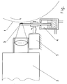
- FIG. 1 a printing form cylinder with an imaging device according to the invention shown at least schematically.
- a rotary printing press has at least one printing unit, which in turn at least is provided with a printing form cylinder 1.
- the printing form cylinder 1 itself, one encasing it Printing form sleeve (not shown) or a mounted on the printing form cylinder Pressure plate (not shown) are coated inside the machine with a coating (illustration) provided, e.g. as an intermediate carrier for the subsequent transfer to e.g. the substrate suitable.
- a laser writing head 2 the laser beams of which are perpendicular relative to the longitudinal axis the printing form cylinder 1 are aligned to this is in the immediate vicinity of Printing form cylinder 1 arranged.
- a transport disc 3 which has an upper section in the gap engages between the laser write head 2 and the printing cylinder 1. An opposite in this case Another / different section of the transport disk 3 simultaneously engages in a storage device 4 a.
- the transport disc 3 is driven by a separate motor 5 and rotates the disk 3 substantially parallel to a tangent to the cylinder.
- the transport disc 3 While the transport disc 3 each with a section due to its rotational movement moved through the reservoir 4, this constantly takes the image-bearing properties medium from the storage container 4 and transports it into the (imaging) Gap.
- the transport disc 3 is as close as possible to the surface of the printing form cylinder 1 along, but without touching it.
- the storage container 4 has on his upper free end or in its upper cover on a slot-shaped engagement through which the transport disk 3 engages in the storage container 4.
- the image-carrying medium can also e.g. ending of the imaging process can be refilled.
Landscapes
- Engineering & Computer Science (AREA)
- Mechanical Engineering (AREA)
- Manufacturing & Machinery (AREA)
- Physics & Mathematics (AREA)
- Optics & Photonics (AREA)
- Manufacture Or Reproduction Of Printing Formes (AREA)
- Electronic Switches (AREA)
Abstract
Description
- 1
- Druckformzylinder
- 2
- Laserschreibkopf
- 3
- Transportscheibe
- 4
- Vorratsbehälter
- 5
- Motor
Claims (20)
- Verfahren zum Herstellen einer Druckform für eine Rotationsdruckmaschine durch bildgemäß gesteuertes Beschichten einer Oberfläche eines sich drehenden Druckformzylinders mit einem bildtragende Eigenschaften aufweisenden Medium, das mittels eines oder mehrerer Laserstrahlen eines entlang des Druckformzylinders verfahrbaren Laserschreibkopfes auf die Oberfläche des Druckformzylinders aufgebracht wird,bei dem das bildtragende Medium von einem Transferelement transportiert wird,bei dem das Transferelement ein umlaufendes Transportmittel ist, das kontinuierlich durch einen Spalt, der zwischen der Oberfläche des Druckformzylinders und dem oder den Laserstrahlen gebildet ist, hindurch geführt wird, undbei dem das Transportmittel jeweils vor dem Durchlaufen des Spaltes durch eine Vorratseinrichtung hindurch geführt und während des Durchlaufens durch die Vorratseinrichtung mit dem bildtragende Eigenschaften aufweisenden Medium bestückt wird.
- Verfahren zum Herstellen einer Druckform gemäß Anspruch 1, bei dem das Transportmittel endlos ist und um eine Achse läuft und nach dem Passieren des Spaltes erneut durch die Vorratseinrichtung hindurch geführt und mit dem bildtragende Eigenschaften aufweisenden Medium bestückt wird.
- Verfahren zum Herstellen einer Druckform gemäß Anspruch 1 oder 2, bei dem das Transportmittel nach dem Passieren des Spaltes zunächst vollständig gereinigt und anschließend erneut mit dem bildtragende Eigenschaften aufweisenden Medium bestückt wird.
- Verfahren zum Herstellen einer Druckform gemäß Anspruch 1 oder 2, bei dem das Transportmittel nach dem Passieren des Spaltes mit bildtragende Eigenschaften aufweisendem Medium nachgerüstet wird.
- Verfahren zum Herstellen einer Druckform gemäß einem der Ansprüche 1 bis 4, bei dem das bildtragende Medium auf dem Transportmittel mittels elektrostatischer Haltekraft gehalten wird.
- Verfahren zum Herstellen einer Druckform gemäß einem der Ansprüche 1 bis 4, bei dem des bildtragende Medium auf dem Transportmittel mittels elektromagnetischer Haltekraft gehalten wird.
- Verfahren zum Herstellen einer Druckform gemäß einem der Ansprüche 1 bis 6, bei dem das bildtragende Medium mit Laserstrahlen beaufschlagt wird und kleinste Elemente des bildtragenden Mediums auf den Druckformzylinder übertragen werden.
- Verfahren nach einem der Ansprüche 1 bis 7, bei dem das bildtragende Medium auf den Druckformzylinder aufgeschmolzen oder aufgesintert wird.
- Verfahren nach einem der Ansprüche 1 bis 8, bei dem das bildtragende Medium innerhalb der Vorratseinrichtung auf das Transportmittel aufgesprüht wird.
- Verfahren nach einem der Ansprüche 1 bis 8, bei dem das bildtragende Medium innerhalb der Vorratseinrichtung auf das Transportmittel aufgespritzt wird.
- Verfahren nach einem der Ansprüche 1 bis 8, bei dem das bildtragende Medium innerhalb der Vorratseinrichtung auf das Transportmittel aufgestäubt wird.
- Verfahren nach einem der Ansprüche 1 bis 8, bei dem das Transportmittel innerhalb der Vorratseinrichtung in das bildtragende Medium eingetaucht und beschichtet wird.
- Vorrichtung zum Durchführen des Verfahrens gemäß Anspruch 1,mit einem Druckformzylinder (1),mit einem einen oder mehrere Laserstrahlen aussendenden Laserschreibkopf (2), der entlang des Druckformzylinders (1) verschiebbar angeordnet ist,mit einem umlaufenden Transferelement (3), mit welchem das bildtragende Eigenschaften aufweisende Medium transportierbar ist, wobei immer zumindest ein Abschnitt des Transferelements (3) zwischen Laserschreibkopf (2) und dem Druckformzylinder (1) eingreift, undmit einer Vorratseinrichtung (4), zum Bereitstellen des bildtragende Eigenschaften aufweisenden Mediums, in die das Transferelement (3) mit einem anderen Abschnitt eingreift.
- Vorrichtung nach Anspruch 13, bei der das als Transportmittel ausgebildete Transferelement ein endlos umlaufendes Transportband ist.
- Vorrichtung nach Anspruch 13, bei der das als Transportmittel ausgebildete Transferelement (3) eine einzelmotorisch antreibbare Transportscheibe ist.
- Vorrichtung nach Anspruch 15, bei der die Drehachse der Transportscheibe senkrecht zur Längsachse des Druckformzylinders (1) ausgerichtet ist.
- Vorrichtung nach Anspruch 15, bei der die Transportscheibe (3) Durchbrüche aufweist, in denen das bildtragende Medium gespeichert ist und die von Laserstrahlen durchdringbar sind.
- Vorrichtung nach einem der Ansprüche 13 bis 16, bei der das Transportmittel (3) aus laserdurchlässigem Material hergestellt ist.
- Vorrichtung nach einem der Ansprüche 13 bis 18, bei der der Laserschreibkopf (2) gemeinsam mit dem Transferelement (3) an einer entlang des Druckformzylinders (1) führenden Traverse verschiebbar angeordnet ist.
- Vorrichtung nach einer der Ansprüche 13 bis 19 , bei der der Laserschreibkopf (2) und das Transferelement (3) relativ zueinander in Längsrichtung des Druckformzylinders (1) verschiebbar sind.
Applications Claiming Priority (2)
| Application Number | Priority Date | Filing Date | Title |
|---|---|---|---|
| DE10235591 | 2002-08-03 | ||
| DE2002135591 DE10235591B4 (de) | 2002-08-03 | 2002-08-03 | Vorrichtung zum Bebildern der Oberfläche eines Druckformzylinders oder einer auf dem Druckformzylinder aufgespannten Druckform |
Publications (2)
| Publication Number | Publication Date |
|---|---|
| EP1386731A1 true EP1386731A1 (de) | 2004-02-04 |
| EP1386731B1 EP1386731B1 (de) | 2005-09-14 |
Family
ID=30010586
Family Applications (1)
| Application Number | Title | Priority Date | Filing Date |
|---|---|---|---|
| EP20030015245 Expired - Lifetime EP1386731B1 (de) | 2002-08-03 | 2003-07-05 | Verfahren und Vorrichtung zum Herstellen einer Druckform für eine Rotationsdruckmaschine |
Country Status (2)
| Country | Link |
|---|---|
| EP (1) | EP1386731B1 (de) |
| DE (2) | DE10235591B4 (de) |
Citations (3)
| Publication number | Priority date | Publication date | Assignee | Title |
|---|---|---|---|---|
| DE4430555C1 (de) * | 1994-08-27 | 1996-04-04 | Roland Man Druckmasch | Verfahren und Vorrichtung zur Herstellung einer Druckform |
| EP0836939A1 (de) * | 1995-06-20 | 1998-04-22 | MAXIMOVSKY, Sergei Nicolaevich | Druckmaschine |
| EP1188560A2 (de) * | 2000-09-15 | 2002-03-20 | MAN Roland Druckmaschinen AG | Thermotransferfolie mit reaktiver Polymermasse zur laserinduzierten Bilderzeugung |
Family Cites Families (3)
| Publication number | Priority date | Publication date | Assignee | Title |
|---|---|---|---|---|
| EP0138376B1 (de) * | 1983-09-19 | 1987-03-04 | Kabushiki Kaisha Toshiba | Verfahren und Vorrichtung zur Elektrophotographie |
| DE19544099A1 (de) * | 1995-11-27 | 1997-05-28 | Heidelberger Druckmasch Ag | Thermografische Druckeinrichtung |
| JP2002103657A (ja) * | 2000-09-29 | 2002-04-09 | Canon Inc | 記録装置 |
-
2002
- 2002-08-03 DE DE2002135591 patent/DE10235591B4/de not_active Expired - Fee Related
-
2003
- 2003-07-05 DE DE50301176T patent/DE50301176D1/de not_active Expired - Lifetime
- 2003-07-05 EP EP20030015245 patent/EP1386731B1/de not_active Expired - Lifetime
Patent Citations (3)
| Publication number | Priority date | Publication date | Assignee | Title |
|---|---|---|---|---|
| DE4430555C1 (de) * | 1994-08-27 | 1996-04-04 | Roland Man Druckmasch | Verfahren und Vorrichtung zur Herstellung einer Druckform |
| EP0836939A1 (de) * | 1995-06-20 | 1998-04-22 | MAXIMOVSKY, Sergei Nicolaevich | Druckmaschine |
| EP1188560A2 (de) * | 2000-09-15 | 2002-03-20 | MAN Roland Druckmaschinen AG | Thermotransferfolie mit reaktiver Polymermasse zur laserinduzierten Bilderzeugung |
Also Published As
| Publication number | Publication date |
|---|---|
| DE10235591A1 (de) | 2004-02-19 |
| EP1386731B1 (de) | 2005-09-14 |
| DE10235591B4 (de) | 2005-03-03 |
| DE50301176D1 (de) | 2005-10-20 |
Similar Documents
| Publication | Publication Date | Title |
|---|---|---|
| CH616766A5 (de) | ||
| EP0698488B1 (de) | Verfahren und Vorrichtung zur Herstellung einer Druckform | |
| DE102012022859A1 (de) | Aufbau eines 3D-Druckgerätes zur Herstellung von Bauteilen | |
| DE2727043B2 (de) | Vorrichtung zum Drucken von Markierungen auf Stahlplatten | |
| EP0297668A2 (de) | Verfahren zum Bedrucken plattenförmiger Informationsträger | |
| DE3546502C2 (de) | ||
| DE4112053C2 (de) | Verfahren zum Einstellen eines Streichspaltes in der Entwicklungsvorrichtung eines elektrofotografischen Druckers | |
| EP1989054A1 (de) | Träger mit einer materialschicht und verfahren zur herstellung eines trägers | |
| DE19811030B4 (de) | Verfahren und Vorrichtung zur Bereitstellung von Thermotransfermaterial zur Thermotransferbebilderung | |
| EP1386731B1 (de) | Verfahren und Vorrichtung zum Herstellen einer Druckform für eine Rotationsdruckmaschine | |
| DE4426124C2 (de) | Vorrichtung zum Transport von mit Randlochungen versehenen Aufzeichnungsträgern | |
| DE4140652A1 (de) | Vorrichtung zum beschichten eines substrates mit einer substanz | |
| DE2135110C3 (de) | Vorrichtung zum Bedrucken von Dragees | |
| EP2155499B1 (de) | Druckmaschine und druckverfahren hierfür | |
| DE2947623A1 (de) | Markierverfahren und -vorrichtung | |
| DE3639062A1 (de) | Schlagfreier drucker | |
| DE2904331C2 (de) | ||
| DE659415C (de) | Vorrichtung zum Aufbringen eines UEberzuges, insbesondere Farbueberzuges, auf wandernde Papier- oder aehnliche Werkstoffbahnen | |
| DE102008061638B4 (de) | Reinigungsanordnung für ein bewegtes zu reinigendes Element bei einem elektrografischen Druckgerät | |
| DE69800252T2 (de) | Siebabnahmevorrichtung für eine rotierende Druckmaschine mit Schutz gegen Tintenkontamination | |
| EP1386732B1 (de) | Verfahren und Vorrichtung zum Herstellen einer Druckform für eine Rotationsdruckmaschine | |
| DE19540164C1 (de) | Transportvorrichtung zum Transportieren von Endlos-Trägermaterial | |
| DE1597851B2 (de) | Vorrichtung fuer ein elektrofotografisches mehrfarbenverfahren | |
| DE2738546C2 (de) | Vorrichtung zur elektrophoretischen Flüssigentwicklung von Ladungsbildern | |
| DE102005003083A1 (de) | Druckmaschinen-Reinigungsvorrichtung |
Legal Events
| Date | Code | Title | Description |
|---|---|---|---|
| PUAI | Public reference made under article 153(3) epc to a published international application that has entered the european phase |
Free format text: ORIGINAL CODE: 0009012 |
|
| AK | Designated contracting states |
Kind code of ref document: A1 Designated state(s): AT BE BG CH CY CZ DE DK EE ES FI FR GB GR HU IE IT LI LU MC NL PT RO SE SI SK TR |
|
| AX | Request for extension of the european patent |
Extension state: AL LT LV MK |
|
| 17P | Request for examination filed |
Effective date: 20040106 |
|
| AKX | Designation fees paid |
Designated state(s): DE FR GB IT |
|
| GRAP | Despatch of communication of intention to grant a patent |
Free format text: ORIGINAL CODE: EPIDOSNIGR1 |
|
| GRAS | Grant fee paid |
Free format text: ORIGINAL CODE: EPIDOSNIGR3 |
|
| GRAA | (expected) grant |
Free format text: ORIGINAL CODE: 0009210 |
|
| AK | Designated contracting states |
Kind code of ref document: B1 Designated state(s): DE FR GB IT |
|
| REG | Reference to a national code |
Ref country code: GB Ref legal event code: FG4D Free format text: NOT ENGLISH |
|
| REF | Corresponds to: |
Ref document number: 50301176 Country of ref document: DE Date of ref document: 20051020 Kind code of ref document: P |
|
| GBT | Gb: translation of ep patent filed (gb section 77(6)(a)/1977) |
Effective date: 20060107 |
|
| ET | Fr: translation filed | ||
| PLBE | No opposition filed within time limit |
Free format text: ORIGINAL CODE: 0009261 |
|
| STAA | Information on the status of an ep patent application or granted ep patent |
Free format text: STATUS: NO OPPOSITION FILED WITHIN TIME LIMIT |
|
| 26N | No opposition filed |
Effective date: 20060615 |
|
| PGFP | Annual fee paid to national office [announced via postgrant information from national office to epo] |
Ref country code: DE Payment date: 20130801 Year of fee payment: 11 |
|
| PGFP | Annual fee paid to national office [announced via postgrant information from national office to epo] |
Ref country code: GB Payment date: 20130719 Year of fee payment: 11 Ref country code: FR Payment date: 20130722 Year of fee payment: 11 |
|
| PGFP | Annual fee paid to national office [announced via postgrant information from national office to epo] |
Ref country code: IT Payment date: 20130730 Year of fee payment: 11 |
|
| REG | Reference to a national code |
Ref country code: DE Ref legal event code: R119 Ref document number: 50301176 Country of ref document: DE |
|
| GBPC | Gb: european patent ceased through non-payment of renewal fee |
Effective date: 20140705 |
|
| REG | Reference to a national code |
Ref country code: FR Ref legal event code: ST Effective date: 20150331 |
|
| PG25 | Lapsed in a contracting state [announced via postgrant information from national office to epo] |
Ref country code: DE Free format text: LAPSE BECAUSE OF NON-PAYMENT OF DUE FEES Effective date: 20150203 Ref country code: IT Free format text: LAPSE BECAUSE OF NON-PAYMENT OF DUE FEES Effective date: 20140705 |
|
| REG | Reference to a national code |
Ref country code: DE Ref legal event code: R119 Ref document number: 50301176 Country of ref document: DE Effective date: 20150203 |
|
| PG25 | Lapsed in a contracting state [announced via postgrant information from national office to epo] |
Ref country code: FR Free format text: LAPSE BECAUSE OF NON-PAYMENT OF DUE FEES Effective date: 20140731 Ref country code: GB Free format text: LAPSE BECAUSE OF NON-PAYMENT OF DUE FEES Effective date: 20140705 |