EP1385585B1 - Fixation de ski - Google Patents
Fixation de ski Download PDFInfo
- Publication number
- EP1385585B1 EP1385585B1 EP02769198A EP02769198A EP1385585B1 EP 1385585 B1 EP1385585 B1 EP 1385585B1 EP 02769198 A EP02769198 A EP 02769198A EP 02769198 A EP02769198 A EP 02769198A EP 1385585 B1 EP1385585 B1 EP 1385585B1
- Authority
- EP
- European Patent Office
- Prior art keywords
- ski
- retaining element
- boot
- ski binding
- binding according
- Prior art date
- Legal status (The legal status is an assumption and is not a legal conclusion. Google has not performed a legal analysis and makes no representation as to the accuracy of the status listed.)
- Expired - Fee Related
Links
Images
Classifications
-
- A—HUMAN NECESSITIES
- A63—SPORTS; GAMES; AMUSEMENTS
- A63C—SKATES; SKIS; ROLLER SKATES; DESIGN OR LAYOUT OF COURTS, RINKS OR THE LIKE
- A63C9/00—Ski bindings
- A63C9/08—Ski bindings yieldable or self-releasing in the event of an accident, i.e. safety bindings
- A63C9/0807—Ski bindings yieldable or self-releasing in the event of an accident, i.e. safety bindings for both towing and downhill skiing
-
- A—HUMAN NECESSITIES
- A63—SPORTS; GAMES; AMUSEMENTS
- A63C—SKATES; SKIS; ROLLER SKATES; DESIGN OR LAYOUT OF COURTS, RINKS OR THE LIKE
- A63C7/00—Devices preventing skis from slipping back; Ski-stoppers or ski-brakes
- A63C7/10—Hinged stoppage blades attachable to the skis in such manner that these blades can be moved out of the operative position
- A63C7/1006—Ski-stoppers
- A63C7/1013—Ski-stoppers actuated by the boot
- A63C7/102—Ski-stoppers actuated by the boot articulated about one transverse axis
- A63C7/1026—Ski-stoppers actuated by the boot articulated about one transverse axis laterally retractable above the ski surface
-
- A—HUMAN NECESSITIES
- A63—SPORTS; GAMES; AMUSEMENTS
- A63C—SKATES; SKIS; ROLLER SKATES; DESIGN OR LAYOUT OF COURTS, RINKS OR THE LIKE
- A63C9/00—Ski bindings
- A63C9/02—Non-self-releasing bindings with swivel sole-plate or swivel parts, i.e. Ellefsen-type
-
- A—HUMAN NECESSITIES
- A63—SPORTS; GAMES; AMUSEMENTS
- A63C—SKATES; SKIS; ROLLER SKATES; DESIGN OR LAYOUT OF COURTS, RINKS OR THE LIKE
- A63C9/00—Ski bindings
- A63C9/20—Non-self-releasing bindings with special sole edge holders instead of toe-straps
-
- A—HUMAN NECESSITIES
- A63—SPORTS; GAMES; AMUSEMENTS
- A63C—SKATES; SKIS; ROLLER SKATES; DESIGN OR LAYOUT OF COURTS, RINKS OR THE LIKE
- A63C2201/00—Use of skates, skis, roller-skates, snowboards and courts
- A63C2201/06—Telemark
Definitions
- the invention relates to a ski binding according to the preamble of claim 1.
- ski binding according to the preamble of claim 1 is known.
- This ski binding has in an advantageous embodiment, on the underside of the shoe front sole attacking clamping element, which is in particular designed as a flexurally elastic part in the form of a spring band or leaf.
- This ski binding provides good guiding and power transmission properties, but there is still room for improvement, especially in terms of safety features as well as a simple and low-power operation.
- the invention is therefore the object of the development of a generic ski binding with the aim of creating a easy-to-operate safety ski binding for cross-country skiing, touring skiing or downhill skiing in telemark style.
- a resilient design of the first holding element forming clamp advantageously makes it possible to unscrew the ski boot front tip with inadmissibly high torsional load between ski and ski boot and thus realized in a very simple manner a very important during departure safety aspect of the proposed ski binding.
- the invention includes the fundamental idea, constructively simple and at the same time stable perform as a clip, the front support member which engages around the sole of the ski boot near the toe from both sides. It further includes the idea to assign an elastic pressure element to the requirement of an anatomically and physiologically advantageous movement sequence while running in this holding element, which presses the sole against the retaining clip, but elastically yielding when lifting the heel under the toe.
- the holding element is designed as a cross-sectionally substantially U-shaped retaining clip made of metal (especially steel) or a high-strength plastic, wherein the ends of the legs of the "U" are angled inwards and the engaging portions with the Make up the top of the ski boot front sole.
- This retaining clip is facing with its base to the ski and attached to this or a binding base plate.
- the pressure element is preferably designed as a position of use under the sole of the ski boot lying, even at low temperatures permanently elastomeric block.
- the elastomer block is expediently before or partly within the retaining clip. In particular, it may have a slightly sloping sloping end towards the end of the ski and / or a slightly convex curved surface in the longitudinal section plane.
- the tensioning device comprises in a preferred embodiment, a flexible in a longitudinal sectional plane of the ski binding biegeeleasticians connecting part, in particular a flexible plastic plate, which connects the front and rear support member at least indirectly, wherein in addition to the bending elasticity of the connecting part itself by additional means a certain, spring-loaded mobility in SkiLlindsraum is realized.
- the planar connecting part is guided laterally relative to the ski, in particular by the side walls of a binding housing fastened to the ski, which partially surround the side edges of the connecting part, at least in the front region.
- a spring means for biasing the rear retaining element in the locking position with the ski boot - in a further preferred embodiment specifically with the front sole - provided.
- a front spring means for biasing the first locking element in engagement position with the second locking element is provided between the front and rear retaining element, and on the rear retaining element is a rear spring means for biasing the rear retaining element in engagement position with the shoe front sole (or the paragraph Trailing edge) provided.
- the two spring means cooperate during locking and unlocking of the binding, and the spring force of the rear spring means is greater than that of the front spring means predetermined.
- a release of the engagement state between the first and second locking element causes a slight return of the clamping device with the rear retaining element mounted therein under the action of the rear spring means and against the (weaker) effect of the front spring means.
- the lock between the rear support member and the corresponding engagement portion of the ski boot sole is released (“release") and the ski boot can be swung out of the binding.
- the rear spring device relaxes, and then the front spring device can exert its effect and return the engagement element to the longitudinal position, which allows re-engagement with the second locking element.
- the binding is then back in initial position ("step-in").
- the flat connecting part - accompanying change in length spring means are preferably provided on the rear support member.
- this function takes over the above-mentioned rear spring device, which supplies the rest of the spring preload for locking the rear retaining element.
- adjusting means for length adjustment of the binding are provided on the rear holding element - in an alternative embodiment also in the region of the front holding element, which expediently comprise a slider arranged in a longitudinal guide and there (for example with a locking screw).
- the front spring device has a helical spring with a long stroke which is supported at one end against a binding mounting plate and connected to the other end with the (second) unlocking device, used as a compression spring element.
- This compression spring element biases the second locking element in the engaged position with the first locking element. This engagement is released (as mentioned elsewhere) by exerting pressure on the first locking element from above, so that the skier can get out of the binding.
- a pivot lever which - can be pivoted - in particular by the Torsionsfederelement - in a closed position and by pressure on a suitably arranged and shaped actuating portion in the open position.
- the planar connecting element is designed as a support plate for the ski boot front sole, which is expediently roughly contoured on the underside to avoid malfunction by accumulated snow.
- the planar connecting element with an attacking on the ski boot front sole rear retaining element behind this also one - expediently also roughly contoured - support element for the shoe heel is provided.
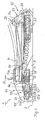
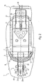
- Fig. 1 and 2 show a ski binding 1 according to a first embodiment of the invention in the mounted on a (not shown) ski state, one has to imagine on the left side of the figure, the ski tip and on the right side of the ski end.
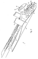
- Fig. 3 shows the essential components of the front part of the ski binding 1 again in a spatial representation.
- the ski surface 3 is shown as a solid line, and it is shown the front lower part of a ski boot 5 to a fully lowered position and the other with a slightly raised paragraph.
- the ski boot 5 has a front sole 7 with a circumferentially protruding sole edge 7a and a rear sole end 7b, which are in engagement with essential functional elements of the ski binding 1 (see below).
- the ski binding 1 comprises as essential functional units a mounting plate 9, a front holding element 11 with associated elastic pressure element 13, a rear holding device 15, a front holding element 11 with the rear holding device 15 connecting flexible plastic plate 17 and arranged in front of the front holding element unlocking 19th
- the front retaining element 11 is formed as a resilient steel retaining clip with a substantially U-shaped cross section, wherein the legs of the "U" inwardly directed bends 11a have, with which the retaining clip 11 from both sides of the sole edge 7a of the ski boot front sole embraces. How best in Fig. 2 and 3 can be seen, the retaining clip 11 is slightly widened in adaptation to the shape of the ski boot front sole to the rear. Their resilient design allows the action of an inadmissibly high torsional force between the ski boot and ski a resilient expansion, which is a unscrewing the front sole 7 from the retaining clip 11 and thus a release of the ski boot 5 from the binding 1 and thus allows the ski.
- the elastic pressure element 13 arranged in the embodiment shown directly in front of the retaining clip 11 and designed as a solid elastomer block whose upper side is slightly convex and slightly sloping towards the rear, makes surface contact with the underside of the front sole 7, presses the upper side of the sole edge 7a against the latter Bottom of the folds 11a and thus creates a frictional resistance against rotation of the ski boot 5 about an axis perpendicular to the ski surface. This ensures that a rotation of the ski boot is only possible with larger lateral forces and unscrewing the ski boot 5 from the binding only at dangerously high lateral forces.
- the elastomer block 13 thus provides in this regard for reasonable guiding properties of the binding in combination with a safety trip function.
- the elastomer block 13 opposes an increase in the heel of the ski boot 5 an elastic resistance at the top of the front sole 7 and thus generates the biodynamically desirable restoring force in such a lifting.
- the rear holding device 15 is - as it does not concern the core of the invention - described below only in broad terms. It comprises as a rear retaining element a spring-loaded pivoting lever 21, which is connected via a pair of rollers 23 in engagement with the rear sole end 7b. By a pivoting movement follows the (in Fig. 1 pivoting lever 21 shown in two pivoting positions, to a certain extent lifting the heel of the ski boot 5, without the engagement between the pair of rollers 23 and the rear sole end 7b is canceled.
- a rear one Spring means 25 embedded in a retainer housing 27 attracts the rear retainer 21 against the rear sole end 7b.
- An adjusting screw 29 is used to adjust the rear holding device 15th
- the unlocking device 19 for opening the binding comprises substantially designed as torsionsfederbelastete pivot lever first locking element 31 and designed as a spring-loaded slider 33 second locking element. Both parts 31, 33 are approximately U-shaped in cross-section and have at the front end in each case a fold 31a, 33a as an engagement portion for mutual engagement.
- the first locking element forming pivot lever 31 is pivotable about an axis of rotation 35 which is mounted in a U-shaped holder 37. To the rotation axis 35 acting as a torsion spring coil spring 39 is wound, which biases the pivot lever 31 in the engaged position with the slider 33.
- a torsion spring coil spring 39 acting as a torsion spring coil spring 39 is wound, which biases the pivot lever 31 in the engaged position with the slider 33.
- the second locking element (slider) 33 has in addition to the aforementioned first, upwardly facing edge 33a, a second, downwardly facing edge 33b, which projects into a front spring device (coil spring) 47. This biases the slider 33 forward - ie in the engaged position with the pivot lever 31 - before.
- the slider 33 passes through the elastomeric block 13 in which two (not separately designated) slots are provided for this purpose, and the retaining clip 11 and is connected at its end via a fastening and pivot axis 49 with the plastic plate 17.
- this is flexurally elastic, but not stretchable, whereby a total of a tensile connection between the front end of the slider 33 (the fold 33a) and the rear holding device 15 is formed.
- an elasticity of the binding in the longitudinal direction for flexion compensation is realized solely by the torsion spring loading of the rear retaining element 21.
Landscapes
- Footwear And Its Accessory, Manufacturing Method And Apparatuses (AREA)
Abstract
Claims (15)
- Fixation de ski (1), en particulier fixation pour randonnée, télémark ou ski de fond, avec- un élément de retenue avant, associé à l'extrémité avant de la semelle (7a) d'une chaussure de ski (5),- un élément de retenue (21) arrière, réalisé pour la prise d'une arête (7b) sur la semelle avant de la chaussure ou sur le talon de la chaussure de ski et- un dispositif de serrage (17 ; 25 ; 47) reliant les éléments de retenue avant et arrière entre eux, lequel permet un verrouillage des éléments de retenue avant et arrière avec la chaussure de ski et en particulier à l'état verrouillé, un levage du talon de la chaussure de ski par rapport au ski,caractérisée en ce que
l'élément de retenue avant entoure des deux côtés comme une bride de fixation, en particulier en élasticité latérale, la semelle de la chaussure de ski près du bout de la chaussure et à l'élément de retenue avant est associé un élément (13) élastique, contre l'action duquel l'extrémité avant de la semelle peut être déplacée vers le bas lors du levage simultané du talon de la chaussure. - Fixation de ski selon la revendication 1,
caractérisée en ce que
l'élément de retenue (11) est réalisé comme un étrier de retenue de section essentiellement en forme de U, monté avec sa base sur le ski, particulièrement en métal à élasticité de ressort ou en matière plastique très résistante avec des extrémités (11a) repliées vers l'intérieur des branches et
l'élément (13) élastique est réalisé comme un bloc en élastomère se trouvant en position d'usage sous la semelle de la chaussure de ski et dans et/ou devant l'étrier de retenue. - Fixation de ski selon la revendication 1 ou 2,
caractérisée en ce qu'
au dispositif de serrage est associé au moins un dispositif de déverrouillage (19) sollicité par ressort pour la suppression du verrouillage entre la fixation de ski (1) et la chaussure de ski (5) lors de l'action manuelle sur un premier élément de verrouillage (31) agissant essentiellement par complémentarité de forme. - Fixation de ski selon l'une quelconque des revendications précédentes,
caractérisée en ce que
le dispositif de serrage présente une partie de liaison (17) plane, élastique en flexion dans un plan de coupe longitudinale de la fixation de ski pour la liaison au moins indirecte, à élasticité de ressort et bloquée en rotation de l'élément de retenue (11) avant avec l'élément de retenue (21) arrière. - Fixation de ski selon la revendication 4,
caractérisée en ce que
la partie de liaison (17) plane est guidée latéralement par rapport au ski, en particulier par les parois latérales entourant les arêtes latérales de la partie de liaison d'un boîtier de fixation (45) fixé sur le ski. - Fixation de ski selon l'une quelconque des revendications précédentes,
caractérisée en ce que
dans la zone de l'élément de retenue (11) avant sont prévus un second élément de verrouillage (33) coopérant avec le premier élément de verrouillage (31) ainsi qu'un dispositif à ressort (47) avant pour la précontrainte du premier élément de verrouillage en position d'engagement avec le second élément de verrouillage et sur l'élément de retenue (21) arrière est prévu un dispositif à ressort arrière coopérant avec le dispositif à ressort (47) avant pour la précontrainte de l'élément de retenue arrière en position d'engagement avec la semelle avant de la chaussure (7) ou le talon, la force de ressort du dispositif à ressort arrière étant supérieure à celle du dispositif à ressort avant. - Fixation de ski selon l'une quelconque des revendications précédentes,
caractérisée en ce que
l'élément de retenue (21) arrière est monté de manière pivotante autour d'un axe de pivotement (49) essentiellement parallèle à la surface du ski (3) et perpendiculaire à l'axe longitudinal du ski sur le dispositif de serrage. - Fixation de ski selon la revendication 7,
caractérisée en ce que
l'axe de pivotement (49) est disposé dans la zone de l'élément de retenue (11) avant, en particulier dans la zone au-dessous de la semelle avant (7) de la chaussure de ski. - Fixation de ski selon l'une quelconque des revendications précédentes,
caractérisée en ce que
l'élément de retenue (21) arrière est réalisé de manière actionnable par une saillie (7b) sur la semelle avant de la chaussure de ski (7) ou l'arête arrière du talon lors de la mise de la chaussure de ski (5). - Fixation de ski selon la revendication 6 ou 7,
caractérisée en ce que
l'élément de retenue (21) est relié comme un levier au dispositif à ressort (25) arrière de sorte que l'actionnement de l'élément de retenue soit effectué par la mise de la chaussure de ski (5) derrière la saillie (7b) sur la semelle avant de la chaussure de ski (7) dans le sens inverse de la précontrainte de ressort générée par le dispositif à ressort arrière. - Fixation de ski selon l'une quelconque des revendications 6 à 10,
caractérisée en ce que
des moyens de ressort (25) sont prévus sur l'élément de retenue (21) arrière pour la compensation de flexion, lesquels sont formés en particulier par le dispositif à ressort arrière. - Fixation de ski selon l'une quelconque des revendications 6 à 11,
caractérisée en ce que
le dispositif à ressort (47) avant présente un ressort de pression appuyé sur une extrémité contre une plaque de montage de fixation (9) et précontraignant avec l'autre extrémité le second élément de verrouillage (33) vers l'avant et ainsi en position d'engagement et ainsi avec le premier élément de verrouillage (31), en particulier un ressort à boudin en acier. - Fixation de ski selon l'une quelconque des revendications 6 à 12,
caractérisée en ce que
le premier élément de verrouillage (31) est réalisé comme un levier pivotant autour d'un axe de pivotement horizontal et orienté perpendiculairement à l'axe longitudinal du ski dans le sens inverse de la force de précontrainte d'un ressort de torsion (39) coaxial à l'axe de pivotement par actionnement manuel. - Fixation de ski selon l'une quelconque des revendications 6 à 13,
caractérisée en ce que
le second élément de verrouillage (33) est réalisé comme un coulisseau relié à pivotement à l'extrémité avant de la partie de liaison (17) plane sur un axe de pivotement (49) au niveau de son extrémité arrière, dont l'extrémité avant n'est pas en engagement au repos ainsi que dans la position d'utilisation de la fixation de ski mais pendant l'actionnement manuel de déclenchement, avec le premier élément de verrouillage (31). - Fixation de ski selon l'une quelconque des revendications précédentes,
caractérisée en ce que
sur l'élément de retenue (21) arrière sont prévus des moyens de réglage (29) pour le réglage longitudinal de la fixation de ski, en particulier avec un coulisseau pouvant être bloqué dans un guidage longitudinal.
Priority Applications (1)
| Application Number | Priority Date | Filing Date | Title |
|---|---|---|---|
| EP07006974A EP1795236B1 (fr) | 2001-05-08 | 2002-05-07 | Fixation de ski |
Applications Claiming Priority (5)
| Application Number | Priority Date | Filing Date | Title |
|---|---|---|---|
| DE10122187 | 2001-05-08 | ||
| DE10122187 | 2001-05-08 | ||
| DE10124893A DE10124893A1 (de) | 2001-05-08 | 2001-05-22 | Skibindung |
| DE10124893 | 2001-05-22 | ||
| PCT/IB2002/001644 WO2002089931A1 (fr) | 2001-05-08 | 2002-05-07 | Fixation de ski |
Related Child Applications (1)
| Application Number | Title | Priority Date | Filing Date |
|---|---|---|---|
| EP07006974A Division EP1795236B1 (fr) | 2001-05-08 | 2002-05-07 | Fixation de ski |
Publications (2)
| Publication Number | Publication Date |
|---|---|
| EP1385585A1 EP1385585A1 (fr) | 2004-02-04 |
| EP1385585B1 true EP1385585B1 (fr) | 2009-03-25 |
Family
ID=26009246
Family Applications (1)
| Application Number | Title | Priority Date | Filing Date |
|---|---|---|---|
| EP02769198A Expired - Fee Related EP1385585B1 (fr) | 2001-05-08 | 2002-05-07 | Fixation de ski |
Country Status (4)
| Country | Link |
|---|---|
| US (2) | US7207591B2 (fr) |
| EP (1) | EP1385585B1 (fr) |
| NO (1) | NO328592B1 (fr) |
| WO (1) | WO2002089931A1 (fr) |
Families Citing this family (19)
| Publication number | Priority date | Publication date | Assignee | Title |
|---|---|---|---|---|
| WO2003101555A1 (fr) * | 2002-06-04 | 2003-12-11 | Rottefella As | Fixation de ski, notamment fixation de ski de randonnee, de telemark ou de fond |
| DE10254471A1 (de) | 2002-11-21 | 2004-06-03 | Madsus A/S | Ski mit Bindungs-Montagehilfe, Verfahren zur Herstellung eines solchen Ski sowie entsprechende Montagehilfe |
| DE102004024881A1 (de) * | 2004-05-19 | 2005-07-14 | Rottefella As | Langlauf- oder Telemarkbindung |
| AT502930B1 (de) * | 2005-01-04 | 2011-02-15 | Atomic Austria Gmbh | Verbindungsvorrichtung zwischen einem schuh und einem brettartigen sportgerät, insbesondere schibindung |
| WO2006072812A1 (fr) * | 2005-01-10 | 2006-07-13 | Rottefella As | Ski ou appareils similaires permettant de glisser sur la neige, pourvus d'un systeme d'aide au montage de la fixation |
| WO2006085131A1 (fr) * | 2005-02-11 | 2006-08-17 | Rottefella As | Semelle exterieure pour chaussure de ski de fond ou de telemark, ou chaussure de telemark dotee de cette semelle exterieure |
| US7681905B2 (en) * | 2007-02-01 | 2010-03-23 | Rottefella As | Ski binding, especially telemark binding |
| EP2111900B1 (fr) * | 2008-04-25 | 2011-12-14 | Rottefella AS | Cartouche de ressort pour fixation de ski |
| AT11239U1 (de) * | 2008-11-03 | 2010-07-15 | Atomic Austria Gmbh | Schibindung mit einer positionier- und fixiervorrichtung für deren backenkörper |
| FR2946545B1 (fr) * | 2009-06-16 | 2011-07-15 | Salomon Sas | Fixation pour ski et ski associe |
| NO20101289A1 (no) * | 2010-09-15 | 2012-03-16 | Rottefella As | Langrennsbinding, samt fremgangsmate for sammenstilling av nevnte langrennsbinding |
| NO334059B1 (no) * | 2011-10-14 | 2013-12-02 | Rottefella As | Skibinding |
| NO334063B1 (no) * | 2012-01-13 | 2013-12-02 | Rottefella As | Skibrems |
| US8833793B2 (en) | 2012-06-15 | 2014-09-16 | Fritschi Ag-Swiss Bindings | Skibindung |
| NO336669B1 (no) * | 2012-11-19 | 2015-10-19 | Rottefella As | Skibinding |
| FR2999090A1 (fr) * | 2012-12-10 | 2014-06-13 | Rossignol Sa | Dispositif de freinage pour ski de randonnee |
| DE102013224579B4 (de) | 2013-11-29 | 2022-01-20 | Salewa Sport Ag | Gleitbrettbindung mit vorderer Halteeinrichtung und Bremseinrichtung |
| DE102019108350A1 (de) * | 2019-03-29 | 2020-10-01 | Marker Deutschland Gmbh | Bremsvorrichtung |
| US11110338B1 (en) * | 2020-07-14 | 2021-09-07 | Thomas Alan Miller | Ski binding with heelless telemark coupling |
Citations (1)
| Publication number | Priority date | Publication date | Assignee | Title |
|---|---|---|---|---|
| EP0806977B1 (fr) * | 1995-02-02 | 1999-07-07 | Rottefella A/S | Combinaison d'une fixation de ski et d"une chaussure adaptee a ladite fixation |
Family Cites Families (29)
| Publication number | Priority date | Publication date | Assignee | Title |
|---|---|---|---|---|
| US2072477A (en) * | 1935-10-23 | 1937-03-02 | David H Dodd | Ski binding |
| US2576639A (en) * | 1948-01-30 | 1951-11-27 | Purvis Robert | Ski harness |
| CH468838A (de) * | 1965-11-11 | 1969-02-28 | Suhner Willy | In Verbindung mit einem Skibindungsvorderteil durch Hineintreten sich von selbst schliessender, kabelloser Ski-Sicherheitsbindungsfersenteil |
| CH456418A (de) * | 1965-12-07 | 1968-07-31 | Attenhofer Ag A | Montagebasis für einen Teil einer Skibindung |
| US3447812A (en) * | 1967-07-26 | 1969-06-03 | Koji Kato | Device for binding the heel part of a ski shoe |
| AT347837B (de) * | 1975-09-23 | 1979-01-10 | Smolka & Co Wiener Metall | Skibremse |
| AT343522B (de) * | 1975-12-24 | 1978-06-12 | Hausleithner Andreas | Kabellose sicherheitsschibindung |
| US4196921A (en) * | 1976-10-12 | 1980-04-08 | Sherwin William C | Cross-country ski boot restraining apparatus |
| US4322090A (en) * | 1980-02-13 | 1982-03-30 | Loughney Charles E | Ski mountaineering binding |
| DE3048175A1 (de) * | 1980-12-19 | 1982-07-22 | Heinrich Wunder GmbH & Co KG, 8060 Dachau | Tourenbindung mit skistopper |
| DE3370444D1 (en) * | 1982-01-27 | 1987-04-30 | Haldemann Ag | Safety ski binding |
| DE3412073C1 (de) | 1984-03-31 | 1989-08-10 | Heinz 8391 Tiefenbach Beck | Langlauf-Sicherheitsskibindung |
| US4871186A (en) * | 1987-02-20 | 1989-10-03 | Klosterman James E | Simplified adjustable ski binding structure |
| IT1225976B (it) * | 1988-09-19 | 1990-12-10 | Olivieri Icaro & C | Attacco integrato per sci da fondo. |
| US4887833A (en) * | 1988-09-26 | 1989-12-19 | Bailey Mark R | Touring ski binding |
| US5362088A (en) * | 1989-02-21 | 1994-11-08 | Varpat Patentverwertungs Ag | Safety ski binding having toe and heel forked clamp assemblies |
| DE3929352A1 (de) * | 1989-09-04 | 1991-03-14 | Witco As | Seitliche fuehrungsvorrichtung eines skischuhs |
| AT396068B (de) * | 1990-03-30 | 1993-05-25 | Tyrolia Freizeitgeraete | Skibindung fuer einen langlauf- oder tourenski |
| DE4010929A1 (de) * | 1990-04-04 | 1991-10-10 | Walter Dekanovsky | Langlaufskibindung |
| FR2738158B1 (fr) | 1995-09-06 | 1997-10-17 | Salomon Sa | Dispositif de fixation |
| FR2741543A1 (fr) | 1995-11-27 | 1997-05-30 | Bibollet Jean Claude | Fixations pour ski de fond |
| NO306540B1 (no) * | 1997-06-20 | 1999-11-22 | Linken Binding | Skibinding |
| US6308979B1 (en) * | 1998-01-29 | 2001-10-30 | James A. Ludlow | Releasable cross country ski binding |
| DE19809729A1 (de) * | 1998-03-06 | 1999-09-09 | Rottefella As | Langlauf- oder Tourenskibindung |
| FR2779659B1 (fr) | 1998-06-16 | 2000-09-01 | Christophe Oddoux | Dispositif d'articulation complementaire de fixation de ski ou de raquette |
| US6644683B1 (en) * | 1998-07-22 | 2003-11-11 | Rottefella As | Ski binding, especially for cross-country skis |
| DE10031775A1 (de) | 2000-03-07 | 2001-10-11 | Rottefella As Klokkarstua | Skibindung |
| WO2001066204A1 (fr) | 2000-03-07 | 2001-09-13 | Rottefella As | Fixation de ski |
| WO2001093963A1 (fr) | 2000-06-08 | 2001-12-13 | Rottefella As | Ensemble constitue d'une fixation de ski et d'une chaussure de ski |
-
2002
- 2002-05-07 US US10/477,052 patent/US7207591B2/en not_active Expired - Fee Related
- 2002-05-07 EP EP02769198A patent/EP1385585B1/fr not_active Expired - Fee Related
- 2002-05-07 WO PCT/IB2002/001644 patent/WO2002089931A1/fr active Application Filing
-
2003
- 2003-11-04 NO NO20034921A patent/NO328592B1/no not_active IP Right Cessation
-
2006
- 2006-12-01 US US11/633,109 patent/US7422227B2/en not_active Expired - Fee Related
Patent Citations (1)
| Publication number | Priority date | Publication date | Assignee | Title |
|---|---|---|---|---|
| EP0806977B1 (fr) * | 1995-02-02 | 1999-07-07 | Rottefella A/S | Combinaison d'une fixation de ski et d"une chaussure adaptee a ladite fixation |
Also Published As
| Publication number | Publication date |
|---|---|
| NO328592B1 (no) | 2010-03-29 |
| EP1385585A1 (fr) | 2004-02-04 |
| US7422227B2 (en) | 2008-09-09 |
| US20070126204A1 (en) | 2007-06-07 |
| US20040207177A1 (en) | 2004-10-21 |
| NO20034921D0 (no) | 2003-11-04 |
| US7207591B2 (en) | 2007-04-24 |
| WO2002089931A1 (fr) | 2002-11-14 |
Similar Documents
| Publication | Publication Date | Title |
|---|---|---|
| EP1385585B1 (fr) | Fixation de ski | |
| EP1292369B1 (fr) | Ensemble constitue d'une fixation de ski et d'une chaussure de ski | |
| EP0551899B1 (fr) | Fixation de ski de fond ou de ski de randonnée pour des chaussures de ski de fond | |
| EP0265459B1 (fr) | Fixation de ski de fond | |
| AT401710B (de) | Skischuh | |
| EP0351881A2 (fr) | Fixation recouplée au réglage d'une tige de chaussure de ski | |
| DE3201319A1 (de) | Skibindungsbacken | |
| EP1261402A1 (fr) | Fixation de ski | |
| DE2756897A1 (de) | Sicherheitsskibindung | |
| EP1509288B1 (fr) | Fixation de ski, notamment fixation de ski de randonnee, de telemark ou de fond | |
| EP0424479B1 (fr) | Fixation pour skis de fond ou de randonnee | |
| DE3405861C2 (de) | Langlauf- bzw. Wanderbindung | |
| EP0058848A1 (fr) | Baton de ski ajustable en longueur | |
| EP1795236A1 (fr) | Fixation de ski | |
| DE19703955A1 (de) | Tourenbindung | |
| DE2608073A1 (de) | Fersenniederhalter fuer sicherheits- skibindungen | |
| DE10319675A1 (de) | Skibindung, insbesondere Touren-, Telemark- oder Langlaufbindung | |
| DE4424737C1 (de) | Snowboardbindung | |
| WO1996039233A1 (fr) | Dispositif pour fixation de ski de fond, en particulier pour la pratique du patinage | |
| DE2528578A1 (de) | Sicherheitsbindung fuer skischuhe | |
| EP0072903B1 (fr) | Talonnière pour fixation de ski | |
| DE2650678A1 (de) | Langlaufbindung | |
| DE3240183A1 (de) | Backen einer sicherheitsskibindung | |
| DE102020200181A1 (de) | Ferseneinheit mit steighilfe für eine tourenbindung | |
| EP1468710B1 (fr) | Fixation de ski, en particulier pour ski de randonnee, telemark ou ski de fond |
Legal Events
| Date | Code | Title | Description |
|---|---|---|---|
| PUAI | Public reference made under article 153(3) epc to a published international application that has entered the european phase |
Free format text: ORIGINAL CODE: 0009012 |
|
| 17P | Request for examination filed |
Effective date: 20031031 |
|
| AK | Designated contracting states |
Kind code of ref document: A1 Designated state(s): AT BE CH CY DE DK ES FI FR GB GR IE IT LI LU MC NL PT SE TR |
|
| AX | Request for extension of the european patent |
Extension state: AL LT LV MK RO SI |
|
| 17Q | First examination report despatched |
Effective date: 20070103 |
|
| RBV | Designated contracting states (corrected) |
Designated state(s): DE FR |
|
| RIN1 | Information on inventor provided before grant (corrected) |
Inventor name: RIEDEL, TILO Inventor name: HAUGLIN, BERNT-OTTO |
|
| GRAP | Despatch of communication of intention to grant a patent |
Free format text: ORIGINAL CODE: EPIDOSNIGR1 |
|
| GRAS | Grant fee paid |
Free format text: ORIGINAL CODE: EPIDOSNIGR3 |
|
| GRAA | (expected) grant |
Free format text: ORIGINAL CODE: 0009210 |
|
| AK | Designated contracting states |
Kind code of ref document: B1 Designated state(s): DE FR |
|
| REF | Corresponds to: |
Ref document number: 50213389 Country of ref document: DE Date of ref document: 20090507 Kind code of ref document: P |
|
| PLBE | No opposition filed within time limit |
Free format text: ORIGINAL CODE: 0009261 |
|
| STAA | Information on the status of an ep patent application or granted ep patent |
Free format text: STATUS: NO OPPOSITION FILED WITHIN TIME LIMIT |
|
| 26N | No opposition filed |
Effective date: 20091229 |
|
| REG | Reference to a national code |
Ref country code: FR Ref legal event code: PLFP Year of fee payment: 15 |
|
| PGFP | Annual fee paid to national office [announced via postgrant information from national office to epo] |
Ref country code: DE Payment date: 20160504 Year of fee payment: 15 |
|
| PGFP | Annual fee paid to national office [announced via postgrant information from national office to epo] |
Ref country code: FR Payment date: 20160412 Year of fee payment: 15 |
|
| REG | Reference to a national code |
Ref country code: DE Ref legal event code: R119 Ref document number: 50213389 Country of ref document: DE |
|
| REG | Reference to a national code |
Ref country code: FR Ref legal event code: ST Effective date: 20180131 |
|
| PG25 | Lapsed in a contracting state [announced via postgrant information from national office to epo] |
Ref country code: DE Free format text: LAPSE BECAUSE OF NON-PAYMENT OF DUE FEES Effective date: 20171201 |
|
| PG25 | Lapsed in a contracting state [announced via postgrant information from national office to epo] |
Ref country code: FR Free format text: LAPSE BECAUSE OF NON-PAYMENT OF DUE FEES Effective date: 20170531 |