EP1385184A1 - Vorrichtung zum Erwärmen von Flüssigkeiten - Google Patents
Vorrichtung zum Erwärmen von Flüssigkeiten Download PDFInfo
- Publication number
- EP1385184A1 EP1385184A1 EP03015235A EP03015235A EP1385184A1 EP 1385184 A1 EP1385184 A1 EP 1385184A1 EP 03015235 A EP03015235 A EP 03015235A EP 03015235 A EP03015235 A EP 03015235A EP 1385184 A1 EP1385184 A1 EP 1385184A1
- Authority
- EP
- European Patent Office
- Prior art keywords
- base station
- container
- switching
- control element
- liquid container
- Prior art date
- Legal status (The legal status is an assumption and is not a legal conclusion. Google has not performed a legal analysis and makes no representation as to the accuracy of the status listed.)
- Granted
Links
- 239000007788 liquid Substances 0.000 title claims description 71
- 238000010438 heat treatment Methods 0.000 title claims description 28
- 230000013011 mating Effects 0.000 claims description 6
- XLYOFNOQVPJJNP-UHFFFAOYSA-N water Substances O XLYOFNOQVPJJNP-UHFFFAOYSA-N 0.000 abstract description 4
- 238000007654 immersion Methods 0.000 description 7
- 239000012530 fluid Substances 0.000 description 2
- 238000000034 method Methods 0.000 description 2
- 230000036316 preload Effects 0.000 description 2
- 238000009835 boiling Methods 0.000 description 1
- 230000008878 coupling Effects 0.000 description 1
- 238000010168 coupling process Methods 0.000 description 1
- 238000005859 coupling reaction Methods 0.000 description 1
- 238000005485 electric heating Methods 0.000 description 1
- 238000000926 separation method Methods 0.000 description 1
Images


Classifications
-
- A—HUMAN NECESSITIES
- A47—FURNITURE; DOMESTIC ARTICLES OR APPLIANCES; COFFEE MILLS; SPICE MILLS; SUCTION CLEANERS IN GENERAL
- A47J—KITCHEN EQUIPMENT; COFFEE MILLS; SPICE MILLS; APPARATUS FOR MAKING BEVERAGES
- A47J27/00—Cooking-vessels
- A47J27/21—Water-boiling vessels, e.g. kettles
- A47J27/21008—Water-boiling vessels, e.g. kettles electrically heated
- A47J27/2105—Water-boiling vessels, e.g. kettles electrically heated of the cordless type, i.e. whereby the water vessel can be plugged into an electrically-powered base element
-
- A—HUMAN NECESSITIES
- A47—FURNITURE; DOMESTIC ARTICLES OR APPLIANCES; COFFEE MILLS; SPICE MILLS; SUCTION CLEANERS IN GENERAL
- A47J—KITCHEN EQUIPMENT; COFFEE MILLS; SPICE MILLS; APPARATUS FOR MAKING BEVERAGES
- A47J27/00—Cooking-vessels
- A47J27/21—Water-boiling vessels, e.g. kettles
- A47J27/21008—Water-boiling vessels, e.g. kettles electrically heated
- A47J27/21058—Control devices to avoid overheating, i.e. "dry" boiling, or to detect boiling of the water
- A47J27/21066—Details concerning the mounting thereof in or on the water boiling vessel
-
- A—HUMAN NECESSITIES
- A47—FURNITURE; DOMESTIC ARTICLES OR APPLIANCES; COFFEE MILLS; SPICE MILLS; SUCTION CLEANERS IN GENERAL
- A47J—KITCHEN EQUIPMENT; COFFEE MILLS; SPICE MILLS; APPARATUS FOR MAKING BEVERAGES
- A47J27/00—Cooking-vessels
- A47J27/21—Water-boiling vessels, e.g. kettles
- A47J27/21008—Water-boiling vessels, e.g. kettles electrically heated
- A47J27/21016—Water-boiling vessels, e.g. kettles electrically heated with heating elements immersed in the water
Definitions
- the invention relates to a device for heating liquids, comprising a liquid container with an associated with the container electric heating device for heating in the container Liquid, with a switch arrangement for switching on and off the heating device and having a control unit electrical connector for releasably contacting a mating connector and comprising a the mating connector part carrying base station.
- Such devices are also referred to as kettles and include a cordless fluid container that is accessible from a base station is removable.
- the base station is connected to a voltage source.
- Interlocking plug-in connector parts by which one the liquid container and the other as a mating connector assigned to the base station guarantee a Power supply of an electrical arranged in the liquid container Tauchsammlung announced.
- the container is also a control unit assigned with which the heating device is switched on and off can.
- Such a control unit also includes an automatic shutdown, through which the electrical power supply to the heater is interrupted when the liquid in the liquid container cooks.
- kettles contain the same when used Danger in itself after switching on the immersion heater and after Lifting the liquid container from the base station to Operating the immersion heater necessary power supply as a result a separation of the two initially engaged connector parts is interrupted, however, after putting on the Liquid container to the base station by engaging the the two connector parts the heating device is switched on.
- Such kettles sometimes with an automatic dry overheat shutdown are equipped, however, with increasing limescale sometimes only responds with a delay, it would be desirable if such a kettle is not switched on when switched on associated base station could be placed.
- a control unit for a kettle is described in WO 01/56437 A2, in which the switch arrangement for switching the on and off Heating device when lifting the liquid container from the base station is actively switched off.
- This control unit is used for operation a resistance heater located under the bottom of the liquid container.
- a radially extending away from the control unit Lever carries a control button at its free end through which the heating device can be switched on.
- This lever, the control knob as Control element can be addressed by pressing in its ON position switchable.
- control unit known from this document can not be used for those kettles that differ from one another a side wall immersion heater extending into the container are equipped.
- described automatic shutdown expensive when lifting the liquid container from the base station regarding their realization.
- the invention lies on the basis of this prior art discussed therefore based on the task of a generic type To further develop a device for heating liquids, that these are also irrespective of the type of used Heating device with an automatic switch-off for switching off the power supply the heater when lifting the liquid container can be equipped by the base station, and this in particular can be implemented with simple design effort.
- the switch arrangement one through a parallel to the longitudinal axis of the container Switching movement manually operable and towards the lower one Conclusion of the container in its OFF position switchable control includes and with a mechanically acting on the control element Actuator is equipped such that when the Container from the base station of the switch assembly through one to the Lifting movement of the container positively coupled movement of the actuator the control element moves to its OFF position and consequently the switch assembly is switched to its OFF position.
- the automatic switch-off for switching off the heating device when lifting the liquid container from the base station designed that the existing control element of the switch assembly used to switch the heating device on and off to turn off the control unit in the above operation and bring about the desired power interruption.
- the device has an actuator, which on the control element of the switch assembly is mechanically arranged so that when lifting the control unit of the liquid container from the base station forcibly moved to its OFF position and thus the switch assembly is switched to its OFF position.
- the control element of the Switch arrangement is for this purpose towards the bottom end of the container movably mounted in its OFF position, the Control element both slidably and pivotably mounted can be.
- the actuator is therefore a mechanical one Forced coupling between the OFF switching movement of the control element and the lifting movement of the liquid container from the base station manufactured. The actuator thus ensures that at least when lifting the liquid container via the control element the switch assembly is switched to its OFF position.
- it can also be provided be that turning on the control unit when not on the base station attached liquid container is at least permanently prevented and / or that in the process of placing the liquid container on the base station a forced switch-off of the control unit as in the withdrawal process takes place.
- a switch hook on the control element of the switch assembly is molded on for switching the heating device on and off.
- This Switch hook is against the lifting movement of the liquid container provided extending from the base station and pointing at its free End a hook-shaped element that, when attached to the base station Liquid container in an undercut assigned to the base station intervenes. When the liquid container is lifted, this becomes Hook element of the switching hook from its undercut by exercising led out a pivoting movement.
- This pivoting movement works directly on the control element, in particular with one to the bottom Completion of the container-facing component.
- it is expedient to use such a control element which is mounted in the manner of the toggle switch. With this configuration executes the actuator and thus the control element at Place the liquid container on the base station Swiveling movement, so that an optionally switched on Control unit on the removed liquid container when putting it on on the base station is switched off automatically.
- a switch spring is used, which is located on the base station supported container on this and by this support is held in its tense position.
- the switching spring has - as in one Embodiment provided - the top of the control encompassing control section, for example frame-like can be formed on the underside of a support section for effecting the desired support when placed on the base station Liquid container is molded.
- two spring sections at the actuating section integrally formed in the direction of the longitudinal extent of the adjusting section have acting spring properties.
- an actuator can be used or several resilient switching ribs may be provided, which on the Base station, the control element on the top spread at least partially.
- the switching ribs are attached to the base station by an element the base station, for example the power supply unit on the side pushed away to move the control from its OFF position in its ON position.
- the control element forced from its ON position to its OFF position.
- the Switching ribs themselves can be made of plastic and part of one Be associated with the liquid container assembly module.
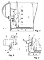
- a kettle serving as a device for heating liquids 1 comprises a liquid container 2 with one in the figures Immersion heater, not shown, which is connected in a control unit, also not shown.
- the immersion heater passes through a side wall 3 of the liquid container 2 in an opening 4.
- the control unit is arranged on the outside of the liquid holder of the liquid container 2.
- This includes one Switching arrangement for switching the heating device on and off as well an automatic switch-off for switching off the heating device when boiling or lack of fluid.
- the switching arrangement further includes a Control element 5, which is pivotally mounted; the swivel axis is in Figure 1 marked with the reference numeral 6. This is the control element 5 corresponding to the direction of the arrow shown in FIG. 1 pivotable.
- FIG. 1 shows the liquid container 2 of the kettle 1 placed to a base station 9.
- the base station 9 is connected to a voltage source connected. The necessary are to simplify the presentation electrical connector parts, one of which is the liquid container 2 and another is assigned to the base station 9, not shown. In the arrangement shown in Figure 1, these are two Plug-in parts placed in engagement with each other, so that the heating device can be powered.
- Figure 1 shows the control element 5 and thus the switch arrangement in its ON position. For manual Switching off the heating device is the control element 5 down to to move the lower end of the liquid container 2, thereby this exercises the above-mentioned pivoting movement.
- the control element 5 is in the ON position shown in Figure 1 by a Locked and held under a spring tension, so that Switching off the switch arrangement, the control element 5 only via the detent must be led away. The further switch-off movement is spring-assisted and therefore automatic.
- the actuator 7 engages behind with its hook element 9 Undercut of the base station 9, in the illustrated embodiment is integrated in the roof of the power supply unit.
- the control element 5 with the switching hook 7 formed therein and the Hook element 8 is shown again in FIG. 2.
- the switch arrangement should be switched on.
- the hook element 8 of the shift hook 7 is on the underside equipped with a ramp surface 10, so that even when the Liquid container 2 through the hook element 7 on the control element 5 a torque is applied to turn it off.
- FIG 4 shows a further kettle 11, which is constructed in principle like the kettle 1 of Figures 1 to 3, but different from this by the provided actuator 12 for switching off the heating device of the liquid container 13 when lifting the same from the base station 14 differs.
- the actuator 12 is according to Art a switching spring designed a frame-shaped adjusting section 15th and a lower support portion 16.
- the control section 15 surrounds
- the control element 17 of the liquid container 13 is formed on the upper side on the actuating section 15 are two spring sections 18, 18 '. This are with their free ends on the liquid container 13 of the kettle 11 determined how this is shown schematically in Figure 4 is.
- the support section 16 is supported when it is placed on the base station 14 Liquid container 13 - as shown in Figure 4 - on the top a cover of the power supply unit of the base station 14 from.
- the support section is underside with a Support foot 19 equipped.
- the spring sections 18, 18 ' are as tension springs trained and are in the position shown in Figure 4 under spring preload and are therefore stretched.
- the extension of the spring sections 18, 18 ' takes place by placing the liquid container 13 on the Base station 14, the adjusting section 15 and the supporting section 16 relative to the fixing of the spring sections 18, 18 'on the liquid container 13 can be moved upwards.
- the switching spring 12 is shown again with its individual elements in Figure 5.
- FIG 7 shows another kettle 20, the liquid container 21 is placed on a base station 22.
- Switching ribs 23, 23 ' which work accordingly in terms of their function as the actuator 12 of Figures 4 to 6.
- the switching ribs 23, 23 ' are part of the liquid container 21 and have two on the top switching webs 25, 25 'extending over the operating element 24.
- Of the switching ribs 23, 23 'pointing inwards towards one another are also - As can be seen in Figure 8 - two adjusting ribs 26, 26 'formed, which at on the base station 22 attached liquid container 21 on the housing support the power supply unit E and for this reason be pushed outwards.
- Figure 9 shows the switching ribs 23, 23 'of the embodiment of the figures 7 and 8 with its individual parts.
- a recess 28 is provided, in which the Housing of the power supply unit E when putting on the liquid container 21 is inserted onto the base station 22.
Landscapes
- Engineering & Computer Science (AREA)
- Food Science & Technology (AREA)
- Cookers (AREA)
- Details Of Rigid Or Semi-Rigid Containers (AREA)
- Control Of Resistance Heating (AREA)
- Apparatus For Making Beverages (AREA)
- Coating Apparatus (AREA)
- Food Preservation Except Freezing, Refrigeration, And Drying (AREA)
Abstract
Description
- Fig.1:
- Einen schematisierten Längsschnitt durch einen schnurlosen Wasserkocher mit einem Betätigungsglied zum zwangsweisen Ausschalten der Heizeinrichtung des Wasserkochers beim Abnehmen desselben von einer Basisstation,
- Fig.2:
- eine dreidimensionale Darstellung des Betätigungsgliedes des Wasserkochers der Figur 1,
- Fig. 3:
- einen Ausschnitt aus der Darstellung des Wasserkochers der Figur 1, darstellend eine Situation beim Abheben des Flüssigkeitsbehälters,
- Fig. 4:
- einen schematisierten Längsschnitt durch einen weiteren schnurlosen Wasserkocher mit einem Betätigungsglied zum zwangsweisen Ausschalten der Heizeinrichtung des Wasserkochers beim Abnehmen desselben von einer Basisstation,
- Fig. 5:
- eine dreidimensionale Darstellung des Betätigungsgliedes des Wasserkochers der Figur 4,
- Fig. 6:
- einen Ausschnitt aus der Darstellung des Wasserkochers der Figur 4, darstellend eine Situation beim Abheben des Flüssigkeitsbehälters,
- Fig. 7:
- einen schematisierten Längsschnitt durch noch einen weiteren schnurlosen Wasserkocher mit einem Betätigungsglied zum zwangsweisen Ausschalten der Heizeinrichtung des Wasserkochers beim Abnehmen desselben von einer Basisstation,
- Fig. 8:
- einen Schnitt entlang der Linie A-A durch den Wasserkocher der Figur 7 und
- Fig. 9:
- eine dreidimensionale Darstellung des Betätigungsgliedes des Wasserkochers der Figuren 7 und 8.
- 1
- Wasserkocher
- 2
- Flüssigkeitsbehälter
- 3
- Seitenwand
- 4
- Durchbrechung
- 5
- Bedienelement
- 6
- Schwenkachse
- 7
- Betätigungsglied
- 8
- Hakenelement
- 9
- Basisstation
- 10
- Auflauffläche
- 11
- Wasserkocher
- 12
- Betätigungsglied, Schaltfeder
- 13
- Flüssigkeitsbehälter
- 14
- Basisstation
- 15
- Stellabschnitt
- 16
- Abstützabschnitt
- 17
- Bedienelement
- 18, 18'
- Federabschnitt
- 19
- Stützfuß
- 20
- Wasserkocher
- 21
- Flüssigkeitsbehälter
- 22
- Basisstation
- 23, 23'
- Schaltrippe
- 24
- Bedienelement
- 25, 25'
- Schalsteg
- 26, 26'
- Stellrippe
- 27
- Fuß
- 28
- Durchbrechung
- E
- Energieversorgungseinheit
Claims (10)
- Vorrichtung zum Erwärmen von Flüssigkeiten, umfassend einen Flüssigkeitsbehälter (2, 13, 21) mit einer dem Behälter (2, 13, 21) zugeordneten elektrischen Heizeinrichtung zum Erwärmen von in dem Behälter befindlicher Flüssigkeit, mit einer eine Schalteranordnung zum Ein- und Ausschalten der Heizeinrichtung aufweisenden Steuereinheit und mit einem elektrischen Steckverbindungsteil zum lösbaren Kontaktieren eines Gegensteckverbindungsteil sowie umfassend eine das Gegensteckverbindungsteil tragende Basisstation (9, 14, 22), dadurch gekennzeichnet, dass die Schalteranordnung ein durch eine parallel zur Längsachse des Behälters verlaufende Schaltbewegung manuell betätigbares und in Richtung zum unteren Abschluß des Behälters (2, 13, 21) in seine AUS-Stellung schaltbares Bedienelement (5, 17, 24) umfasst und mit einem auf das Bedienelement (5, 17, 24) mechanisch einwirkenden Betätigungsglied (7, 12, 23, 23') dergestalt ausgestattet ist, dass bei einem Abheben des Behälters (2, 13, 21) von der Basisstation (5, 17, 24) der Schalteranordnung durch eine an die Abhebebewegung des Behälters (2, 13, 21) zwangsgekoppelte Bewegung des Betätigungsgliedes (7, 12, 23, 23') das Bedienelement (5, 17, 24) in seine AUS-Stellung bewegt und demzufolge die Schalteranordnung in ihre AUS-Stellung geschaltet wird.
- Vorrichtung nach Anspruch 1, dadurch gekennzeichnet, dass an dem Bedienelement (5) der Schalteranordnung als Betätigungsglied ein Schalthaken (7) angeformt ist, der bei auf der Basisstation (9) aufgesetztem Behälter (2) einen der Basisstation (9) zugeordneten Hinterschnitt hintergreifend gehalten ist und durch den bei einer Bewegung zum Herausführen desselben aus dem Hinterschnitt der Basisstation (9) das Bedienelement (5) in seine AUS-Stellung geschaltet wird.
- Vorrichtung nach Anspruch 2, dadurch gekennzeichnet, dass der Schalthaken (7) aus dem Hinterschnitt ausschwenkbar ist.
- Vorrichtung nach Anspruch 2, dadurch gekennzeichnet, dass das Bedienelement (5) der Schalteranordnung nach Art einer Wippe gelagert ist und die Schwenkbewegung des Schalthakens (7) in der schwenkbaren Lagerung des Bedienelementes (5) begründet ist.
- Vorrichtung nach Anspruch 1, dadurch gekennzeichnet, dass als Betätigungsglied eine Schaltfeder (12) vorgesehen ist, die sich bei auf der Basisstation (14) aufgesetztem Behälter (13) an der Basisstation (14) abstützt und durch diese Abstützung in ihrer gespannten Stellung gehalten ist, wobei durch deren gespeicherte Energie bei einem Abheben des Behälters (13) von der Basisstation (14) das Bedienelement (17) in seine AUS-Stellung geschaltet wird.
- Vorrichtung nach Anspruch 5, dadurch gekennzeichnet, dass die Schaltfeder (12) einen das Bedienelement (17) oberseitig umgreifenden und unterseitig einen Abstützabschnitt (16) aufweisenden Stellabschnitt (15) umfaßt, an dem zumindest ein mit seinem freien Ende am Behälter (13) festgelegter Federabschnitt (18) mit in Richtung der Längserstreckung des Stellabschnittes (15) wirkenden Federeigenschaften angeformt ist.
- Vorrichtung nach Anspruch 6, dadurch gekennzeichnet, dass zwei Federabschnitte (18, 18') vorgesehen sind.
- Vorrichtung nach Anspruch Anspruch 1, dadurch gekennzeichnet, dass als Betätigungsglied zumindest eine der Basisstation zugeordnete und in Querreichtung zur Abhebebewegung des Behälters (21) von der Basisstation (22) federelastische Schaltrippe (23) vorgesehen ist, die bei auf der Basisstation (22) aufgesetztem Behälter (21) das Bedienelement (24) oberseitig zumindest teilweise übergreift, wobei die durch die Schaltrippe (23) bereitgestellten, auf das Bedienelement (24) bei einer Abhebebewegung des Behälters (21) von der Basisstation (22) einwirkenden Kräfte größer sind als die zum Bewegen und Belassen des Bedienelementes (24) in seiner EIN-Stellung benötigten.
- Vorrichtung nach Anspruch 8, dadurch gekennzeichnet, dass zwei Schaltrippen (23, 23') vorgesehen sind.
- Vorrichtung nach Anspruch 8 oder 9, dadurch gekennzeichnet, dass die Schaltrippe (23, 23') ein Kunststoffteil ist.
Applications Claiming Priority (2)
| Application Number | Priority Date | Filing Date | Title |
|---|---|---|---|
| DE20211099U DE20211099U1 (de) | 2002-07-23 | 2002-07-23 | Vorrichtung zum Erwärmen von Flüssigkeiten |
| DE20211099U | 2002-07-23 |
Publications (2)
| Publication Number | Publication Date |
|---|---|
| EP1385184A1 true EP1385184A1 (de) | 2004-01-28 |
| EP1385184B1 EP1385184B1 (de) | 2006-10-25 |
Family
ID=7973283
Family Applications (1)
| Application Number | Title | Priority Date | Filing Date |
|---|---|---|---|
| EP03015235A Expired - Lifetime EP1385184B1 (de) | 2002-07-23 | 2003-07-05 | Vorrichtung zum Erwärmen von Flüssigkeiten |
Country Status (7)
| Country | Link |
|---|---|
| EP (1) | EP1385184B1 (de) |
| CN (1) | CN2708799Y (de) |
| AT (1) | ATE343845T1 (de) |
| AU (1) | AU2003208138B2 (de) |
| DE (2) | DE20211099U1 (de) |
| ES (1) | ES2274145T3 (de) |
| HK (1) | HK1055057A2 (de) |
Cited By (2)
| Publication number | Priority date | Publication date | Assignee | Title |
|---|---|---|---|---|
| JP2010082381A (ja) * | 2008-10-02 | 2010-04-15 | Zojirushi Corp | 手注ぎ式機器 |
| EP2543286A1 (de) * | 2011-07-04 | 2013-01-09 | Chuandong Magnetic Electronic Co., Ltd. | Neue magnetoempfindliche Temperatursteuerungsvorrichtung für elektrischen Heizbehälter |
Families Citing this family (2)
| Publication number | Priority date | Publication date | Assignee | Title |
|---|---|---|---|---|
| CN102610439B (zh) * | 2011-12-16 | 2015-02-25 | 佛山市川东磁电股份有限公司 | 一种电热容器磁敏温控装置 |
| GB201818785D0 (en) | 2018-11-19 | 2019-01-02 | Collinson Marc Gibson | A liquif hrsting device for induction hobs |
Citations (5)
| Publication number | Priority date | Publication date | Assignee | Title |
|---|---|---|---|---|
| EP0303886A2 (de) * | 1987-08-15 | 1989-02-22 | Stephan Vandaele | Elektrische Haushaltgeräte-anordnung |
| GB2303977A (en) * | 1996-10-29 | 1997-03-05 | Dualit Ltd | Cordless electric kettle |
| EP0719464B1 (de) | 1993-09-16 | 1999-02-17 | Strix Limited | Schnurloses haushaltsgerät und elektrischer steckverbinder dafür |
| WO2001056437A2 (en) | 2000-01-31 | 2001-08-09 | Strix Limited | Controls for electric liquid heating vessels |
| GB2361815A (en) * | 2000-04-26 | 2001-10-31 | Otter Controls Ltd | Cordless electrical appliance having connector with retractable pins |
-
2002
- 2002-07-23 DE DE20211099U patent/DE20211099U1/de not_active Expired - Lifetime
-
2003
- 2003-07-05 AT AT03015235T patent/ATE343845T1/de not_active IP Right Cessation
- 2003-07-05 DE DE50305467T patent/DE50305467D1/de not_active Expired - Lifetime
- 2003-07-05 EP EP03015235A patent/EP1385184B1/de not_active Expired - Lifetime
- 2003-07-05 ES ES03015235T patent/ES2274145T3/es not_active Expired - Lifetime
- 2003-07-07 AU AU2003208138A patent/AU2003208138B2/en not_active Ceased
- 2003-07-23 HK HK03105324A patent/HK1055057A2/xx not_active IP Right Cessation
- 2003-07-23 CN CNU032050909U patent/CN2708799Y/zh not_active Expired - Lifetime
Patent Citations (5)
| Publication number | Priority date | Publication date | Assignee | Title |
|---|---|---|---|---|
| EP0303886A2 (de) * | 1987-08-15 | 1989-02-22 | Stephan Vandaele | Elektrische Haushaltgeräte-anordnung |
| EP0719464B1 (de) | 1993-09-16 | 1999-02-17 | Strix Limited | Schnurloses haushaltsgerät und elektrischer steckverbinder dafür |
| GB2303977A (en) * | 1996-10-29 | 1997-03-05 | Dualit Ltd | Cordless electric kettle |
| WO2001056437A2 (en) | 2000-01-31 | 2001-08-09 | Strix Limited | Controls for electric liquid heating vessels |
| GB2361815A (en) * | 2000-04-26 | 2001-10-31 | Otter Controls Ltd | Cordless electrical appliance having connector with retractable pins |
Cited By (2)
| Publication number | Priority date | Publication date | Assignee | Title |
|---|---|---|---|---|
| JP2010082381A (ja) * | 2008-10-02 | 2010-04-15 | Zojirushi Corp | 手注ぎ式機器 |
| EP2543286A1 (de) * | 2011-07-04 | 2013-01-09 | Chuandong Magnetic Electronic Co., Ltd. | Neue magnetoempfindliche Temperatursteuerungsvorrichtung für elektrischen Heizbehälter |
Also Published As
| Publication number | Publication date |
|---|---|
| DE50305467D1 (de) | 2006-12-07 |
| DE20211099U1 (de) | 2002-10-10 |
| CN2708799Y (zh) | 2005-07-13 |
| ATE343845T1 (de) | 2006-11-15 |
| HK1055057A2 (en) | 2003-12-05 |
| AU2003208138A1 (en) | 2004-02-12 |
| AU2003208138B2 (en) | 2008-05-29 |
| EP1385184B1 (de) | 2006-10-25 |
| ES2274145T3 (es) | 2007-05-16 |
Similar Documents
| Publication | Publication Date | Title |
|---|---|---|
| DE60011796T2 (de) | Automatische sicherheits-und blockierschaltvorrichtung für den schlitten eines toasters | |
| EP1051096A1 (de) | Vorrichtung zum anziehen von strumpfwaren und antriebseinheit hierfür | |
| DE19943775C2 (de) | Automatisch sich öffnender und schließender, mehrfach faltbarer Schirm | |
| DE102017117509A1 (de) | Elektrisches Gerät | |
| DE102011107319B4 (de) | Flachwischer und Trägerplatte dafür | |
| DE2433156B2 (de) | Tastschalter | |
| DE2608500A1 (de) | Buegeleisen | |
| EP1385184B1 (de) | Vorrichtung zum Erwärmen von Flüssigkeiten | |
| EP1432075B1 (de) | Klemme für den Anschluss eines elektrischen Leiters | |
| DE102020129630B4 (de) | Eine auslöserschalterbaugruppe mit einem verriegelungsmechanismus | |
| DE10131636A1 (de) | Türverriegelungsvorrichtung, insbesondere für ein elektrisches Haushaltsgerät | |
| DE10322654B4 (de) | Schaltgerät | |
| DE19736821C2 (de) | Gerät zum Erhitzen einer Flüssigkeit | |
| DE10234316B4 (de) | Mischgerät mit einem elektrischen Antriebsmotor und Sicherheitseinrichtung | |
| DE102019133319A1 (de) | Unterflurinstallationsbauteil | |
| DE7635497U1 (de) | Heckenschere mit elektromotorischem Antrieb | |
| DE2754195A1 (de) | Gruppenschalter | |
| DE102013114918A1 (de) | Medizintechnische Fußsteuerung | |
| AT505602A1 (de) | Schaltgerät | |
| DE102007055607B4 (de) | Schalter und seine Verwendung zum Betätigen eines Hub-Schiebedachs in einem Fahrzeug | |
| EP1661496B1 (de) | Transportbügel | |
| DE60027090T2 (de) | Elektromagnetischer Schaltmechanismus mit manuell betätigter Rückstellvorrichtung | |
| EP2273205B1 (de) | Befestigungssystem für Rohrhalter für Installationsrohre, insbesondere Fußbodenheizungsrohre | |
| DE60026085T2 (de) | Automatische Sicherheits- und Blockierschaltvorrichtung für den Schlitten eines Toasters | |
| EP2064722B1 (de) | Sicherungs-lasttrennschalter mit einstellbarer hilfsschalterbetätigung |
Legal Events
| Date | Code | Title | Description |
|---|---|---|---|
| PUAI | Public reference made under article 153(3) epc to a published international application that has entered the european phase |
Free format text: ORIGINAL CODE: 0009012 |
|
| AK | Designated contracting states |
Kind code of ref document: A1 Designated state(s): AT BE BG CH CY CZ DE DK EE ES FI FR GB GR HU IE IT LI LU MC NL PT RO SE SI SK TR |
|
| AX | Request for extension of the european patent |
Extension state: AL LT LV MK |
|
| 17P | Request for examination filed |
Effective date: 20040714 |
|
| AKX | Designation fees paid |
Designated state(s): AT BE BG CH CY CZ DE DK EE ES FI FR GB GR HU IE IT LI LU MC NL PT RO SE SI SK TR |
|
| GRAP | Despatch of communication of intention to grant a patent |
Free format text: ORIGINAL CODE: EPIDOSNIGR1 |
|
| GRAS | Grant fee paid |
Free format text: ORIGINAL CODE: EPIDOSNIGR3 |
|
| GRAA | (expected) grant |
Free format text: ORIGINAL CODE: 0009210 |
|
| AK | Designated contracting states |
Kind code of ref document: B1 Designated state(s): AT BE BG CH CY CZ DE DK EE ES FI FR GB GR HU IE IT LI LU MC NL PT RO SE SI SK TR |
|
| PG25 | Lapsed in a contracting state [announced via postgrant information from national office to epo] |
Ref country code: IT Free format text: LAPSE BECAUSE OF FAILURE TO SUBMIT A TRANSLATION OF THE DESCRIPTION OR TO PAY THE FEE WITHIN THE PRESCRIBED TIME-LIMIT;WARNING: LAPSES OF ITALIAN PATENTS WITH EFFECTIVE DATE BEFORE 2007 MAY HAVE OCCURRED AT ANY TIME BEFORE 2007. THE CORRECT EFFECTIVE DATE MAY BE DIFFERENT FROM THE ONE RECORDED. Effective date: 20061025 Ref country code: SK Free format text: LAPSE BECAUSE OF FAILURE TO SUBMIT A TRANSLATION OF THE DESCRIPTION OR TO PAY THE FEE WITHIN THE PRESCRIBED TIME-LIMIT Effective date: 20061025 Ref country code: FI Free format text: LAPSE BECAUSE OF FAILURE TO SUBMIT A TRANSLATION OF THE DESCRIPTION OR TO PAY THE FEE WITHIN THE PRESCRIBED TIME-LIMIT Effective date: 20061025 Ref country code: IE Free format text: LAPSE BECAUSE OF FAILURE TO SUBMIT A TRANSLATION OF THE DESCRIPTION OR TO PAY THE FEE WITHIN THE PRESCRIBED TIME-LIMIT Effective date: 20061025 Ref country code: SI Free format text: LAPSE BECAUSE OF FAILURE TO SUBMIT A TRANSLATION OF THE DESCRIPTION OR TO PAY THE FEE WITHIN THE PRESCRIBED TIME-LIMIT Effective date: 20061025 Ref country code: CZ Free format text: LAPSE BECAUSE OF FAILURE TO SUBMIT A TRANSLATION OF THE DESCRIPTION OR TO PAY THE FEE WITHIN THE PRESCRIBED TIME-LIMIT Effective date: 20061025 Ref country code: RO Free format text: LAPSE BECAUSE OF FAILURE TO SUBMIT A TRANSLATION OF THE DESCRIPTION OR TO PAY THE FEE WITHIN THE PRESCRIBED TIME-LIMIT Effective date: 20061025 |
|
| REG | Reference to a national code |
Ref country code: GB Ref legal event code: FG4D Free format text: NOT ENGLISH |
|
| REG | Reference to a national code |
Ref country code: CH Ref legal event code: EP |
|
| REG | Reference to a national code |
Ref country code: IE Ref legal event code: FG4D Free format text: LANGUAGE OF EP DOCUMENT: GERMAN |
|
| REF | Corresponds to: |
Ref document number: 50305467 Country of ref document: DE Date of ref document: 20061207 Kind code of ref document: P |
|
| REG | Reference to a national code |
Ref country code: CH Ref legal event code: NV Representative=s name: PA ALDO ROEMPLER |
|
| PG25 | Lapsed in a contracting state [announced via postgrant information from national office to epo] |
Ref country code: SE Free format text: LAPSE BECAUSE OF FAILURE TO SUBMIT A TRANSLATION OF THE DESCRIPTION OR TO PAY THE FEE WITHIN THE PRESCRIBED TIME-LIMIT Effective date: 20070125 Ref country code: DK Free format text: LAPSE BECAUSE OF FAILURE TO SUBMIT A TRANSLATION OF THE DESCRIPTION OR TO PAY THE FEE WITHIN THE PRESCRIBED TIME-LIMIT Effective date: 20070125 Ref country code: BG Free format text: LAPSE BECAUSE OF FAILURE TO SUBMIT A TRANSLATION OF THE DESCRIPTION OR TO PAY THE FEE WITHIN THE PRESCRIBED TIME-LIMIT Effective date: 20070125 |
|
| GBT | Gb: translation of ep patent filed (gb section 77(6)(a)/1977) |
Effective date: 20070131 |
|
| ET | Fr: translation filed | ||
| PG25 | Lapsed in a contracting state [announced via postgrant information from national office to epo] |
Ref country code: PT Free format text: LAPSE BECAUSE OF FAILURE TO SUBMIT A TRANSLATION OF THE DESCRIPTION OR TO PAY THE FEE WITHIN THE PRESCRIBED TIME-LIMIT Effective date: 20070326 |
|
| REG | Reference to a national code |
Ref country code: ES Ref legal event code: FG2A Ref document number: 2274145 Country of ref document: ES Kind code of ref document: T3 |
|
| REG | Reference to a national code |
Ref country code: IE Ref legal event code: FD4D |
|
| PLBE | No opposition filed within time limit |
Free format text: ORIGINAL CODE: 0009261 |
|
| STAA | Information on the status of an ep patent application or granted ep patent |
Free format text: STATUS: NO OPPOSITION FILED WITHIN TIME LIMIT |
|
| 26N | No opposition filed |
Effective date: 20070726 |
|
| BERE | Be: lapsed |
Owner name: WIK FAR EAST LTD. Effective date: 20070731 |
|
| PG25 | Lapsed in a contracting state [announced via postgrant information from national office to epo] |
Ref country code: MC Free format text: LAPSE BECAUSE OF NON-PAYMENT OF DUE FEES Effective date: 20070731 Ref country code: GR Free format text: LAPSE BECAUSE OF FAILURE TO SUBMIT A TRANSLATION OF THE DESCRIPTION OR TO PAY THE FEE WITHIN THE PRESCRIBED TIME-LIMIT Effective date: 20070126 |
|
| PG25 | Lapsed in a contracting state [announced via postgrant information from national office to epo] |
Ref country code: BE Free format text: LAPSE BECAUSE OF NON-PAYMENT OF DUE FEES Effective date: 20070731 |
|
| REG | Reference to a national code |
Ref country code: CH Ref legal event code: PCAR Free format text: ALDO ROEMPLER PATENTANWALT;BRENDENWEG 11 POSTFACH 154;9424 RHEINECK (CH) |
|
| PG25 | Lapsed in a contracting state [announced via postgrant information from national office to epo] |
Ref country code: AT Free format text: LAPSE BECAUSE OF NON-PAYMENT OF DUE FEES Effective date: 20070705 |
|
| PG25 | Lapsed in a contracting state [announced via postgrant information from national office to epo] |
Ref country code: EE Free format text: LAPSE BECAUSE OF FAILURE TO SUBMIT A TRANSLATION OF THE DESCRIPTION OR TO PAY THE FEE WITHIN THE PRESCRIBED TIME-LIMIT Effective date: 20061025 |
|
| PG25 | Lapsed in a contracting state [announced via postgrant information from national office to epo] |
Ref country code: LU Free format text: LAPSE BECAUSE OF NON-PAYMENT OF DUE FEES Effective date: 20070705 Ref country code: CY Free format text: LAPSE BECAUSE OF FAILURE TO SUBMIT A TRANSLATION OF THE DESCRIPTION OR TO PAY THE FEE WITHIN THE PRESCRIBED TIME-LIMIT Effective date: 20061025 |
|
| PG25 | Lapsed in a contracting state [announced via postgrant information from national office to epo] |
Ref country code: TR Free format text: LAPSE BECAUSE OF FAILURE TO SUBMIT A TRANSLATION OF THE DESCRIPTION OR TO PAY THE FEE WITHIN THE PRESCRIBED TIME-LIMIT Effective date: 20061025 Ref country code: HU Free format text: LAPSE BECAUSE OF FAILURE TO SUBMIT A TRANSLATION OF THE DESCRIPTION OR TO PAY THE FEE WITHIN THE PRESCRIBED TIME-LIMIT Effective date: 20070426 |
|
| PGFP | Annual fee paid to national office [announced via postgrant information from national office to epo] |
Ref country code: CH Payment date: 20110725 Year of fee payment: 9 |
|
| PGFP | Annual fee paid to national office [announced via postgrant information from national office to epo] |
Ref country code: NL Payment date: 20110725 Year of fee payment: 9 |
|
| PGFP | Annual fee paid to national office [announced via postgrant information from national office to epo] |
Ref country code: GB Payment date: 20120723 Year of fee payment: 10 |
|
| PGFP | Annual fee paid to national office [announced via postgrant information from national office to epo] |
Ref country code: FR Payment date: 20120803 Year of fee payment: 10 Ref country code: ES Payment date: 20120723 Year of fee payment: 10 Ref country code: DE Payment date: 20120627 Year of fee payment: 10 |
|
| REG | Reference to a national code |
Ref country code: NL Ref legal event code: V1 Effective date: 20130201 |
|
| PG25 | Lapsed in a contracting state [announced via postgrant information from national office to epo] |
Ref country code: NL Free format text: LAPSE BECAUSE OF NON-PAYMENT OF DUE FEES Effective date: 20130201 |
|
| REG | Reference to a national code |
Ref country code: CH Ref legal event code: PL |
|
| GBPC | Gb: european patent ceased through non-payment of renewal fee |
Effective date: 20130705 |
|
| REG | Reference to a national code |
Ref country code: DE Ref legal event code: R119 Ref document number: 50305467 Country of ref document: DE Effective date: 20140201 |
|
| REG | Reference to a national code |
Ref country code: FR Ref legal event code: ST Effective date: 20140331 |
|
| PG25 | Lapsed in a contracting state [announced via postgrant information from national office to epo] |
Ref country code: GB Free format text: LAPSE BECAUSE OF NON-PAYMENT OF DUE FEES Effective date: 20130705 Ref country code: CH Free format text: LAPSE BECAUSE OF NON-PAYMENT OF DUE FEES Effective date: 20130731 Ref country code: DE Free format text: LAPSE BECAUSE OF NON-PAYMENT OF DUE FEES Effective date: 20140201 Ref country code: LI Free format text: LAPSE BECAUSE OF NON-PAYMENT OF DUE FEES Effective date: 20130731 |
|
| PG25 | Lapsed in a contracting state [announced via postgrant information from national office to epo] |
Ref country code: FR Free format text: LAPSE BECAUSE OF NON-PAYMENT OF DUE FEES Effective date: 20130731 |
|
| REG | Reference to a national code |
Ref country code: ES Ref legal event code: FD2A Effective date: 20150709 |
|
| PG25 | Lapsed in a contracting state [announced via postgrant information from national office to epo] |
Ref country code: ES Free format text: LAPSE BECAUSE OF NON-PAYMENT OF DUE FEES Effective date: 20130706 |