EP1382787B1 - Mitnehmer für ein Kraftfahrzeugfenster - Google Patents
Mitnehmer für ein Kraftfahrzeugfenster Download PDFInfo
- Publication number
- EP1382787B1 EP1382787B1 EP03015004A EP03015004A EP1382787B1 EP 1382787 B1 EP1382787 B1 EP 1382787B1 EP 03015004 A EP03015004 A EP 03015004A EP 03015004 A EP03015004 A EP 03015004A EP 1382787 B1 EP1382787 B1 EP 1382787B1
- Authority
- EP
- European Patent Office
- Prior art keywords
- plate portion
- movable jaw
- screw
- support slide
- hole
- Prior art date
- Legal status (The legal status is an assumption and is not a legal conclusion. Google has not performed a legal analysis and makes no representation as to the accuracy of the status listed.)
- Expired - Lifetime
Links
Images

Classifications
-
- E—FIXED CONSTRUCTIONS
- E05—LOCKS; KEYS; WINDOW OR DOOR FITTINGS; SAFES
- E05F—DEVICES FOR MOVING WINGS INTO OPEN OR CLOSED POSITION; CHECKS FOR WINGS; WING FITTINGS NOT OTHERWISE PROVIDED FOR, CONCERNED WITH THE FUNCTIONING OF THE WING
- E05F11/00—Man-operated mechanisms for operating wings, including those which also operate the fastening
- E05F11/38—Man-operated mechanisms for operating wings, including those which also operate the fastening for sliding windows, e.g. vehicle windows, to be opened or closed by vertical movement
- E05F11/382—Man-operated mechanisms for operating wings, including those which also operate the fastening for sliding windows, e.g. vehicle windows, to be opened or closed by vertical movement for vehicle windows
-
- B—PERFORMING OPERATIONS; TRANSPORTING
- B60—VEHICLES IN GENERAL
- B60J—WINDOWS, WINDSCREENS, NON-FIXED ROOFS, DOORS, OR SIMILAR DEVICES FOR VEHICLES; REMOVABLE EXTERNAL PROTECTIVE COVERINGS SPECIALLY ADAPTED FOR VEHICLES
- B60J1/00—Windows; Windscreens; Accessories therefor
- B60J1/08—Windows; Windscreens; Accessories therefor arranged at vehicle sides
- B60J1/12—Windows; Windscreens; Accessories therefor arranged at vehicle sides adjustable
- B60J1/16—Windows; Windscreens; Accessories therefor arranged at vehicle sides adjustable slidable
- B60J1/17—Windows; Windscreens; Accessories therefor arranged at vehicle sides adjustable slidable vertically
-
- E—FIXED CONSTRUCTIONS
- E05—LOCKS; KEYS; WINDOW OR DOOR FITTINGS; SAFES
- E05F—DEVICES FOR MOVING WINGS INTO OPEN OR CLOSED POSITION; CHECKS FOR WINGS; WING FITTINGS NOT OTHERWISE PROVIDED FOR, CONCERNED WITH THE FUNCTIONING OF THE WING
- E05F11/00—Man-operated mechanisms for operating wings, including those which also operate the fastening
- E05F11/38—Man-operated mechanisms for operating wings, including those which also operate the fastening for sliding windows, e.g. vehicle windows, to be opened or closed by vertical movement
- E05F11/382—Man-operated mechanisms for operating wings, including those which also operate the fastening for sliding windows, e.g. vehicle windows, to be opened or closed by vertical movement for vehicle windows
- E05F11/385—Fixing of window glass to the carrier of the operating mechanism
-
- E—FIXED CONSTRUCTIONS
- E05—LOCKS; KEYS; WINDOW OR DOOR FITTINGS; SAFES
- E05Y—INDEXING SCHEME ASSOCIATED WITH SUBCLASSES E05D AND E05F, RELATING TO CONSTRUCTION ELEMENTS, ELECTRIC CONTROL, POWER SUPPLY, POWER SIGNAL OR TRANSMISSION, USER INTERFACES, MOUNTING OR COUPLING, DETAILS, ACCESSORIES, AUXILIARY OPERATIONS NOT OTHERWISE PROVIDED FOR, APPLICATION THEREOF
- E05Y2201/00—Constructional elements; Accessories therefor
- E05Y2201/60—Suspension or transmission members; Accessories therefor
- E05Y2201/606—Accessories therefor
- E05Y2201/61—Cooperation between suspension or transmission members
- E05Y2201/612—Cooperation between suspension or transmission members between carriers and rails
-
- E—FIXED CONSTRUCTIONS
- E05—LOCKS; KEYS; WINDOW OR DOOR FITTINGS; SAFES
- E05Y—INDEXING SCHEME ASSOCIATED WITH SUBCLASSES E05D AND E05F, RELATING TO CONSTRUCTION ELEMENTS, ELECTRIC CONTROL, POWER SUPPLY, POWER SIGNAL OR TRANSMISSION, USER INTERFACES, MOUNTING OR COUPLING, DETAILS, ACCESSORIES, AUXILIARY OPERATIONS NOT OTHERWISE PROVIDED FOR, APPLICATION THEREOF
- E05Y2600/00—Mounting or coupling arrangements for elements provided for in this subclass
- E05Y2600/50—Mounting methods; Positioning
- E05Y2600/502—Clamping
-
- E—FIXED CONSTRUCTIONS
- E05—LOCKS; KEYS; WINDOW OR DOOR FITTINGS; SAFES
- E05Y—INDEXING SCHEME ASSOCIATED WITH SUBCLASSES E05D AND E05F, RELATING TO CONSTRUCTION ELEMENTS, ELECTRIC CONTROL, POWER SUPPLY, POWER SIGNAL OR TRANSMISSION, USER INTERFACES, MOUNTING OR COUPLING, DETAILS, ACCESSORIES, AUXILIARY OPERATIONS NOT OTHERWISE PROVIDED FOR, APPLICATION THEREOF
- E05Y2800/00—Details, accessories and auxiliary operations not otherwise provided for
- E05Y2800/34—Form stability
- E05Y2800/342—Deformable
-
- E—FIXED CONSTRUCTIONS
- E05—LOCKS; KEYS; WINDOW OR DOOR FITTINGS; SAFES
- E05Y—INDEXING SCHEME ASSOCIATED WITH SUBCLASSES E05D AND E05F, RELATING TO CONSTRUCTION ELEMENTS, ELECTRIC CONTROL, POWER SUPPLY, POWER SIGNAL OR TRANSMISSION, USER INTERFACES, MOUNTING OR COUPLING, DETAILS, ACCESSORIES, AUXILIARY OPERATIONS NOT OTHERWISE PROVIDED FOR, APPLICATION THEREOF
- E05Y2900/00—Application of doors, windows, wings or fittings thereof
- E05Y2900/50—Application of doors, windows, wings or fittings thereof for vehicles
- E05Y2900/53—Type of wing
- E05Y2900/55—Windows
Definitions
- the present invention relates to a support slide according to the preamble of claim 1.
- a support slide according to the preamble of claim 1 is known from document DE-A-199 43 717.
- a support slide according to the preamble of claim 1 is also disclosed by US-A-5 622 005, in which a window pane is supported by means of a through-hole provided in the window pane.
- the object of the invention is to economically provide a slide of this kind which is adapted to resist without slackening and damages to high clamping forces of the clamp and which can smoothly slide along the guide rails of the window regulator with minimal forces of friction.
- this object is attained by means of a slide as claimed.
- Document DE-A-199 43 717 shows and describes a slide of the type considered, the constituent material of whose body is not specified.
- the plate portion is not required to resist to any compression force due to the tightening of the clamp.
- the invention also relates to a window regulator for motor vehicles comprising a slide as claimed.
- a motor vehicle door comprises a sheet metal shell, generally indicated 10, with an upper portion having an opening which constitutes a window frame 12, and with a lower room 14.
- a window pane 16 is mounted in the shell 10 and is adapted to slide between a raised position, in which it is inserted in the frame 12, and a lowered position, in which it is at least partially lowered in the room 14.
- a drive assembly, generally indicated 18, is fixed in the room 14 to raise and lower the window pane 16.
- the drive assembly 18 comprises a pair of fixed guide rails 20 which extend parallel to each other in the direction of movement of the window pane 16.
- a respective slide 22 is adapted to travel along each rail 20 and supports the window pane 16 from a lower edge 16a of the latter.
- each rail 20 has a square Z-profile, as shown in dotted lines in figure 7.
- a control unit 24 which is also in the room 14 as well, comprises a reversible electric motor 26 and a drum (not shown) which, in a known manner, is drivingly connected to the two slides 22 by respective pairs of flexible transmission members 28, which in figure 1 are constituted by sheathed cables, but which may also consist of endless transmission cables.
- FIG 1 a window regulator of the twin-guide type has been shown by way of example, but the invention can also be applied to a window regulator with a single guide rail provided with a slide 22 such as that shown in figures 2 to 7 or in figure 8, and which will be now described.
- the slide 22 according to the invention comprises a flat body 30 which is formed, as a single piece of injection-moulded plastic material, by a
- the body 30 is preferably of a wear-resistant plastic material with a low coefficient of friction, such as for example an acetal resin or a polyamide which may contain polytetrafluoroethylene as a filler.
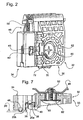
- the plate portion 32 constitutes a fixed jaw of a tightening clamp for clamping a lower edge 16a of the window pane 16, also shown in dotted lines in FIG. 6.
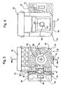
- the lateral appendage 34 has an L-section sliding channel 36 (FIGS. 2, 3, 6 and 7), which is adapted to receive a wing 20a and a web 20b of the guide rail 20, as shown in FIG. 7.
- spring members in the form of bridges 38, 40, 44 are formed in the channel 36 to take up possible plays between the rail 20 and the slide 30.
- the bridge 38 which is located in the middle region of the channel 36, has an Q configuration and its back is adapted to frontally engage the wing 20a of the rail 20, as shown in FIG. 7.
- the bridge 40 which is also located in the middle region of the channel 36, has an undulated shape and the backs of its undulations are adapted to laterally engage the edge of the wing 20a of the rail 20, still as shown in FIG. 7.
- the bridges 42 which are two in number, are located towards the opposite ends of the channel 36 and have an of the channel 36, has an undulated shape and the backs of its undulations are adapted to laterally engage the edge of the wing 20a of the rail 20, still as shown in figure 7.
- the bridges 42 which are two in number, are located towards the opposite ends of the channel 36 and have an undulated shape as well. The backs of their undulations are adapted to engage a corresponding side face of the web 20b of the rail 20, as shown in figure 7.
- the lateral appendage 34 also has, next to the sliding channel 36, inner formations 44, shown in dotted lines in figure 3, for the anchorage of the two ends of the flexible transmission members 28 of figure 1, in order to transmit the motion to the slide 22.
- a spring member having the shape of an arcuate tongue 46 (figures 2, 3 and 7), whose back is adapted to frontally engage, from the outside of the appendage 34, the other wing 20c of the rail 20, to take up the possible play between the latter and the slide 30 as well, as shown in figure 7.
- the tightening clamp for the lower edge 16a of the window pane 16 also comprises a movable jaw 48 constituted by a stamped sheet substantially flat metal piece, which cooperates with the fixed jaw constituted by the plate portion 32 in order to clamp the lower edge 16a of the window pane 16, as shown in particular in figure 6.
- a U-shaped lining 50 is interposed, in the usual way, between the two jaws 32, 40 and receives the lower edge 16a of the window pane 16.
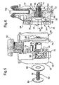
- a clamp tightening screw 52 is provided, with a threaded shank 54 which extends through a through-hole 56 (figures 5, 6 and 7) in the plate portion 32 and which engages a threaded hole 58 in the movable jaw 48, and with a head 60 which is located on a face of the plate portion 32 which is away from the face turned towards the movable jaw 48.
- a spacer in the form of a bushing 62 in the through-hole 56 of the plate portion 32 there is provided a spacer in the form of a bushing 62, a steel bushing for example, through which the shank 54 of the tightening screw 52 freely extends.
- the bushing 62 may simply be inserted with a sliding fit in the through-hole 56, may be driven in the latter with a slight force fit, or may have been incorporated in the plate portion 32 during its moulding.
- the metal bushing 62 has such a length that it projects from both the opposite sides of the plate portion 32 to constitute opposite annular end surfaces for the abutment of the head 60 of the screw 52 and of the movable jaw 48, respectively.
- the face of the plate portion 32 which corresponds to the head 60 of the screw 52, has a circular recess 64 (figures 2, 3, 6 and 7) to receive the head 60, having a bottom surface 66 (figures 6 and 7) with respect to which the corresponding ends of the bushing 62 project.
- a stress-distribution washer 68 is located in the recess 64 and is interposed between the head 60 of the screw 52 and the corresponding projecting end of the bushing 62.
- the movable jaw 48 is kept together with the fixed jaw constituted by the plate portion 32 by means of a tab 70 which has been obtained by cutting the metal sheet of the movable jaw 48 and which is inserted with play in a square loop portion 72 formed by stamping in the body 30.
- an abutment stud 74 which can be seen in figures 4, 5 and 6, is formed by moulding on the face of the plate portion 32 which is turned towards the movable jaw.
- the stud 74 acts as a rest for the lower edge 16a of the window pane 16 to make sure that this edge does not come to force on to the bottom of the U-shaped liner 50 with the risk of breaking it or, even worse, of misplacing it.
- respective arrays of strengthening ribs are advantageously moulded in the two opposite faces of the body 30.
- the spacer is constituted by a cylindrical section 62a of the shank 54a, which is contained in the hole 56 and projects from the hole 56 on the face of the plate portion 32 which is turned towards the movable jaw 48, while the head 60 of the screw 52 abuts onto the bottom wall 66 of the cylindrical recess 64 of the plate portion 32.
- the head 60a of the screw 52a has a relatively large diameter and occupies the whole space of the cylindrical recess 64 in order to distribute as much as possible the tightening force on the bottom wall 66.
- the cylindrical section 62a of the shank 54a offers a ring-like abutment surface to the movable jaw 48, which prevents it from coming into contact with the plate portion 32 and from damaging the latter when the clamp is tightened.
Landscapes
- Engineering & Computer Science (AREA)
- Mechanical Engineering (AREA)
- Window Of Vehicle (AREA)
- Power-Operated Mechanisms For Wings (AREA)
Claims (10)
- Mitnehmer für Fensterheber in Kraftfahrzeugen, umfassend:dadurch gekennzeichnet, daßeinen Körper (30), der aus einem plattenförmigen Teil (32) und einem seitlichen Ansatz (34) besteht, wobei der plattenförmige Teil eine feste Backe einer Spannzange zum Einklemmen des unteren Randes (16a) einer verschiebbaren Fensterscheibe (16) bildet, während der seitliche Ansatz einen Gleitkanal (36) für die Aufnahme einer Führungsschiene (20) aufweist,eine bewegliche Backe (48) der Spannzange, bestehend aus einem im wesentlichen flachen Formelement zum Festklemmen des unteren Randes (16a) der Fensterscheibe (16), undeine Feststellschraube (52; 52a) zum Klemmen der Spannzange, von der sich ein Gewindeschaft (54; 54a) durch eine Querbohrung (56) des plattenförmigen Teils (32) hindurch erstreckt und in eine Gewindebohrung (58) der beweglichen Backe (48) eingeschraubt ist, während ihr Kopf (60; 60a) auf einer Seite des plattenförmigen Teils liegt, die von der zur beweglichen Bache weisenden Seite abgewandt ist,wobei die bewegliche Backe (48) und die feste Backe (32) in der Weise zusammenwirken, daß sie zwischen sich die Fensterscheibe (16) einklemmenund die quer verlaufende Durchgangsbohrung (56) des plattenförmigen Teils (32) sowie die Gewindebohrung (58) der beweglichen Backe (48) unterhalb des unteren Randes (16a) der Fensterscheibe (16) angebracht sind,der Körper (30), der aus dem plattenförmigen Teil (32) und dem seitlichen Ansatz (34) besteht, als ein einstückiges Spritzgußteil aus Kunststoff hergestellt istund auf den Gewindeschaft (54; 54a) der Schraube (52; 52a) ein Abstandselement (62; 62a) aufgesetzt ist, das innerhalb der Durchgangsbohrung (56) liegt und über diese wenigstens auf der Seite des plattenförmigen Teils (32) hervorsteht, die der beweglichen Backe (48) zugewandt ist, um dadurch eine ringförmige Anlagefläche für die bewegliche Backe (48) zu bilden, wobei der Gewindeschaft in die Gewindebohrung (58) der beweglichen Backe (48) eingeschraubt ist.
- Mitnehmer nach Anspruch 1, dadurch gekennzeichnet, daß das Abstandselement aus einer metallischen Hülse (62) besteht, die in der Durchgangsbohrung (56) des plattenförmigen Teils (32) liegt und durch die sich der Gewindeschaft (54) der Feststellschraube (52) frei hindurch erstreckt, und daß die Abstandshülse (62) eine solche Länge hat, daß sie über die beiden gegenüberliegenden Seiten des plattenförmigen Teils (32) so vorsteht, daß sie gegenüberliegende, ringförmige Anlageflächen für die bewegliche Backe (48) bzw. den Kopf (60) der Schraube (52) bildet.
- Mitnehmer nach Anspruch 1, dadurch gekennzeichnet, daß das Abstandselement aus einem zylindrischen Abschnitt (62a) des Schaftes (54a) der Feststellschraube (52a) besteht, wobei dieser Abschnitt (62a) über die Bohrung auf der Seite des plattenförmigen Teils (32) vorsteht, die der beweglichen Backe (48) zugewandt ist, während der Kopf (60) der Schraube (52) an der gegenüberliegenden Seite des plattenförmigen Teils (32) anliegt.
- Mitnehmer nach einem der vorhergehenden Ansprüche, dadurch gekennzeichnet, daß der seitliche Ansatz (34) des Körpers (30) ferner derart ausgebildete Bereiche (44) hat, daß die beiden Enden eines flexiblen Übertragungsgliedes (28) verankert werden können, um die Bewegung auf den Mitnehmer (30) zu übertragen.
- Mitnehmer nach einem der vorhergehenden Ansprüche, dadurch gekennzeichnet, daß in die Seite des plattenförmigen Teils (32), auf der der Kopf (60; 60a) der Schraube (52; 52a) liegt, eine Aussparung (64) für die Aufnahme des Kopfes der Schraube eingearbeitet ist.
- Mitnehmer nach einem der Ansprüche 1, 2, 4 und 5, dadurch gekennzeichnet, daß eine Ringscheibe (68) zur Lastverteilung der Schraube (52) vorgesehen ist, die zwischen den Kopf (60) der Schraube und das entsprechende, vorstehende Ende der Hülse (62) eingesetzt ist.
- Mitnehmer nach einem der vorhergehenden Ansprüche, dadurch gekennzeichnet, daß das Kunststoffmaterial des Körpers (30) Azetalharz ist.
- Mitnehmer nach einem der Ansprüche 1 bis 6, dadurch gekennzeichnet, daß das Kunststoffmaterial des Körpers (30) Polyarmidharz ist.
- Mitnehmer nach einem der vorhergehenden Ansprüche, dadurch gekennzeichnet, daß der Körper (30) mitgeformte Federelemente (38, 40, 44, 46) zur Spielaufholung zwischen der Führungsschiene (20) des Fensterhebers und dem Körper (30) aufweist.
- Fensterheber für Kraftfahrzeuge mit einem Mitnehmer nach einem der vorhergehenden Ansprüche.
Applications Claiming Priority (2)
| Application Number | Priority Date | Filing Date | Title |
|---|---|---|---|
| ITTO20020615 | 2002-07-15 | ||
| IT2002TO000615A ITTO20020615A1 (it) | 2002-07-15 | 2002-07-15 | Pattino di sollevamento per alzacristalli di autoveicoli ed alzacristallo comprendente tale pattino |
Publications (2)
| Publication Number | Publication Date |
|---|---|
| EP1382787A1 EP1382787A1 (de) | 2004-01-21 |
| EP1382787B1 true EP1382787B1 (de) | 2005-11-23 |
Family
ID=11459496
Family Applications (1)
| Application Number | Title | Priority Date | Filing Date |
|---|---|---|---|
| EP03015004A Expired - Lifetime EP1382787B1 (de) | 2002-07-15 | 2003-07-02 | Mitnehmer für ein Kraftfahrzeugfenster |
Country Status (6)
| Country | Link |
|---|---|
| US (1) | US6854213B2 (de) |
| EP (1) | EP1382787B1 (de) |
| AT (1) | ATE310883T1 (de) |
| DE (1) | DE60302393T2 (de) |
| ES (1) | ES2253612T3 (de) |
| IT (1) | ITTO20020615A1 (de) |
Families Citing this family (39)
| Publication number | Priority date | Publication date | Assignee | Title |
|---|---|---|---|---|
| DE10345582B4 (de) * | 2003-09-29 | 2006-02-02 | Baier & Michels Gmbh & Co. Kg | Klemmelement, insbesondere für Scheiben von Kraftfahrzeugen |
| DE102004033984A1 (de) * | 2004-07-14 | 2006-02-02 | Arvinmeritor Gmbh | Klemmteil zum Halten einer Fensterscheibe bei einem Fensterheber |
| DE102005004000A1 (de) * | 2005-01-27 | 2006-08-03 | Magna Closures (Germany) Gmbh | Mitnehmer |
| DE102005020052A1 (de) * | 2005-04-29 | 2006-11-02 | Arvinmeritor Gmbh | Scheibenhalterung für einen Fensterheber |
| US7802401B2 (en) * | 2005-06-30 | 2010-09-28 | Hi-Lex Corporation | Window regulator with improved carrier |
| DE102005035197A1 (de) * | 2005-07-27 | 2007-02-01 | Arvinmeritor Gmbh | Glashaltebaugruppe für einen Fensterheber |
| US20070151159A1 (en) * | 2005-12-29 | 2007-07-05 | Hi-Lex Corporation | Universal carrier for window regulator |
| US20080306839A1 (en) * | 2006-04-28 | 2008-12-11 | Myecheck, Inc. | Method and apparatus for online check processing |
| US20080016779A1 (en) * | 2006-07-19 | 2008-01-24 | Arvinmeritor Technology, Llc | Seal and window clamp assembly |
| US7908795B2 (en) * | 2007-03-27 | 2011-03-22 | Hi-Lex Controls Inc. | Window carrier assembly for automotive window regulator |
| US8096080B2 (en) | 2007-07-04 | 2012-01-17 | Magna Closures Inc. | Adjustable window regulator lifter plate assembly for a vehicle window |
| US7721487B2 (en) * | 2007-08-10 | 2010-05-25 | Gm Global Technology Operations, Inc. | Glass attachment for movable vehicle window |
| ES2317791B1 (es) * | 2007-10-09 | 2010-01-22 | Melchor Daumal Castellon | Mejoras introducidas en la placa base o arrastrador integrante de los dispositivos elevalunas para automoviles. |
| US20090090064A1 (en) * | 2007-10-09 | 2009-04-09 | Tudora Spiridon-Sorin S | Lifter plate with energy absorption members |
| DE102008009861B4 (de) * | 2008-02-19 | 2013-10-31 | Küster Automotive Door Systems GmbH | Mitnehmer eines Seilzugfensterhebers |
| US20090223133A1 (en) * | 2008-03-07 | 2009-09-10 | Traian Miu | Self Locking Lifter Plate |
| US8453383B2 (en) * | 2008-08-20 | 2013-06-04 | Inteva Products, Llc | Adjustable glass clamp for cable drive window regulators |
| DE102009031565A1 (de) * | 2009-06-29 | 2010-12-30 | Brose Fahrzeugteile Gmbh & Co. Kommanditgesellschaft, Coburg | Mitnehmer zur Anbindung einer Fensterscheibe an einen Fensterheber eines Kraftfahrzeugs |
| KR101081177B1 (ko) | 2009-08-19 | 2011-11-07 | 기아자동차주식회사 | 도어 승강장치 |
| DE102009052569A1 (de) * | 2009-11-10 | 2011-05-12 | Arvinmeritor Gmbh | Schlitten für einen Fahrzeugfensterheber und Fahrzeugstruktur mit einem Fensterheber |
| US8381446B2 (en) * | 2011-03-29 | 2013-02-26 | Brose Fahrzeugteile Gmbh & Co. Kg, Coburg | Device for connecting a window pane to a motor vehicle window lifter |
| CN102155136A (zh) * | 2011-05-30 | 2011-08-17 | 张家港合众汽车部件有限公司 | 玻璃升降器 |
| US8739467B2 (en) | 2011-12-19 | 2014-06-03 | Chrysler Group Llc | Window regulator glass attachment guide cover |
| JP6160961B2 (ja) * | 2011-12-26 | 2017-07-12 | 株式会社ハイレックスコーポレーション | 車両用ドア構造 |
| KR101383000B1 (ko) * | 2012-09-27 | 2014-04-08 | 현대자동차주식회사 | 도어 글라스 클램프장치 |
| JP6067127B2 (ja) * | 2013-09-02 | 2017-01-25 | 本田技研工業株式会社 | 車両用ドア |
| US10273733B2 (en) * | 2017-05-15 | 2019-04-30 | Hsin Chong Machinery Works Co. Ltd. | Adjustable glass gripping device for a vehicle window regulator |
| US20190078366A1 (en) * | 2017-09-08 | 2019-03-14 | Magna Closures Inc. | Light weight two piece frameless door module with adjustment features |
| DE102018200925A1 (de) * | 2018-01-22 | 2019-07-25 | Brose Fahrzeugteile Gmbh & Co. Kommanditgesellschaft, Bamberg | Mitnehmer mit schwenkbarem Klemmteil und Montageverfahren |
| US11022165B2 (en) | 2018-04-05 | 2021-06-01 | Taylor Made Group, Llc | Spacer insert |
| DE102019131998A1 (de) * | 2018-11-29 | 2020-06-04 | Magna Closures Inc. | Verstellbare hebeplatte für rahmenlose tür |
| US11499361B2 (en) * | 2019-02-05 | 2022-11-15 | Magna Closures Inc. | Lightweight lifter plate assembly for vehicle window |
| US11577583B2 (en) * | 2019-04-26 | 2023-02-14 | Inteva Products, Llc | Pivoting cursor for frameless glass in a vehicle |
| US12030571B2 (en) * | 2019-12-10 | 2024-07-09 | Ford Global Technologies, Llc | Setting bracket for bolster adjustment |
| KR102228154B1 (ko) * | 2019-12-12 | 2021-03-16 | 대동하이렉스 주식회사 | 윈도우 레귤레이터의 클램프 볼트 이탈 방지 가이드 |
| DE102020201818A1 (de) * | 2020-02-13 | 2021-08-19 | Brose Fahrzeugteile Se & Co. Kommanditgesellschaft, Bamberg | Mitnehmer für einen Fahrzeugfensterheber |
| DE202022101779U1 (de) | 2021-04-06 | 2022-07-19 | Inteva Products, Llc | Schwenkbarer Schieber für rahmenloses Glas in einem Fahrzeug |
| DE102021209238A1 (de) * | 2021-08-23 | 2023-02-23 | Brose Fahrzeugteile Se & Co. Kommanditgesellschaft, Bamberg | Mitnehmer für einen Fahrzeugfensterheber |
| CN115071387B (zh) * | 2022-07-21 | 2024-12-03 | 福耀玻璃工业集团股份有限公司 | 托架结构、无框车门及车辆 |
Family Cites Families (20)
| Publication number | Priority date | Publication date | Assignee | Title |
|---|---|---|---|---|
| JPH0650250Y2 (ja) * | 1986-03-03 | 1994-12-21 | 株式会社ニフコ | 車輌用窓ガラスのホルダ− |
| US4848032A (en) * | 1988-12-27 | 1989-07-18 | Chrysler Motors Corporation | Arrangement for mounting automotive glass to liftplate |
| US5515651A (en) * | 1993-08-02 | 1996-05-14 | Brose Fahrzeugteile Gmbh & Co. Kg | Device for fastening a window of a motor vehicle in the guide device of a window lifter |
| US5537783A (en) * | 1993-11-09 | 1996-07-23 | Aoyama Seisakusho Co., Ltd. | Holder for a window glass of a vehicle |
| US5363595A (en) * | 1993-12-28 | 1994-11-15 | General Motors Corporation | Arrangement of a vehicle door with extendable window |
| JP3273690B2 (ja) * | 1994-03-24 | 2002-04-08 | 株式会社ニフコ | ガラスホルダー |
| DE4437532C2 (de) * | 1994-10-20 | 1996-12-12 | Brose Fahrzeugteile | Vorrichtung zum Verbinden eines Fensterhebers mit der verschiebbaren Fensterscheibe eines Kraftfahrzeugs |
| US5622005A (en) * | 1995-11-06 | 1997-04-22 | General Motors Corporation | Automotive door glass assembly |
| JPH09323542A (ja) * | 1996-06-07 | 1997-12-16 | Nifco Inc | ガラスホルダー |
| DE19653046A1 (de) * | 1996-12-19 | 1998-06-25 | Brose Fahrzeugteile | Vorrichtung zur Befestigung einer verschiebbaren Fensterscheibe eines Kraftfahrzeugs an der Führungsvorrichtung eines Fensterhebers |
| US5966872A (en) * | 1997-08-08 | 1999-10-19 | Chrysler Corporation | Vehicle door glass liftplate assembly with frangible sleeve |
| DE19742458C1 (de) * | 1997-09-26 | 1998-11-26 | Telefunken Microelectron | Kunststoffgehäuse zur Aufnahme einer elektrischen Leiterplatte |
| FR2778200B1 (fr) * | 1998-04-29 | 2000-07-21 | Meritor Light Vehicle Sys Ltd | Dispositif de support d'une vitre sur un leve-vitre de porte de vehicule |
| DE19819953A1 (de) * | 1998-05-05 | 1999-11-18 | Brose Fahrzeugteile | Einstellbarer Mitnehmer zur Anbindung einer Fensterscheibe an einen Fensterheber einer Kraftfahrzeugtür |
| FR2781006B1 (fr) * | 1998-07-08 | 2000-10-06 | Meritor Light Vehicle Sys Ltd | Dispositif de leve-vitre de porte de vehicule automobile |
| FR2812680B1 (fr) * | 2000-08-04 | 2002-11-08 | Meritor Light Vehicle Sys Ltd | Systeme de positionnement et d'assemblage d'une vitre sur un leve-vitre |
| DE10039841A1 (de) * | 2000-08-10 | 2002-02-28 | Meritor Automotive Gmbh | Vorrichtung zum Verbinden einer ein- und ausfahrbaren Kraftfahrzeug-Fensterscheibe mit einem Antriebselement |
| JP3756750B2 (ja) * | 2000-10-31 | 2006-03-15 | 株式会社大井製作所 | ウインドレギュレータのウインドパネル支持構造 |
| DE20112454U1 (de) * | 2001-07-23 | 2001-09-20 | Brose Fahrzeugteile GmbH & Co. KG, Coburg, 96450 Coburg | Mitnehmer für einen Kraftfahrzeugfensterheber |
| US6598345B1 (en) * | 2001-08-22 | 2003-07-29 | Hi-Lex Corporation | Window regulator having a cam member for lateral adjustment |
-
2002
- 2002-07-15 IT IT2002TO000615A patent/ITTO20020615A1/it unknown
-
2003
- 2003-07-02 DE DE60302393T patent/DE60302393T2/de not_active Expired - Lifetime
- 2003-07-02 AT AT03015004T patent/ATE310883T1/de not_active IP Right Cessation
- 2003-07-02 EP EP03015004A patent/EP1382787B1/de not_active Expired - Lifetime
- 2003-07-02 ES ES03015004T patent/ES2253612T3/es not_active Expired - Lifetime
- 2003-07-14 US US10/617,824 patent/US6854213B2/en not_active Expired - Fee Related
Also Published As
| Publication number | Publication date |
|---|---|
| DE60302393D1 (de) | 2005-12-29 |
| ITTO20020615A1 (it) | 2004-01-15 |
| US6854213B2 (en) | 2005-02-15 |
| ATE310883T1 (de) | 2005-12-15 |
| ES2253612T3 (es) | 2006-06-01 |
| ITTO20020615A0 (it) | 2002-07-15 |
| US20040107645A1 (en) | 2004-06-10 |
| DE60302393T2 (de) | 2006-08-10 |
| EP1382787A1 (de) | 2004-01-21 |
Similar Documents
| Publication | Publication Date | Title |
|---|---|---|
| US6854213B2 (en) | Support slide for window regulators of motor vehicles | |
| US7908795B2 (en) | Window carrier assembly for automotive window regulator | |
| US4657523A (en) | Unidirectional cable-tightening device for a motor vehicle glass raiser | |
| US5809695A (en) | Window regulator | |
| US6598345B1 (en) | Window regulator having a cam member for lateral adjustment | |
| US20020045503A1 (en) | Blade-type mechanical chain tensioner with external strengthening rib | |
| US9822568B2 (en) | Window regulator cable guide | |
| WO2010063312A1 (en) | Sunshade assembly and open roof construction provided therewith | |
| CA2576082A1 (en) | Dual-guided single rail window regulator | |
| KR102052925B1 (ko) | 차량용 컵홀더 장치의 커버 | |
| EP0629520A2 (de) | Scheibenführung für verschiebbare Fahrzeugscheiben | |
| GB2485104A (en) | Window regulator | |
| JP2011527392A (ja) | 自動車の経路制御式のウィンドウリフタ | |
| EP1994250A2 (de) | Scharniere und teile dafür | |
| KR20110106350A (ko) | 웨지 드라이브 | |
| NL1011859C2 (nl) | Open-dakconstructie voor een voertuig. | |
| US6024404A (en) | Control assembly for sunroofs for vehicles | |
| JPH01282019A (ja) | 特に、車両のスライドルーフのためのすべりシュー | |
| KR20190095387A (ko) | 견인 수단을 속박하기 위한 속박 요소 및 속박 부분을 갖는 윈도우 리프트 조립체 | |
| US10577849B2 (en) | Window regulator cable guide | |
| KR20110131118A (ko) | 비평행 유도장치가 있는 슬라이딩 윈도우 어셈블리용 슬라이딩 윈도우 유도장치 | |
| US6890025B2 (en) | Guide arrangement for a roof element on an opening vehicle roof | |
| US6802560B2 (en) | Sunroof apparatus for vehicle | |
| US5758901A (en) | Height adjusting mechanism for a safety belt device | |
| US20080153643A1 (en) | Flexible Drive Comprising at Least One Guide for Tensioning and/or Guiding a Continuous Traction Mechanism |
Legal Events
| Date | Code | Title | Description |
|---|---|---|---|
| PUAI | Public reference made under article 153(3) epc to a published international application that has entered the european phase |
Free format text: ORIGINAL CODE: 0009012 |
|
| AK | Designated contracting states |
Kind code of ref document: A1 Designated state(s): AT BE BG CH CY CZ DE DK EE ES FI FR GB GR HU IE IT LI LU MC NL PT RO SE SI SK TR |
|
| AX | Request for extension of the european patent |
Extension state: AL LT LV MK |
|
| 17P | Request for examination filed |
Effective date: 20040706 |
|
| AKX | Designation fees paid |
Designated state(s): AT BE BG CH CY CZ DE DK EE ES FI FR GB GR HU IE IT LI LU MC NL PT RO SE SI SK TR |
|
| 17Q | First examination report despatched |
Effective date: 20041111 |
|
| GRAP | Despatch of communication of intention to grant a patent |
Free format text: ORIGINAL CODE: EPIDOSNIGR1 |
|
| GRAS | Grant fee paid |
Free format text: ORIGINAL CODE: EPIDOSNIGR3 |
|
| GRAA | (expected) grant |
Free format text: ORIGINAL CODE: 0009210 |
|
| AK | Designated contracting states |
Kind code of ref document: B1 Designated state(s): AT BE BG CH CY CZ DE DK EE ES FI FR GB GR HU IE IT LI LU MC NL PT RO SE SI SK TR |
|
| PG25 | Lapsed in a contracting state [announced via postgrant information from national office to epo] |
Ref country code: CH Free format text: LAPSE BECAUSE OF FAILURE TO SUBMIT A TRANSLATION OF THE DESCRIPTION OR TO PAY THE FEE WITHIN THE PRESCRIBED TIME-LIMIT Effective date: 20051123 Ref country code: FI Free format text: LAPSE BECAUSE OF FAILURE TO SUBMIT A TRANSLATION OF THE DESCRIPTION OR TO PAY THE FEE WITHIN THE PRESCRIBED TIME-LIMIT Effective date: 20051123 Ref country code: SK Free format text: LAPSE BECAUSE OF FAILURE TO SUBMIT A TRANSLATION OF THE DESCRIPTION OR TO PAY THE FEE WITHIN THE PRESCRIBED TIME-LIMIT Effective date: 20051123 Ref country code: CZ Free format text: LAPSE BECAUSE OF FAILURE TO SUBMIT A TRANSLATION OF THE DESCRIPTION OR TO PAY THE FEE WITHIN THE PRESCRIBED TIME-LIMIT Effective date: 20051123 Ref country code: SI Free format text: LAPSE BECAUSE OF FAILURE TO SUBMIT A TRANSLATION OF THE DESCRIPTION OR TO PAY THE FEE WITHIN THE PRESCRIBED TIME-LIMIT Effective date: 20051123 Ref country code: LI Free format text: LAPSE BECAUSE OF FAILURE TO SUBMIT A TRANSLATION OF THE DESCRIPTION OR TO PAY THE FEE WITHIN THE PRESCRIBED TIME-LIMIT Effective date: 20051123 Ref country code: AT Free format text: LAPSE BECAUSE OF FAILURE TO SUBMIT A TRANSLATION OF THE DESCRIPTION OR TO PAY THE FEE WITHIN THE PRESCRIBED TIME-LIMIT Effective date: 20051123 Ref country code: RO Free format text: LAPSE BECAUSE OF FAILURE TO SUBMIT A TRANSLATION OF THE DESCRIPTION OR TO PAY THE FEE WITHIN THE PRESCRIBED TIME-LIMIT Effective date: 20051123 Ref country code: BE Free format text: LAPSE BECAUSE OF FAILURE TO SUBMIT A TRANSLATION OF THE DESCRIPTION OR TO PAY THE FEE WITHIN THE PRESCRIBED TIME-LIMIT Effective date: 20051123 Ref country code: NL Free format text: LAPSE BECAUSE OF FAILURE TO SUBMIT A TRANSLATION OF THE DESCRIPTION OR TO PAY THE FEE WITHIN THE PRESCRIBED TIME-LIMIT Effective date: 20051123 |
|
| REG | Reference to a national code |
Ref country code: GB Ref legal event code: FG4D |
|
| REG | Reference to a national code |
Ref country code: CH Ref legal event code: EP |
|
| REF | Corresponds to: |
Ref document number: 60302393 Country of ref document: DE Date of ref document: 20051229 Kind code of ref document: P |
|
| REG | Reference to a national code |
Ref country code: IE Ref legal event code: FG4D |
|
| PG25 | Lapsed in a contracting state [announced via postgrant information from national office to epo] |
Ref country code: DK Free format text: LAPSE BECAUSE OF FAILURE TO SUBMIT A TRANSLATION OF THE DESCRIPTION OR TO PAY THE FEE WITHIN THE PRESCRIBED TIME-LIMIT Effective date: 20060223 Ref country code: BG Free format text: LAPSE BECAUSE OF FAILURE TO SUBMIT A TRANSLATION OF THE DESCRIPTION OR TO PAY THE FEE WITHIN THE PRESCRIBED TIME-LIMIT Effective date: 20060223 Ref country code: GR Free format text: LAPSE BECAUSE OF FAILURE TO SUBMIT A TRANSLATION OF THE DESCRIPTION OR TO PAY THE FEE WITHIN THE PRESCRIBED TIME-LIMIT Effective date: 20060223 |
|
| REG | Reference to a national code |
Ref country code: SE Ref legal event code: TRGR |
|
| PG25 | Lapsed in a contracting state [announced via postgrant information from national office to epo] |
Ref country code: PT Free format text: LAPSE BECAUSE OF FAILURE TO SUBMIT A TRANSLATION OF THE DESCRIPTION OR TO PAY THE FEE WITHIN THE PRESCRIBED TIME-LIMIT Effective date: 20060424 |
|
| NLV1 | Nl: lapsed or annulled due to failure to fulfill the requirements of art. 29p and 29m of the patents act | ||
| PG25 | Lapsed in a contracting state [announced via postgrant information from national office to epo] |
Ref country code: HU Free format text: LAPSE BECAUSE OF FAILURE TO SUBMIT A TRANSLATION OF THE DESCRIPTION OR TO PAY THE FEE WITHIN THE PRESCRIBED TIME-LIMIT Effective date: 20060524 |
|
| REG | Reference to a national code |
Ref country code: CH Ref legal event code: PL |
|
| REG | Reference to a national code |
Ref country code: ES Ref legal event code: FG2A Ref document number: 2253612 Country of ref document: ES Kind code of ref document: T3 |
|
| PG25 | Lapsed in a contracting state [announced via postgrant information from national office to epo] |
Ref country code: IE Free format text: LAPSE BECAUSE OF NON-PAYMENT OF DUE FEES Effective date: 20060703 |
|
| ET | Fr: translation filed | ||
| PG25 | Lapsed in a contracting state [announced via postgrant information from national office to epo] |
Ref country code: MC Free format text: LAPSE BECAUSE OF NON-PAYMENT OF DUE FEES Effective date: 20060731 |
|
| PLBE | No opposition filed within time limit |
Free format text: ORIGINAL CODE: 0009261 |
|
| STAA | Information on the status of an ep patent application or granted ep patent |
Free format text: STATUS: NO OPPOSITION FILED WITHIN TIME LIMIT |
|
| 26N | No opposition filed |
Effective date: 20060824 |
|
| REG | Reference to a national code |
Ref country code: IE Ref legal event code: MM4A |
|
| PG25 | Lapsed in a contracting state [announced via postgrant information from national office to epo] |
Ref country code: EE Free format text: LAPSE BECAUSE OF FAILURE TO SUBMIT A TRANSLATION OF THE DESCRIPTION OR TO PAY THE FEE WITHIN THE PRESCRIBED TIME-LIMIT Effective date: 20051123 |
|
| PG25 | Lapsed in a contracting state [announced via postgrant information from national office to epo] |
Ref country code: LU Free format text: LAPSE BECAUSE OF NON-PAYMENT OF DUE FEES Effective date: 20060702 |
|
| PG25 | Lapsed in a contracting state [announced via postgrant information from national office to epo] |
Ref country code: CY Free format text: LAPSE BECAUSE OF FAILURE TO SUBMIT A TRANSLATION OF THE DESCRIPTION OR TO PAY THE FEE WITHIN THE PRESCRIBED TIME-LIMIT Effective date: 20051123 |
|
| PGFP | Annual fee paid to national office [announced via postgrant information from national office to epo] |
Ref country code: ES Payment date: 20110718 Year of fee payment: 9 Ref country code: GB Payment date: 20110713 Year of fee payment: 9 Ref country code: SE Payment date: 20110715 Year of fee payment: 9 Ref country code: TR Payment date: 20110708 Year of fee payment: 9 |
|
| REG | Reference to a national code |
Ref country code: SE Ref legal event code: EUG |
|
| GBPC | Gb: european patent ceased through non-payment of renewal fee |
Effective date: 20120702 |
|
| PG25 | Lapsed in a contracting state [announced via postgrant information from national office to epo] |
Ref country code: GB Free format text: LAPSE BECAUSE OF NON-PAYMENT OF DUE FEES Effective date: 20120702 Ref country code: SE Free format text: LAPSE BECAUSE OF NON-PAYMENT OF DUE FEES Effective date: 20120703 |
|
| REG | Reference to a national code |
Ref country code: ES Ref legal event code: FD2A Effective date: 20131023 |
|
| PG25 | Lapsed in a contracting state [announced via postgrant information from national office to epo] |
Ref country code: ES Free format text: LAPSE BECAUSE OF NON-PAYMENT OF DUE FEES Effective date: 20120703 Ref country code: TR Free format text: LAPSE BECAUSE OF NON-PAYMENT OF DUE FEES Effective date: 20120702 |
|
| REG | Reference to a national code |
Ref country code: FR Ref legal event code: PLFP Year of fee payment: 14 |
|
| REG | Reference to a national code |
Ref country code: DE Ref legal event code: R082 Ref document number: 60302393 Country of ref document: DE Representative=s name: GUSTORF, GERHARD, DIPL.-ING., DE Ref country code: DE Ref legal event code: R081 Ref document number: 60302393 Country of ref document: DE Owner name: HI-LEX ITALY S.P.A., IT Free format text: FORMER OWNER: LAMES S.P.A., CHIAVARI, GENUA/GENOVA, IT |
|
| REG | Reference to a national code |
Ref country code: FR Ref legal event code: PLFP Year of fee payment: 15 |
|
| REG | Reference to a national code |
Ref country code: FR Ref legal event code: CD Owner name: HI-LEX ITALY S.P.A Effective date: 20170622 |
|
| REG | Reference to a national code |
Ref country code: FR Ref legal event code: PLFP Year of fee payment: 16 |
|
| REG | Reference to a national code |
Ref country code: DE Ref legal event code: R119 Ref document number: 60302393 Country of ref document: DE |
|
| PG25 | Lapsed in a contracting state [announced via postgrant information from national office to epo] |
Ref country code: DE Free format text: LAPSE BECAUSE OF NON-PAYMENT OF DUE FEES Effective date: 20200201 |
|
| PGFP | Annual fee paid to national office [announced via postgrant information from national office to epo] |
Ref country code: FR Payment date: 20200730 Year of fee payment: 18 |
|
| PGFP | Annual fee paid to national office [announced via postgrant information from national office to epo] |
Ref country code: IT Payment date: 20200724 Year of fee payment: 18 |
|
| PG25 | Lapsed in a contracting state [announced via postgrant information from national office to epo] |
Ref country code: FR Free format text: LAPSE BECAUSE OF NON-PAYMENT OF DUE FEES Effective date: 20210731 |
|
| PG25 | Lapsed in a contracting state [announced via postgrant information from national office to epo] |
Ref country code: IT Free format text: LAPSE BECAUSE OF NON-PAYMENT OF DUE FEES Effective date: 20210702 |