EP1378710A2 - Brennstoffdruckregler für einen Zerstäuberbrenner eines Fahrzeugheizgeräts - Google Patents
Brennstoffdruckregler für einen Zerstäuberbrenner eines Fahrzeugheizgeräts Download PDFInfo
- Publication number
- EP1378710A2 EP1378710A2 EP03009190A EP03009190A EP1378710A2 EP 1378710 A2 EP1378710 A2 EP 1378710A2 EP 03009190 A EP03009190 A EP 03009190A EP 03009190 A EP03009190 A EP 03009190A EP 1378710 A2 EP1378710 A2 EP 1378710A2
- Authority
- EP
- European Patent Office
- Prior art keywords
- fuel
- pressure regulator
- fuel pressure
- arrangement
- regulator according
- Prior art date
- Legal status (The legal status is an assumption and is not a legal conclusion. Google has not performed a legal analysis and makes no representation as to the accuracy of the status listed.)
- Granted
Links
Images


Classifications
-
- F—MECHANICAL ENGINEERING; LIGHTING; HEATING; WEAPONS; BLASTING
- F23—COMBUSTION APPARATUS; COMBUSTION PROCESSES
- F23D—BURNERS
- F23D11/00—Burners using a direct spraying action of liquid droplets or vaporised liquid into the combustion space
- F23D11/24—Burners using a direct spraying action of liquid droplets or vaporised liquid into the combustion space by pressurisation of the fuel before a nozzle through which it is sprayed by a substantial pressure reduction into a space
- F23D11/26—Burners using a direct spraying action of liquid droplets or vaporised liquid into the combustion space by pressurisation of the fuel before a nozzle through which it is sprayed by a substantial pressure reduction into a space with provision for varying the rate at which the fuel is sprayed
- F23D11/30—Burners using a direct spraying action of liquid droplets or vaporised liquid into the combustion space by pressurisation of the fuel before a nozzle through which it is sprayed by a substantial pressure reduction into a space with provision for varying the rate at which the fuel is sprayed with return feed of uncombusted sprayed fuel to reservoir
-
- F—MECHANICAL ENGINEERING; LIGHTING; HEATING; WEAPONS; BLASTING
- F23—COMBUSTION APPARATUS; COMBUSTION PROCESSES
- F23K—FEEDING FUEL TO COMBUSTION APPARATUS
- F23K5/00—Feeding or distributing other fuel to combustion apparatus
- F23K5/02—Liquid fuel
- F23K5/14—Details thereof
-
- F—MECHANICAL ENGINEERING; LIGHTING; HEATING; WEAPONS; BLASTING
- F23—COMBUSTION APPARATUS; COMBUSTION PROCESSES
- F23K—FEEDING FUEL TO COMBUSTION APPARATUS
- F23K2300/00—Pretreatment and supply of liquid fuel
- F23K2300/20—Supply line arrangements
- F23K2300/206—Control devices
-
- F—MECHANICAL ENGINEERING; LIGHTING; HEATING; WEAPONS; BLASTING
- F23—COMBUSTION APPARATUS; COMBUSTION PROCESSES
- F23N—REGULATING OR CONTROLLING COMBUSTION
- F23N1/00—Regulating fuel supply
-
- F—MECHANICAL ENGINEERING; LIGHTING; HEATING; WEAPONS; BLASTING
- F23—COMBUSTION APPARATUS; COMBUSTION PROCESSES
- F23N—REGULATING OR CONTROLLING COMBUSTION
- F23N2237/00—Controlling
- F23N2237/20—Controlling one or more bypass conduits
Definitions
- the present invention relates to a fuel pressure regulator such. B. for an atomizer burner.
- Atomizer burners which are also used primarily in vehicle heaters Heat generation used generally include at least an atomizing nozzle through which fuel supplied under pressure is atomized. The atomized fuel is then mixed with the Combustion air burned. The heating power of such a burner is generally set via the amount of fuel supplied. The control is designed so that the heater depends on the temperature of a medium to be heated on or off becomes.
- a Fuel pressure regulator in particular for one in a vehicle heater used atomizer burner, which fuel pressure regulator is a pressure regulator includes, the regulatory effect depending on a required Heating power is changeable.
- Such fuel pressure regulators basically serve to control the pressure of the to fuel directed to an atomizer nozzle in a defined manner adjust.
- Known fuel pressure regulators in particular ensure that that pressure fluctuations in the area of a fuel pump and thus any accompanying fluctuations in heating output are compensated for become.
- the present invention goes through the pressure regulator in order to exert influence in such a way that the Provision of a correspondingly adjusted fuel pressure and thus a correspondingly adapted or guided to an atomizer nozzle is made possible via this atomized amount of fuel.
- the required heating output can essentially be determined by the temperature of a medium to be heated.
- the pressure regulator by the fuel pressure prevailing in the fuel acted against the biasing effect of a first reset arrangement is such that there is a fuel outflow from a fuel containing Room area.
- the structure can be such that the pressure control element one displaceable in a cylinder element and by the fuel pressure on the one hand and acted upon by the first reset arrangement on the other Piston includes through which depending on the fuel pressure a channel arrangement provided in the cylinder element can be covered is.
- the open cross-section can be changed the channel arrangement and thus one in the area of entry into it Channel arrangement generated throttle effect can be changed, which one Influence on the fuel flow rate is taken.
- a first channel arrangement in the piston which to the fuel-containing space is open and in a first mouth area to an outer peripheral surface of the piston is open that in the cylinder element a second Channel arrangement is formed, which in a second mouth area an inner peripheral surface of the cylinder member is open, and that by Relative movement between the piston and cylinder element an overlap of the first mouth area changeable with the second mouth area is.
- the fuel pressure regulator can also be provided be that by increasing fuel pressure the piston is heading towards Enlargement of the overlap of the first mouth area with the second Mouth area is acted upon.
- the biasing action the first reset arrangement with increasing required heating power increases and that due to increasing biasing effect of the first reset arrangement the piston towards reducing the overlap of the the second mouth area can be acted upon is.
- a very easy to implement, mechanically stable design the first reset arrangement can provide that this one Return spring includes, its bias depending on the required Heating power is changeable.
- the interference the biasing effect can be obtained by using the return spring with respect to the piston on the one hand and with respect to a support arrangement on the other hand is supported and that one by the support arrangement for the Return spring provided support area depending on the required heat output is shiftable. This can be done, for example take place that the support arrangement is caused by a change in temperature its outer dimension includes variable expansion element.
- An adjustment element can be able to achieve displacement of the cylinder element be provided which the cylinder element in dependence on the required heating output against the effect of a second reset arrangement applied.
- a dimension of the setting element be adjustable depending on the required heating output, so that along with the change in the dimension of the adjusting element too a change in position of the cylinder element in the housing against the Biasing effect of the second reset arrangement is generated.
- the present invention further relates to a heating device, in particular for a vehicle, comprising an atomizing burner with at least one Atomizer nozzle, a fuel pump arrangement for delivering fuel from a fuel reservoir to the at least one atomizing nozzle and a fuel pressure regulator according to the invention for pressure adjustment in a line area between the fuel pump arrangement and the at least one atomizing nozzle.
- one of these comprehensive heating device depending on the required Heating output for example depending on the one to be heated Medium existing temperature
- by changing the control characteristics of the pressure regulator has an influence on the one entering a combustion chamber Taken amount of fuel.
- the heating device furthermore an air conveying arrangement for conveying of combustion air into the combustion chamber, one Delivery rate of the air conveyor arrangement in accordance with a Change in the control effect of the pressure control element to adjust the in the combustion air quantity introduced can be changed. Consequently can be ensured that the ratio of combustion air to injected fuel is always in a suitable range.
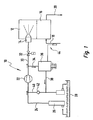
- a heating device 10 is first generally described described, for example, as an auxiliary heater, as auxiliary heater or the like in a vehicle can be used.
- the heating device 10 comprises one only schematically illustrated atomizer burner 12, in which means at least one atomizing nozzle 14 fuel is fed in atomized form becomes.
- a blower not shown, is assigned to the Feeded fuel combustion air introduced, so that in the atomizer burner 12 combustion can occur.
- heat exchanger 16 is in the atomizer burner 12 generated heat of combustion on a flowing through the heat exchanger 16 Medium, for example air to be heated or to be heated Water. This medium to be heated passes over a Inlet line 18 in the heat exchanger 16 and leaves it over an outlet line 20.
- a fuel pump 22 sucks via an intake line 24 and an Input area of this suction line 24 provided sieve 26 fuel from a fuel reservoir 28.
- Fuel pump 22 fuel under pressure to the atomizer nozzle 14.
- In the Pressure line 30 is a preferably electromagnetically adjustable valve 32 is provided, through which the fuel supply to the atomizing nozzle 14 can be interrupted in terms of quantity.
- a branch line 34 leads from the pressure line 30 to a downstream one Fuel pressure regulator 36 described in more detail.
- An exhaust line 38 leads from the fuel pressure regulator 36 back to the reservoir 28.
- a connecting line 40 between the outlet line 38 and the suction line 24 leading to the fuel pump 22 is a preferred one spring-loaded check valve or pressure valve 42 provided, which an inflow of fuel from the suction line 24 to Exhaust line 38 prevents, with appropriate pressure conditions however, an inflow of fuel from the outlet line 38 into the Suction line 24 allows.
- the check valve 42 can be set in this way that it opens when a pressure difference of 3 bar is applied.
- the check valve 42 opens when a pressure difference of 3 bar is applied.
- the fuel pressure regulator 36 is a sensor arrangement, generally designated 44 assigned. This records the temperature of the material to be heated Medium, for example in the inlet line 18, and feeds corresponding Information in the fuel pressure regulator 36. This in turn based on this information influences the pressure conditions in the Pressure line 30 or the branch line connected to this 34 and thus also the pressure of that directed to the atomizing nozzle 14 Fuel.
- the amount of gas through the atomizer nozzle 14 into the atomizer burner 12 fuel fed essentially depends on that existing fuel pressure in the pressure line 30, so that by Setting the same defines influence on the amount of in the atomizer burner 12 injected fuel can be taken.
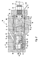
- a pressure regulator 36 according to the invention is as follows described in detail with reference to the accompanying Fig. 2.
- the pressure regulator 36 has a housing 46.
- One in the housing 46 formed opening 48 is substantially in an inner region 50 smooth surface while running in an outer area 52 is formed with an internal thread 54.
- In the area 50 is a sleeve-like provided cylinder element 56 which is basically in the direction an opening axis A is displaceable.
- O-ring-like sealing element 58 becomes fluid-tight in the direction of an opening base 60 Degree formed.
- the cylinder element points in an outer peripheral region 56 an extending over the entire circumference of the same Sink 62 on. In the area of this depression 62 opens into the opening 48 or the area 50 thereof penetrating the housing 46 Line section 64, which to the outlet line shown in Fig. 1 38 is connected or forms part of the same.
- the screw element 72 In the area 52 of the opening 48 there are two with an external thread 66 and 68, respectively provided screw elements 70, 72 screwed. Through the screw element 72, the opening 48 is closed to the outside. To this For purposes of use, the screw element 72 can protrude in the axial direction Have contact section 74, the corresponding screwing and tightening the screw member 72 for a fluid tight seal the opening 48 provides in this contact area.
- the screw element 72 also carries an adjustment screw 76 which has a head region 78 of the screw element 72 passes through and with this in threaded engagement stands. By means of a lock nut 80, the adjusting screw 76 can be of the screw element 72 can be set.
- a biasing spring is on the adjusting screw 76 via a support plate 82 84 supported.
- To also provide a fluid-tight seal here
- the support plate 82 provides a support surface 90 for the biasing spring 84 which through Rotation of the adjusting screw 76 is changeable in its axial position.
- the screw element 70 positioned further in the opening 48 forms a Abutment for an adjusting element 92, for example in the form of a ring.
- This adjusting element 92 is in the direction of the axis A between the Screw element 70 and the cylinder element 56 positioned.
- Another Preload spring 94 acts on the cylinder element 56 such that it is in fixed contact with the setting element 52 and thus this is held in fixed contact with the screw element 70.
- the bias spring 84 already mentioned passes through a central one Opening in the screw element 70 and a corresponding central opening in the adjusting element 92 and is supported in the axial direction on one in the Cylinder element 56 slidably received piston 96.
- the piston 96 is towards the opening bottom 60 biased and is in the state shown in Fig. 2 on this Opening base 60 supported.
- One opens into the opening bottom 60 further opening or a line section 97 at which the branch line 34 is connected or which is a part of this branch line 34 forms.
- a blind hole-like opening 98 is provided in association with the line section 97 there is 96 in the piston .
- first mouth area 102 to an outer peripheral surface of the piston 96 open.
- Openings or bores 104 are provided in the cylinder element 56 corresponding circumferential positions. These are radially outward open to the recess area 62 and are radially inward in one second mouth region 106 to an inner peripheral surface of the cylinder element 56 open.
- the mouth areas 102 or / and 106 can also be summarized by ring grooves, so that an exact circumferential alignment of openings 100 and 104 is not required.
- the setting element 92 forms part of the one which is already schematic in FIG. 1 addressed sensor arrangement, the information about the temperature of the medium to be heated feeds into the fuel pressure regulator 36.
- a heat transfer medium can be located over a heat exchanger area to one related to the temperature of the heating medium in the inlet line 18 standing temperature brought and by using a feed pump, not shown or the like. Is fed into the setting element 92 via a line connection 108 become. This passes through the head region 78 of the screw element 72 and extends along the internal thread 54 to the area the opening 48 in which the adjusting element 92 is positioned.
- the Adjustment element 92 can have a circulation area in which the medium flowing through line 108 circulates or which of is flowed through this medium.
- the setting element 92 partially or completely include material that occurs in the Temperature range has a defined thermal expansion behavior. It follows that, for example, when the line 108 flowing through Medium has a higher temperature, heat on it Part or all of the adjusting element 92 is transmitted and this itself then extends in the direction of axis A. The consequence of that is that too the cylinder element 56 counter to the biasing action of the biasing spring 94 in the direction of the opening bottom 60 to be moved, since that Screw element 70 is held immovably in the direction of the axis A. If the medium is cooled in line 108, it takes heat from Adjustment element 92 on, with the result that this contract will and will have a shorter axial length.
- the cylinder element 56 can also move axially again, and in the direction away from the opening base 60.
- the consequence of this thermally conditional change in length of the adjusting element 92 and the associated Displacement of the cylinder member 56 is that in the piston 96 provided openings 100 with their first mouth areas 102 with respect to the openings 104 provided in the cylinder element 56 their second mouth regions 106 shifted in the direction of the axis A. become.
- This relative shift also changes the overlap of the mouth areas 102, 106 and thus also in the area of the mutual connection of these mouth areas 102, 106 formed Throttling effect in the transition area between the line sections or openings 97 and 64 and thus the lines shown in FIG. 1 34 and 38.
- the fuel pump 22 is operated in such a way that it has a plateau area in its production curve achieved, which means that by increasing the speed of a pump drive motor a further increase in output essentially does not occur.
- This drive motor not shown, also drives at the same time a combustion air blower so that in this working state the Fuel feed pump 22 changes the speed of the drive motor cannot induce a change in the combustion air flow rate however, can induce a change in fuel flow. This has As a result, the fuel feed pump basically works in such a way that regardless of the operation of the fuel pressure regulator 36, it is in the pressure line 30 can provide the maximum possible pressure.
- the temperature of the medium to be heated is therefore the one fed in Amount of fuel in the atomizing burner 12 increases, which is an increase in Heating output of the same.
- Fuel feed quantity can also be the speed of the drive motor increased for the fuel feed pump 22 and the combustion air blower in order to be assigned to the increased fuel injection quantity to be able to provide a correspondingly increased amount of combustion air.
- a further sensor arrangement which the temperature of the medium to be heated in the range of Inlet line detected, and corresponding control electronics in assignment an increased delivery rate for the effect of the fuel pressure regulator 36 of the combustion air blower is generated.
- FIG. 4 A modified embodiment of a fuel pressure regulator according to the invention is shown in Figures 4 and 5.
- components which components described above with regard to structure or Function correspond, are added with the same reference numerals of an appendix "a”.
- this is sleeve-like trained cylinder element 56a between the opening bottom 60a and the screw element 70a held axially fixed.
- the piston 96a stands still under the bias of the bias spring 84a, which is at the other end via the support plate 82a and an adjusting element 92a on the adjusting screw 76a in the direction of the axis A.
- the bias spring 84a Depending on those in the pressure line 30 or the branch line 34 prevailing pressure conditions becomes the piston which is acted upon by the line pressure 96a and on the other hand pistons 96a acted upon by the biasing spring 84a adopt an equilibrium position in which there is a certain overlap the mouth areas 102a, 106a will adjust.
- the setting element 92a has one comparatively short axial length, so that the support surface 90a for the biasing spring 84a from the opening bottom 60a comparatively is moved far away and in this respect the biasing spring 84a is only a smaller one Will produce biasing effect. As a result, if there is one Fuel pressure a comparatively large overlap of the mouth areas 102a, 106a can be obtained.
- the setting element 92a changes, as in FIG Transition to Fig. 5 recognizable, its axial length.
- the support surface 90a of the plate 82a axially displaced, namely in the direction towards the opening bottom 60a.
- the spring 84a is compressed more and so far will produce a greater bias.
- the Piston 96a continues to move toward orifice bottom 60a, causing the overlap between the mouth areas 102a and 106a is reduced becomes.
- This reduction in the overlap in turn means that a lower proportion of the fuel fed into the pressure line 30 can drain the fuel pressure regulator 36a, whereby the pressure in the Pressure line 30 will rise and a larger via the atomizing nozzle 14 Amount of fuel is fed into the atomizer burner 12.
- setting element 92a for example, as by Fluid supply configured in its axial length pad element can be, this fluid supply through a provided for this Fluid pump can be done.
- This fluid pump can in turn be dependent the temperature present in the area of the inlet line 18, for example detected by a temperature sensor for the supply of Print medium in the cushion-like or cushion-like setting element 92a are driven, or it can be, for example, by a corresponding Opening a valve assembly pressure medium from the setting element 92a to reduce the axial extent of the same.
- the temperature of the material to be heated can Medium in the area of the inlet line 18 are implemented in a certain axial length of an adjusting element.
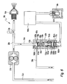
- FIG. 6 shows a further embodiment of an inventive one Heater shown.
- Components described above Components correspond in terms of structure and function with the same reference numerals with the addition of an appendix "b" designated.
- the basic structure of the system 10b shown in FIG. 6 corresponds to that previously described with reference to FIG. 1. It is therefore on those that exist primarily in the area of the fuel pressure regulator 36b Differences entered.
- the fuel pressure regulator shown in Fig. 6 36b again comprises the piston 96b as a pressure regulating element, which by the Fuel pressure on the one hand and the biasing spring 84b on the other hand is.
- the Piston 96b moved so far away from the opening bottom 60b that none or only a slight overlap with the opening or openings 104b or the channels formed in these areas is present.
- the one in the area of these openings or channels 104b is then a throttling effect low, so that a large amount of fuel will flow away.
- the biasing force of the spring 84b is sufficient to a larger, for example, complete coverage of the openings To reach 104b with the piston 96b.
- the support plate is 82b supported on a piston element 152b.
- This piston element 152b is in an inner housing member 154b slidably received, which Inner housing element 154b in turn in a housing 36b, for example insert element 156b held by thread engagement.
- This insert element 156b can also be an axial stop for form the support plate 82b.
- the piston element 152b At its other end is the piston element 152b with the interposition of a membrane 158b in contact with an expansion element 160b still described with regard to its function.
- the expansion element 160b is again in contact with one designated 162b Heating device. This includes a heatable by energization Resistance heating element 164b, which is embedded in a carrier body 166b is.
- This carrier body 166b or the heating device 162b is shown in FIG the screw element 72b.
- the heater 162b is under Activation of a control device 168b, which at the same time also in Connected to a temperature sensor 44b. This can, for example immerse in the liquid to be heated and its temperature detect so that in the control device 168b information about the heating liquid is present. According to this present Information is then triggered by appropriate control of the control device 168b the heating device 162b is more or less strongly excited or be warmed. According to the temperature of the heater 162b the expansion element 160b heated by this becomes its dimension change, due to the outward expansion restriction a volume change essentially towards the Opening floor 60b to or from this will take place.
- the temperature is adjusted of the medium to be heated, the preload of the preload spring 84b changed to achieve a defined outflow, so that an influence to the pressure control characteristic of the fuel pressure regulator 36b can be taken.
- a higher heating capacity i. H. is a high fuel pressure is required by appropriate Energizing the heater 162b an expansion of the expansion element 160b and an associated displacement of the piston element 152b generated. With this shift, the piston also becomes 96b in the direction of the opening base 60b, so that a there is greater coverage of the opening or openings 104b becomes.
- a lower required heating output, for example at higher temperature of the liquid to be heated has a corresponding Actuation of the heater 162b as a result of contraction of the expansion element 160b reduces the pretension of the spring 84b or the support surface 90b for piston 60b this is withdrawn.
- control device 168b Since the control device 168b has information about it, in to what extent the heating output is to be changed or which heating output is required, it can also be used at the same time Drive motor for the combustion air blower in accordance with the Specify a specific fuel injection amount to control at higher fuel pressure, i.e. with higher required heating output, too to feed more combustion air into a combustion chamber.
- Pistons 96 and 96a shown can be constructed as shown in Fig. 6.
Landscapes
- Engineering & Computer Science (AREA)
- Chemical & Material Sciences (AREA)
- Combustion & Propulsion (AREA)
- Mechanical Engineering (AREA)
- General Engineering & Computer Science (AREA)
- Feeding And Controlling Fuel (AREA)
- Air-Conditioning For Vehicles (AREA)
- Pressure-Spray And Ultrasonic-Wave- Spray Burners (AREA)
Abstract
Description
- Fig. 1
- eine Prinzipansicht einer Heizeinrichtung mit einem erfindungsgemäßen Brennstoffdruckregler;
- Fig. 2
- eine Längsschnittansicht eines erfindungsgemäßen Druckreglers in einem Zustand mit geringerer geforderter Heizleistung;
- Fig. 3
- eine der Fig. 2 entsprechende Ansicht des Druckreglers in einem Zustand mit größerer geforderter Heizleistung;
- Fig. 4
- eine Längsschnittansicht eines weiteren erfindungsgemäßen Druckreglers in einem Zustand mit geringerer geforderter Heizleistung;
- Fig. 5
- den in Fig. 4 dargestellten Druckregler in einem Zustand mit größerer geforderter Heizleistung;
- Fig. 6
- eine der Fig. 1 entsprechende Ansicht einer Heizeinrichtung mit einem alternativ ausgestalteten Brennstoffdruckregler.
Claims (17)
- Brennstoffdruckregler, insbesondere für einen Zerstäuberbrenner für ein Fahrzeugheizgerät, umfassend ein Druckregelorgan (96; 96a; 96b), dessen Regelwirkung in Abhängigkeit von einer geforderten Heizleistung veränderbar ist.
- Brennstoffdruckregler nach Anspruch 1,
dadurch gekennzeichnet, dass die geforderte Heizleistung im Wesentlichen bestimmt ist durch die Temperatur eines zu erwärmenden Mediums. - Brennstoffdruckregler nach Anspruch 1 oder 2,
dadurch gekennzeichnet, dass das Druckregelorgan (96; 96a; 96b) durch den im Brennstoff vorherrschenden Brennstoffdruck gegen die Vorspannwirkung einer ersten Rückstellanordnung (84; 84a; 96b) beaufschlagt ist, so dass sich eine Brennstoffabflussmenge aus einem Brennstoff enthaltenden Raumbereich (30, 34) einstellt. - Brennstoffdruckregler nach Anspruch 3,
dadurch gekennzeichnet, dass das Druckregelorgan (96; 96a; 96b) einen in einem Zylinderelement (56; 56a; 46b) verlagerbaren und durch den Brennstoffdruck einerseits und von der ersten Rückstellanordnung (84; 84a; 84b) andererseits beaufschlagten Kolben (96; 96a; 96b) umfasst, durch welchen in Abhängigkeit vom Brennstoffdruck eine in dem Zylinderelement (56; 56a; 46b) vorgesehene Kanalanordnung (104; 104a; 104b) überdeckbar ist. - Brennstoffdruckregler nach Anspruch 4,
dadurch gekennzeichnet, dass in dem Kolben (96; 96a) eine erste Kanalanordnung (100; 100a) vorgesehen ist, welche zu dem Brennstoff enthaltenden Raumbereich (30, 34) offen ist und in einem ersten Mündungsbereich (102; 102a) zu einer Außenumfangsfläche des Kolbens (96; 96a) offen ist, dass in dem Zylinderelement (56; 56a) eine zweite Kanalanordnung (104; 104a) ausgebildet ist, die in einem zweiten Mündungsbereich (106; 106a) zu einer Innenumfangsfläche des Zylinderelements (56; 56a) offen ist, und dass durch Relativbewegung (96; 96a) zwischen Kolben und Zylinderelement (56; 56a) ein Überlapp des ersten Mündungsbereichs (102; 102a) mit dem zweiten Mündungsbereich (106; 106a) veränderbar ist. - Brennstoffdruckregler nach Anspruch 5,
dadurch gekennzeichnet, dass durch zunehmenden Brennstoffdruck der Kolben (96; 96a) in Richtung Vergrößerung des Überlapps des ersten Mündungsbereichs (102; 102a) mit dem zweiten Mündungsbereich (106; 106a) beaufschlagbar ist. - Brennstoffdruckregler nach einem der Ansprüche 3 bis 6,
dadurch gekennzeichnet, dass die Vorspannwirkung der ersten Rückstellanordnung (84; 84a; 84b) mit zunehmender geforderter Heizleistung zunimmt. - Brennstoffdruckregler nach Anspruch 5 und Anspruch 7,
dadurch gekennzeichnet, dass durch zunehmende Vorspannwirkung der ersten Rückstellanordnung (84; 84a) der Kolben (96; 96a) in Richtung Verringerung des Überlapps des ersten Mündungsbereichs (102; 102a) mit dem zweiten Mündungsbereich (106; 106a) beaufschlagbar ist. - Brennstoffdruckregler nach einem der Ansprüche 3 bis 8,
dadurch gekennzeichnet, dass die erste Rückstellanordnung (84; 84a; 84b) eine Rückstellfeder (84; 84a; 84b) umfasst, deren Vorspannung in Abhängigkeit von der geforderten Heizleistung veränderbar ist. - Brennstoffdruckregler nach Anspruch 9, sofern auf Anspruch 4 rückbezogen,
dadurch gekennzeichnet, dass die Rückstellfeder (84a; 84b) bezüglich des Kolbens (96a; 96a) einerseits und bezüglich einer Abstützanordnung (82a, 92a; 82b, 152b, 160b) andererseits abgestützt ist und dass ein durch die Abstützanordnung (82a, 92a; 82b, 152b, 160b) für die Rückstellfeder (84a; 84b) bereitgestellter Abstützbereich (90a; 90b) in Abhängigkeit von der geforderten Heizleistung verlagerbar ist. - Brennstoffdruckregler nach Anspruch 10,
dadurch gekennzeichnet, dass die Abstützanordnung (82b, 152b, 160b) ein durch Temperaturänderung in seiner Außenabmessung veränderbares Dehnelement (160b) umfasst. - Brennstoffdruckregler nach einem der Ansprüche 3 bis 8,
dadurch gekennzeichnet, dass das Zylinderelement (56) in Abhängigkeit von der geforderten Heizleistung bezüglich eines Gehäuses (46) verlagerbar ist. - Brennstoffdruckregler nach Anspruch 12,
dadurch gekennzeichnet, dass das Zylinderelement (56) mit zunehmender geforderter Heizleistung in Richtung Verringerung des Überlapps des ersten Mündungsbereichs (102) mit dem zweiten Mündungsbereich (106) verlagerbar ist. - Brennstoffdruckregler nach Anspruch 12 oder 13,
dadurch gekennzeichnet, dass das Zylinderelement (56) von einem Einstellelement (92) in Abhängiggkeit von der geforderten Heizleistung gegen die Wirkung einer zweiten Rückstellanordnung (94) beaufschlagbar ist. - Brennstoffdruckregler nach Anspruch 14,
dadurch gekennzeichnet, dass eine Abmessung des Einstellelements (92) in Abhängigkeit von der geforderten Heizleistung einstellbar ist. - Heizeinrichtung, insbesondere für ein Fahrzeug, umfassend einen Zerstäuberbrenner (12) mit wenigstens einer Zerstäuberdüse (14), eine Brennstoffpumpanordnung (22) zum Fördern von Brennstoff von einem Brennstoffreservoir (28) zu der wenigstens einen Zerstäuberdüse (14) sowie einen Brennstoffdruckregler (36; 36a; 36b) nach einem der vorangehenden Ansprüche zur Druckeinstellung in einem Leitungsbereich (30) zwischen der Brennstoffpumpanordnung (22) und der wenigstens einen Zerstäuberdüse (14).
- Heizeinrichtung nach Anspruch 16,
gekennzeichnet durch eine Luftförderanordnung zum Fördern von Verbrennungsluft in einen Verbrennungsraum, wobei eine Förderleistung der Luftförderanordnung in Übereinstimmung mit einer Veränderung der Regelwirkung des Druckregelorgans zur Anpassung der in den Brennraum eingeleiteten Verbrennungsluftmenge veränderbar ist.
Applications Claiming Priority (2)
| Application Number | Priority Date | Filing Date | Title |
|---|---|---|---|
| DE10230401 | 2002-07-05 | ||
| DE10230401A DE10230401A1 (de) | 2002-07-05 | 2002-07-05 | Brennstoffdruckregler, insbesondere für einen Zerstäuberbrenner für ein Fahrzeugheizgerät |
Publications (3)
| Publication Number | Publication Date |
|---|---|
| EP1378710A2 true EP1378710A2 (de) | 2004-01-07 |
| EP1378710A3 EP1378710A3 (de) | 2004-08-04 |
| EP1378710B1 EP1378710B1 (de) | 2011-01-26 |
Family
ID=29719489
Family Applications (1)
| Application Number | Title | Priority Date | Filing Date |
|---|---|---|---|
| EP03009190A Expired - Lifetime EP1378710B1 (de) | 2002-07-05 | 2003-04-22 | Brennstoffdruckregler für einen Zerstäuberbrenner eines Fahrzeugheizgeräts |
Country Status (2)
| Country | Link |
|---|---|
| EP (1) | EP1378710B1 (de) |
| DE (2) | DE10230401A1 (de) |
Cited By (3)
| Publication number | Priority date | Publication date | Assignee | Title |
|---|---|---|---|---|
| WO2006050824A1 (de) * | 2004-11-10 | 2006-05-18 | Daimlerchrysler Ag | Kraftstoffversorgungssystem für ein heizgerät eines kraftfahrzeugs |
| WO2007134580A1 (de) * | 2006-05-19 | 2007-11-29 | Ulrich Dreizler | Flammenmodellierung |
| EP2199678A3 (de) * | 2008-12-19 | 2011-12-14 | J. Eberspächer GmbH & Co. KG | Brenner eines Fahrzeugheizgerätes |
Families Citing this family (1)
| Publication number | Priority date | Publication date | Assignee | Title |
|---|---|---|---|---|
| CN104329685A (zh) * | 2014-09-26 | 2015-02-04 | 南京英达公路养护车制造有限公司 | 一种变压火力调节装置 |
Family Cites Families (5)
| Publication number | Priority date | Publication date | Assignee | Title |
|---|---|---|---|---|
| DE3303915C2 (de) * | 1983-02-05 | 1986-09-18 | Danfoss A/S, Nordborg | Mengenregelvorrichtung für einen Ölbrenner |
| DE3636647A1 (de) * | 1986-10-28 | 1988-05-19 | Danfoss As | Heizoelpumpe fuer wahlweisen ein- oder zweistrang-betrieb |
| DE3808397A1 (de) * | 1988-03-12 | 1989-10-19 | Eberspaecher J | Druckregler |
| DE4329955C2 (de) * | 1993-09-04 | 1997-01-16 | Danfoss As | Pumpenanordnung für einen Ölbrenner und Verfahren zur Kapazitätsregelung dieses Ölbrenners |
| DE19645180A1 (de) * | 1996-11-02 | 1998-05-07 | Eberspaecher J Gmbh & Co | Druckzerstäuberbrenner für ein motorunabhängiges Fahrzeugheizgerät |
-
2002
- 2002-07-05 DE DE10230401A patent/DE10230401A1/de not_active Withdrawn
-
2003
- 2003-04-22 EP EP03009190A patent/EP1378710B1/de not_active Expired - Lifetime
- 2003-04-22 DE DE50313431T patent/DE50313431D1/de not_active Expired - Lifetime
Cited By (4)
| Publication number | Priority date | Publication date | Assignee | Title |
|---|---|---|---|---|
| WO2006050824A1 (de) * | 2004-11-10 | 2006-05-18 | Daimlerchrysler Ag | Kraftstoffversorgungssystem für ein heizgerät eines kraftfahrzeugs |
| WO2007134580A1 (de) * | 2006-05-19 | 2007-11-29 | Ulrich Dreizler | Flammenmodellierung |
| EP2199678A3 (de) * | 2008-12-19 | 2011-12-14 | J. Eberspächer GmbH & Co. KG | Brenner eines Fahrzeugheizgerätes |
| US8695569B2 (en) | 2008-12-19 | 2014-04-15 | Bosch Emission Systems Gmbh & Co. Kg | Vehicle burner |
Also Published As
| Publication number | Publication date |
|---|---|
| EP1378710A3 (de) | 2004-08-04 |
| DE10230401A1 (de) | 2004-01-22 |
| DE50313431D1 (de) | 2011-03-10 |
| EP1378710B1 (de) | 2011-01-26 |
Similar Documents
| Publication | Publication Date | Title |
|---|---|---|
| DE60125830T2 (de) | Druckregulator | |
| DE2354352A1 (de) | Pumpe | |
| DE2638736C3 (de) | Kraftstoffeinspritzpumpe für Brennkraftmaschinen mit hydraulischem Regler | |
| DE3118003C2 (de) | Thermostatgesteuerter Mischer für Kalt- und Heißwasser | |
| DE2608791C2 (de) | ||
| EP0061415A1 (de) | Ventil für hydraulische Systeme | |
| EP1209349B1 (de) | Kraftstoffeinspritzsystem mit Kraftstoffvorwärmung und kraftstoffgekühltem Druckregelventil | |
| DE68912995T2 (de) | Kraftstoffeinspritzventil. | |
| EP1809932A1 (de) | Thermostatischer mischer mit vorrichtung zur dynamischen regelung eines wasserflusses | |
| DE602004003796T2 (de) | Gaszuführsystem für eine Brennkraftmaschine mit verbessertem Druckregler | |
| EP1378710B1 (de) | Brennstoffdruckregler für einen Zerstäuberbrenner eines Fahrzeugheizgeräts | |
| DE10153459A1 (de) | Anordnung zur Steuerung des Kühlfluidstroms in Kompressoren | |
| DE3309301A1 (de) | Kleinoelbrenner | |
| DE10241461A1 (de) | Volumenstromregelventil | |
| EP1810103B1 (de) | Vorrichtung zur dynamischen regelung eines wasserflusses | |
| DE19848904A1 (de) | Druckstufe zur Regulierung einer Voreinspritzmenge von Kraftstoff in Verbrennungsmotoren, vorzugsweise in Dieselmotoren | |
| DE10261634B4 (de) | Kombinationsverschraubung für eine Vorrichtung zur Regelung des Flusses von Druckflüssigkeit in einer Durchfluss-Kontrolleinrichtung | |
| DE3041080A1 (de) | Kraftstoffeinspritzpumpe fuer mehrzylinder-brennkraftmaschinen | |
| DE10327575A1 (de) | Kraftstoffzuführanlage und Druckregelventil hierfür | |
| DE3203583A1 (de) | Kraftstoffeinspritzpumpe fuer brennkraftmaschinen mit spritzzeitpunktverstellung | |
| DE19923422C2 (de) | Elektronisches Einspritzsystem | |
| DE3510221A1 (de) | Kraftstoffeinspritzpumpe fuer brennkraftmaschinen | |
| DE3407747A1 (de) | Druckregler fuer eine verstellbare pumpe | |
| EP1694965B1 (de) | Summenleistungsregelvorrichtung | |
| EP1251277B1 (de) | Druckmittler und Leistungsregelvorrichtung |
Legal Events
| Date | Code | Title | Description |
|---|---|---|---|
| PUAI | Public reference made under article 153(3) epc to a published international application that has entered the european phase |
Free format text: ORIGINAL CODE: 0009012 |
|
| AK | Designated contracting states |
Kind code of ref document: A2 Designated state(s): AT BE BG CH CY CZ DE DK EE ES FI FR GB GR HU IE IT LI LU MC NL PT RO SE SI SK TR |
|
| AX | Request for extension of the european patent |
Extension state: AL LT LV MK |
|
| PUAL | Search report despatched |
Free format text: ORIGINAL CODE: 0009013 |
|
| AK | Designated contracting states |
Kind code of ref document: A3 Designated state(s): AT BE BG CH CY CZ DE DK EE ES FI FR GB GR HU IE IT LI LU MC NL PT RO SE SI SK TR |
|
| AX | Request for extension of the european patent |
Extension state: AL LT LV MK |
|
| RIC1 | Information provided on ipc code assigned before grant |
Ipc: 7F 23D 11/30 A Ipc: 7F 23N 1/00 B Ipc: 7F 23K 5/14 B |
|
| 17P | Request for examination filed |
Effective date: 20040830 |
|
| AKX | Designation fees paid |
Designated state(s): CZ DE FR GB SE TR |
|
| RBV | Designated contracting states (corrected) |
Designated state(s): CZ DE FR GB SE TR |
|
| 17Q | First examination report despatched |
Effective date: 20060308 |
|
| GRAP | Despatch of communication of intention to grant a patent |
Free format text: ORIGINAL CODE: EPIDOSNIGR1 |
|
| GRAS | Grant fee paid |
Free format text: ORIGINAL CODE: EPIDOSNIGR3 |
|
| GRAA | (expected) grant |
Free format text: ORIGINAL CODE: 0009210 |
|
| AK | Designated contracting states |
Kind code of ref document: B1 Designated state(s): CZ DE FR GB SE TR |
|
| REG | Reference to a national code |
Ref country code: GB Ref legal event code: FG4D Free format text: NOT ENGLISH |
|
| REF | Corresponds to: |
Ref document number: 50313431 Country of ref document: DE Date of ref document: 20110310 Kind code of ref document: P |
|
| REG | Reference to a national code |
Ref country code: DE Ref legal event code: R096 Ref document number: 50313431 Country of ref document: DE Effective date: 20110310 |
|
| REG | Reference to a national code |
Ref country code: SE Ref legal event code: TRGR |
|
| REG | Reference to a national code |
Ref country code: SE Ref legal event code: EUG |
|
| PG25 | Lapsed in a contracting state [announced via postgrant information from national office to epo] |
Ref country code: CZ Free format text: LAPSE BECAUSE OF FAILURE TO SUBMIT A TRANSLATION OF THE DESCRIPTION OR TO PAY THE FEE WITHIN THE PRESCRIBED TIME-LIMIT Effective date: 20110126 |
|
| PLBE | No opposition filed within time limit |
Free format text: ORIGINAL CODE: 0009261 |
|
| STAA | Information on the status of an ep patent application or granted ep patent |
Free format text: STATUS: NO OPPOSITION FILED WITHIN TIME LIMIT |
|
| GBPC | Gb: european patent ceased through non-payment of renewal fee |
Effective date: 20110426 |
|
| 26N | No opposition filed |
Effective date: 20111027 |
|
| REG | Reference to a national code |
Ref country code: FR Ref legal event code: ST Effective date: 20111230 |
|
| PG25 | Lapsed in a contracting state [announced via postgrant information from national office to epo] |
Ref country code: FR Free format text: LAPSE BECAUSE OF NON-PAYMENT OF DUE FEES Effective date: 20110502 |
|
| REG | Reference to a national code |
Ref country code: DE Ref legal event code: R097 Ref document number: 50313431 Country of ref document: DE Effective date: 20111027 |
|
| PG25 | Lapsed in a contracting state [announced via postgrant information from national office to epo] |
Ref country code: GB Free format text: LAPSE BECAUSE OF NON-PAYMENT OF DUE FEES Effective date: 20110426 |
|
| PG25 | Lapsed in a contracting state [announced via postgrant information from national office to epo] |
Ref country code: SE Free format text: LAPSE BECAUSE OF NON-PAYMENT OF DUE FEES Effective date: 20110423 |
|
| REG | Reference to a national code |
Ref country code: DE Ref legal event code: R082 Ref document number: 50313431 Country of ref document: DE Representative=s name: WEICKMANN & WEICKMANN, DE |
|
| REG | Reference to a national code |
Ref country code: DE Ref legal event code: R082 Ref document number: 50313431 Country of ref document: DE Representative=s name: WEICKMANN & WEICKMANN, DE Effective date: 20130607 Ref country code: DE Ref legal event code: R081 Ref document number: 50313431 Country of ref document: DE Owner name: EBERSPAECHER CLIMATE CONTROL SYSTEMS GMBH & CO, DE Free format text: FORMER OWNER: J. EBERSPAECHER GMBH & CO. KG, 73730 ESSLINGEN, DE Effective date: 20130607 Ref country code: DE Ref legal event code: R082 Ref document number: 50313431 Country of ref document: DE Representative=s name: RUTTENSPERGER LACHNIT TROSSIN GOMOLL PATENT- U, DE Effective date: 20130607 Ref country code: DE Ref legal event code: R082 Ref document number: 50313431 Country of ref document: DE Representative=s name: RUTTENSPERGER LACHNIT TROSSIN GOMOLL, PATENT- , DE Effective date: 20130607 |
|
| PG25 | Lapsed in a contracting state [announced via postgrant information from national office to epo] |
Ref country code: TR Free format text: LAPSE BECAUSE OF FAILURE TO SUBMIT A TRANSLATION OF THE DESCRIPTION OR TO PAY THE FEE WITHIN THE PRESCRIBED TIME-LIMIT Effective date: 20110126 |
|
| REG | Reference to a national code |
Ref country code: DE Ref legal event code: R082 Ref document number: 50313431 Country of ref document: DE Representative=s name: RUTTENSPERGER LACHNIT TROSSIN GOMOLL PATENT- U, DE Ref country code: DE Ref legal event code: R082 Ref document number: 50313431 Country of ref document: DE Representative=s name: RUTTENSPERGER LACHNIT TROSSIN GOMOLL, PATENT- , DE |
|
| PGFP | Annual fee paid to national office [announced via postgrant information from national office to epo] |
Ref country code: DE Payment date: 20150430 Year of fee payment: 13 |
|
| REG | Reference to a national code |
Ref country code: DE Ref legal event code: R119 Ref document number: 50313431 Country of ref document: DE |
|
| PG25 | Lapsed in a contracting state [announced via postgrant information from national office to epo] |
Ref country code: DE Free format text: LAPSE BECAUSE OF NON-PAYMENT OF DUE FEES Effective date: 20161101 |