EP1375757B1 - Baumaschine mit Werkzeugschnellkupplung und Identifikationssystem für das zu kuppelnde Werkzeug - Google Patents
Baumaschine mit Werkzeugschnellkupplung und Identifikationssystem für das zu kuppelnde Werkzeug Download PDFInfo
- Publication number
- EP1375757B1 EP1375757B1 EP03013258A EP03013258A EP1375757B1 EP 1375757 B1 EP1375757 B1 EP 1375757B1 EP 03013258 A EP03013258 A EP 03013258A EP 03013258 A EP03013258 A EP 03013258A EP 1375757 B1 EP1375757 B1 EP 1375757B1
- Authority
- EP
- European Patent Office
- Prior art keywords
- tool
- coupling
- boom
- construction machine
- quick coupling
- Prior art date
- Legal status (The legal status is an assumption and is not a legal conclusion. Google has not performed a legal analysis and makes no representation as to the accuracy of the status listed.)
- Expired - Lifetime
Links
- 238000010168 coupling process Methods 0.000 claims description 24
- 230000008878 coupling Effects 0.000 claims description 23
- 238000005859 coupling reaction Methods 0.000 claims description 23
- 238000010276 construction Methods 0.000 claims description 21
- 238000000034 method Methods 0.000 claims description 2
- 239000003921 oil Substances 0.000 description 6
- 230000005540 biological transmission Effects 0.000 description 1
- 230000006378 damage Effects 0.000 description 1
- 230000006870 function Effects 0.000 description 1
- 239000010720 hydraulic oil Substances 0.000 description 1
- 230000007257 malfunction Effects 0.000 description 1
- 238000003801 milling Methods 0.000 description 1
Images
Classifications
-
- E—FIXED CONSTRUCTIONS
- E02—HYDRAULIC ENGINEERING; FOUNDATIONS; SOIL SHIFTING
- E02F—DREDGING; SOIL-SHIFTING
- E02F3/00—Dredgers; Soil-shifting machines
- E02F3/04—Dredgers; Soil-shifting machines mechanically-driven
- E02F3/28—Dredgers; Soil-shifting machines mechanically-driven with digging tools mounted on a dipper- or bucket-arm, i.e. there is either one arm or a pair of arms, e.g. dippers, buckets
- E02F3/36—Component parts
- E02F3/3604—Devices to connect tools to arms, booms or the like
- E02F3/3609—Devices to connect tools to arms, booms or the like of the quick acting type, e.g. controlled from the operator seat
- E02F3/3654—Devices to connect tools to arms, booms or the like of the quick acting type, e.g. controlled from the operator seat with energy coupler, e.g. coupler for hydraulic or electric lines, to provide energy to drive(s) mounted on the tool
-
- E—FIXED CONSTRUCTIONS
- E02—HYDRAULIC ENGINEERING; FOUNDATIONS; SOIL SHIFTING
- E02F—DREDGING; SOIL-SHIFTING
- E02F9/00—Component parts of dredgers or soil-shifting machines, not restricted to one of the kinds covered by groups E02F3/00 - E02F7/00
- E02F9/20—Drives; Control devices
- E02F9/22—Hydraulic or pneumatic drives
- E02F9/2221—Control of flow rate; Load sensing arrangements
-
- E—FIXED CONSTRUCTIONS
- E02—HYDRAULIC ENGINEERING; FOUNDATIONS; SOIL SHIFTING
- E02F—DREDGING; SOIL-SHIFTING
- E02F9/00—Component parts of dredgers or soil-shifting machines, not restricted to one of the kinds covered by groups E02F3/00 - E02F7/00
- E02F9/20—Drives; Control devices
- E02F9/22—Hydraulic or pneumatic drives
- E02F9/2264—Arrangements or adaptations of elements for hydraulic drives
- E02F9/2271—Actuators and supports therefor and protection therefor
-
- E—FIXED CONSTRUCTIONS
- E02—HYDRAULIC ENGINEERING; FOUNDATIONS; SOIL SHIFTING
- E02F—DREDGING; SOIL-SHIFTING
- E02F9/00—Component parts of dredgers or soil-shifting machines, not restricted to one of the kinds covered by groups E02F3/00 - E02F7/00
- E02F9/26—Indicating devices
Definitions
- the invention relates to a construction machine with quick coupling for coupling a tool to a boom according to the preamble of claim 1.
- the construction machinery such as hydraulic excavators
- hydraulic excavators are equipped with very different tools, such as with buckets, shovels, grippers, hammers, shears, milling, fangs, hooks and much more.
- wheel loaders and other construction machinery which have corresponding boom, can be used.
- multifunctional machines by the use of different tools.
- the transmission of the kinematics data may cause a collision, e.g. be prevented with the cabin or overhead lines, etc.
- a control device and a control method for a construction machine is known.
- a memory for identification data for the tool is provided to identify a conventionally attached tool in the tool.
- the data stored in memory are transmitted to a control unit in the construction machine.
- the tool must be connected to the construction machine not only hydraulically but also electrically.
- the object of the invention is therefore to develop a construction machine with quick coupling such that technical or safety risks in automatic Coupling a tool to a construction machine safely prevented and the function is properly guaranteed.
- an identification system which includes on the one hand on the tool side as means for identifying the type, size, weight and dimension, the tool a transponder and the construction machine side means for reading and processing the tool-related information.
- this identification system can be communicated in the first step in the cultivation of the tool of the construction machine on the corresponding identification system, which tool was grown, d. H. what weight and what content of the possibly attached backhoe, what oil quantity and which oil pressure the tool needs to operate or what dimensions the tool has.
- the data is transmitted to the on-board computer, which then makes it available, for example, to the hydraulic pump for setting the correct amount and the pressure of the hydraulic oil. From the transmitted weights and dimensions, the available payload can be determined and displayed. Furthermore, the possible range, digging depth and height can be displayed or fed as limit values into the control of the boom.
- the transponder interacts with the construction-machine-side means for reading and processing the information. These are preferably part of the on-board computer or they are at least connected to this.
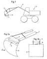
- Fig. 1 as a construction machine by way of example a hydraulic excavator 10 is shown, on the boom 12, a tool changer 14 is grown with energy conduction. This executed as a quick coupler tool changer 14 can accommodate any tool 16 automatically, at the same time the power circuit, for example, in the present example, the hydraulic circuit is coupled when receiving the tool 16.
- a spoon 16 attached to a hydraulic excavator boom is shown in FIGS. 2a and 2b respectively.
- This spoon 16 has a tool-side means 18 for identifying the type and size of the tool in the form of a transponder.
- This transponder 18 communicates with the cultivation of the spoon 16 to the on-board computer of the hydraulic excavator 10, not shown here, with what the weight of the spoon is and what content this has. Furthermore, the dimensions of the spoon 16 are forwarded to the on-board computer. In a memory of the on-board computer, which is likewise not shown here, the oil quantities or pressure ratios necessary for the attached spoon are stored for the hydraulic circuit.
Landscapes
- Engineering & Computer Science (AREA)
- Mining & Mineral Resources (AREA)
- Civil Engineering (AREA)
- General Engineering & Computer Science (AREA)
- Structural Engineering (AREA)
- Mechanical Engineering (AREA)
- Physics & Mathematics (AREA)
- Fluid Mechanics (AREA)
- Operation Control Of Excavators (AREA)
- Shovels (AREA)
- Soil Working Implements (AREA)
- Quick-Acting Or Multi-Walled Pipe Joints (AREA)
- Earth Drilling (AREA)
- Conveying And Assembling Of Building Elements In Situ (AREA)
- Component Parts Of Construction Machinery (AREA)
- Automatic Tool Replacement In Machine Tools (AREA)
Description
- Die Erfindung betrifft eine Baumaschine mit Schnellkupplung zum Ankuppeln eines Werkzeuges an einen Ausleger nach dem Oberbegriff des Anspruchs 1.
- Es sind bereits Baumaschinen mit Schnellkupplung zum Ankuppeln eines Werkzeuges an einen Ausleger bekannt. So weist beispielsweise die
DE 31 35 150 C1 einen auslegerseitigen Schnellkupplungsteil und einen werkzeugseitigen Schnellkupplungsteil mit einer Energiekreiskupplung auf. Bei Hydraulikbaggern werden als Energiekreiskupplung Hydraulikkupplungen verwendet. Mit den bekannten Schnellkupplungen ist ein automatisches Ankuppeln des Werkzeuges möglich, wobei der werkzeugseitige Energieanschluß an den entsprechenden auslegerseitigen Energieanschluß ebenfalls automatisch gekoppelt wird. - Die Baumaschinen, beispielsweise Hydraulikbagger, werden mit sehr unterschiedlichen Werkzeugen bestückt, beispielsweise mit Tieflöffeln, Schaufeln, Greifern, Hämmern, Scheren, Fräsen, Reißzähnen, Lasthaken und vieles mehr. Neben dem vorgenannten Hydraulikbagger sind aber auch Radlader und andere Baumaschinen, die entsprechende Ausleger aufweisen, einsetzbar. Neben ihrer typischen Verwendung sind diese Baumaschinen durch den Anbau von verschiedenen Werkzeugen zu Multifunktionsmaschinen geworden.
- Durch die Verwendung von Werkzeugschnellwechslern und der Möglichkeit, gleichzeitig mit dem Ankupplungsvorgang auch die notwendige Energieversorgung elektrischer oder hydraulischer Art herzustellen, ist das Aufnehmen verschiedener Werkzeuge grundsätzlich wesentlich erleichtert worden. Dieser erleichterte Anbau führt aber zu dem Problem, daß von dem Bedienpersonal der Baumaschine eventuell auftretende technische und sicherheitstechnische Probleme nicht erfasst werden. So kann ein technisches Problem beispielsweise darin bestehen, daß beim Anbau eines hydraulisch angetriebenen Werkzeugs der hydraulische Druck der baumaschinenseitigen Hydraulikeinrichtung, die Fördermenge oder auch das eingesetzte Öl zu dem angebauten Werkzeug nicht passen. Dies kann einerseits zur Funktionsuntüchtigkeit, andererseits aber auch bis hin zur Zerstörung des Werkzeugs führen. Sicherheitstechnische Probleme ergeben sich beispielsweise durch den Anbau eines zu großen oder zu schweren Löffels, da hier die Standsicherheit der Baumaschine beim Lastheben nicht mehr gewährleistet ist.
- Im weiteren kann durch die Übermittlung der Kinematikdaten eine Kollision z.B. mit der Kabine oder auch Oberleitungen etc. verhindert werden.
- Aus der
EP - A - 0 989 242 ist bereits eine Steuereinrichtung und ein Steuerverfahren für eine Baumaschine bekannt. Dort wird zur Identifizierung eines in konventioneller Weise angebauten Werkzeuges im Werkzeug ein Speicher für Identifikationsdaten für das Werkzeug vorgesehen. Über eine am Werkzeug und am Ausleger vorgesehene Sende- und Empfangsvorrichtung werden die im Speicher abgelegten Daten an ein Steuergerät in der Baumaschine übertragen. Hierzu aber muß das Wekzeug mit der Baumaschine nicht nur hydraulisch sondern auch elektrisch verbunden werden. - Aufgabe der Erfindung ist es daher, eine Baumaschine mit Schnellkupplung derart weiterzubilden, daß technische bzw. sicherheitstechnische Risiken beim automatischen Ankuppeln eines Werkzeuges an eine Baumaschine sicher verhindert werden sowie die Funktion einwandfrei gewährleistet ist.
- Erfindungsgemäß wird diese Aufgabe ausgehend von einer gattungsgemäßen Baumaschine mit Schnellkupplung durch die Kombination der Merkmale des Anspruchs 1 gelöst. Demnach ist ein Identifizierungssystem vorgesehen, das einerseits werkzeugseitig als Mittel zur Identifizierung der Art, Größe, des Gewichts und der Abmessung, des Werkzeugs einen Transponder sowie baumaschinenseitig ein Mittel zum Auslesen und Verarbeiten der werkzeugbezogenen Informationen beinhaltet.
- Mit diesem erfindungsgemäßen Identifizierungssystem kann im ersten Schritt beim Anbau des Werkzeuges der Baumaschine über das entsprechende Identifizierungssystem mitgeteilt werden, welches Werkzeug angebaut wurde, d. h. welches Gewicht und welchen Inhalt der gegebenenfalls angebaute Tieflöffel hat, welche Ölmenge und welchen Öldruck das Werkzeug zum Betrieb benötigt bzw. welche Abmessungen das Werkzeug hat.
- In einem zweiten Schritt werden dann dem Bordrechner die Daten übermittelt, die dieser dann beispielsweise an die Hydraulikpumpe zum Einstellen der richtigen Menge und des Drucks des Hydrauliköls zur Verfügung stellt. Aus den übermittelten Gewichten und Abmessungen kann die zur Verfügung stehende Nutzlast ermittelt und angezeigt werden. Weiterhin können die mögliche Reichweite, Grabtiefe und Höhe angezeigt werden bzw. als Grenzwerte in die Steuerung des Auslegers eingespeist werden.
- Der Transponder wirkt mit den baumaschinenseitigen Mitteln zum Auslesen und Verarbeiten der Informationen zusammen. Diese sind vorzugsweise Teil des Bordrechners oder sie sind zumindest mit diesem verbunden.
- Weitere Einzelheiten und Vorteile der Erfindung ergeben sich aus der beigefügten Zeichnung, in der eine bevorzugte Ausführungsform beispielhaft dargestellt ist. Es zeigen:
- Fig. 1:
- eine schematische Seitenansicht einer Baumaschine mit Schnellkupplung nach einer Ausführungsform der vorliegenden Erfindung,
- Fig. 2a:
- eine detailliertere Teilansicht der schematischen Darstellung gemäß Fig. 1 und
- Fig. 2b:
- eine Ansicht in Pfeilrichtung A gemäß Fig. 2a.
- In Fig. 1 ist als Baumaschine beispielhaft ein Hydraulikbagger 10 dargestellt, an dessen Ausleger 12 ein Werkzeugwechsler 14 mit Energiedurchführung angebaut ist. Dieser als Schnellwechsler ausgeführte Werkzeugwechsler 14 kann ein beliebiges Werkzeug 16 automatisch aufnehmen, wobei bei Aufnahme des Werkzeuges 16 gleichzeitig der Energiekreis, beispielsweise im vorliegenden Beispiel der Hydraulikkreis, angekuppelt wird.
- Gemäß der vergrößert dargestellten Ausgestaltung des Auslegers 12 mit Schnellkupplung 14 und Werkzeug 16 ist in Fig. 2a bzw. 2b ein an einem Hydraulikbaggerausleger angebauter Löffel 16 gezeigt. Dieser Löffel 16 weist ein werkzeugseitiges Mittel 18 zur Identifizierung der Art und Größe des Werkzeugs in Form eines Transponders auf. Dieser Transponder 18 teilt beim Anbau des Löffels 16 dem hier nicht näher dargestellten Bordrechner des Hydraulikbaggers 10 mit, wie hoch das Gewicht des Löffels ist und welchen Inhalt dieser hat. Weiterhin werden die Abmessungen des Löffels 16 an den Bordrechner weitergegeben. In einem hier ebenfalls nicht näher dargestellten Speicher des Bordrechners sind die zu dem angebauten Löffel notwendigen Ölmengen bzw. Druckverhältnisse für den Hydraulikkreis abgelegt. Nach Einlesen des Typs des Löffels 16 werden diese Daten dann vom Bordrechner bereitgestellt, so daß die Hydraulikpumpe auf die richtige Ölmenge und den richtigen Öldruck eingestellt werden kann. Weiterhin kann gleichzeitig die Nutzlast und die mögliche Reichweite bzw. Grabtiefe und Höhe des Baggerauslegers bestimmt werden. Gleichzeitig können entsprechende Grenzwerte in einer Sicherheitssteuerung erzeugt werden, die eine Fehlbedienung des Hydraulikbaggers sicher verhindert. Derartige Sicherheitssteuerungen sind bei bekannten Hydraulikbaggern bereits vorgesehen und brauchen an dieser Stelle nicht weiter erläutert werden. Sie verhindern z.B., daß die Baumaschine aufgrund eines zu weit ausladenden schweren Löffels in eine instabile Lage versetzt wird.
Claims (1)
- Baumaschine (10) mit Schnellkupplung zum Ankuppeln eines Werkzeugs (16) an einen Ausleger (12) mit einem auslegerseitigen Schnellkupplungsteil und einem werkzeugseitigen Schnellkupplungsteil mit einer Energiekreiskupplung in Form einer Hydraulikkupplung zum automatischen Ankuppeln eines werkzeugseitigen Energieanschlusses an einen auslegerseitigen Energieanschluß,
gekennzeichnet durch
ein Identifizierungssystem bestehend aus einem werkzeugseitigen Transponder (18) zur Identifizierung der Art, Größe, des Gewichts und der Abmessung, des Werkzeuges (16) sowie baumaschinenseitigen Mitteln zum Auslesen und Verarbeiten der Information des Transponders (18), die mit dem Bordrechner der Baumaschine (10) verbunden sind, zum Übertragen der Daten an den Bordrechner beim Anbau des Werkzeuges (16) über die Schnellkupplung (14) derart, dass eine zur verfügung stehende Nutzlast anhand dert übermittelten Gewichte und Abmessungen ermittelbar und anzeigbar ist und dass die Reichweite, Höhe und gegebenenfalls die Grabtiefe als Grenzwerte in die Steuerung des Auslegers (12) einspeisbar sind.
Applications Claiming Priority (2)
| Application Number | Priority Date | Filing Date | Title |
|---|---|---|---|
| DE20209518U | 2002-06-19 | ||
| DE20209518U DE20209518U1 (de) | 2002-06-19 | 2002-06-19 | Baumaschine mit Schnellkupplung |
Publications (2)
| Publication Number | Publication Date |
|---|---|
| EP1375757A1 EP1375757A1 (de) | 2004-01-02 |
| EP1375757B1 true EP1375757B1 (de) | 2007-09-12 |
Family
ID=29414387
Family Applications (1)
| Application Number | Title | Priority Date | Filing Date |
|---|---|---|---|
| EP03013258A Expired - Lifetime EP1375757B1 (de) | 2002-06-19 | 2003-06-12 | Baumaschine mit Werkzeugschnellkupplung und Identifikationssystem für das zu kuppelnde Werkzeug |
Country Status (10)
| Country | Link |
|---|---|
| US (1) | US6892822B2 (de) |
| EP (1) | EP1375757B1 (de) |
| JP (1) | JP2004019436A (de) |
| CN (1) | CN1472401A (de) |
| AT (1) | ATE373145T1 (de) |
| CA (1) | CA2431808C (de) |
| DE (2) | DE20209518U1 (de) |
| ES (1) | ES2290383T3 (de) |
| PL (1) | PL205673B1 (de) |
| RU (1) | RU2003118412A (de) |
Families Citing this family (26)
| Publication number | Priority date | Publication date | Assignee | Title |
|---|---|---|---|---|
| ATE342406T1 (de) * | 2001-12-06 | 2006-11-15 | Geith Patents Ltd | Werkzeugschnellkupplung zum kuppeln eines anbauteils an einen baggerarm und die werkzeugschnellkupplung umfassend ein steuerungssystem |
| SE524941C2 (sv) * | 2003-02-17 | 2004-10-26 | Oilquick Ab | System innefattande redskapsfäste och arbetsredskap |
| DE202004002541U1 (de) * | 2004-02-18 | 2005-07-07 | Liebherr-Hydraulikbagger Gmbh | Baumaschine mit Schnellkupplung |
| US7984575B2 (en) | 2007-07-05 | 2011-07-26 | Caterpillar Inc. | Quick coupler assembly |
| US20090136293A1 (en) * | 2007-11-28 | 2009-05-28 | Caterpillar S.A.R.L. | Two wire signal over power work tool coupling and identification |
| US8091256B2 (en) * | 2008-01-15 | 2012-01-10 | Trimble Navigation Limited | Loader elevation control system |
| US20090198409A1 (en) * | 2008-01-31 | 2009-08-06 | Caterpillar Inc. | Work tool data system |
| DE102010016492A1 (de) | 2010-04-16 | 2011-10-20 | Lehnhoff Hartstahl Gmbh & Co. Kg | Werkzeugzustandsüberwachung |
| DE102011002712B4 (de) * | 2011-01-14 | 2018-06-21 | Alfred Ulrich | Verfahren zur Regelung einer mobilen Arbeitsmaschine mit einer Werkzeugkoppelvorrichtung |
| JP5631762B2 (ja) * | 2011-01-25 | 2014-11-26 | 日立建機株式会社 | 作業機のフロント仕様判別装置 |
| SE536152C2 (sv) * | 2011-04-07 | 2013-06-04 | Brokk Ab | Styrsystem för en fjärrstyrd arbetsmaskin utrustad med en manöverbar arm |
| US8974137B2 (en) | 2011-12-22 | 2015-03-10 | Caterpillar Inc. | Quick coupler |
| US8869437B2 (en) | 2012-05-30 | 2014-10-28 | Caterpillar Inc. | Quick coupler |
| US8684623B2 (en) | 2012-05-30 | 2014-04-01 | Caterpillar Inc. | Tool coupler having anti-release mechanism |
| US9217235B2 (en) | 2012-05-30 | 2015-12-22 | Caterpillar Inc. | Tool coupler system having multiple pressure sources |
| US9228314B2 (en) | 2013-05-08 | 2016-01-05 | Caterpillar Inc. | Quick coupler hydraulic control system |
| SE541705C2 (en) | 2016-10-10 | 2019-12-03 | Aaloe Ab | An implement and method for controlling the implement |
| US10676324B2 (en) | 2017-03-05 | 2020-06-09 | Thomas A Weeks | Plug and play tool connection |
| US10640953B2 (en) * | 2017-07-20 | 2020-05-05 | Caterpillar Inc. | System and method for work tool recognition |
| US11286641B2 (en) * | 2018-12-07 | 2022-03-29 | Deere & Company | Attachment-configurable system for a work machine |
| DE102019003873A1 (de) * | 2019-05-31 | 2020-12-03 | Hydac Mobilhydraulik Gmbh | Verbindungsvorrichtung |
| CN111021458B (zh) * | 2019-12-04 | 2022-03-15 | 徐工集团工程机械有限公司 | 一种用于臂架类抢险救援车辆的智能控制系统及方法 |
| GB2591254B (en) * | 2020-01-22 | 2022-06-15 | Caterpillar Work Tools Bv | Decoupling a tool from tilt rotator |
| US12209382B2 (en) * | 2022-08-04 | 2025-01-28 | Caterpillar Inc. | Automated work tool depressurization circuit and method |
| US20240376685A1 (en) * | 2023-05-11 | 2024-11-14 | Caterpillar Inc. | Work tool coupler for electrifying a work tool |
| DE102024115409A1 (de) * | 2024-06-03 | 2025-12-04 | Vemcon Gmbh | System aus einer Baumaschine und einer Mehrzahl von Anbaugeräten |
Family Cites Families (11)
| Publication number | Priority date | Publication date | Assignee | Title |
|---|---|---|---|---|
| DE3135150C1 (de) * | 1981-09-04 | 1983-01-13 | Liebherr-Hydraulikbagger Gmbh, 7951 Kirchdorf | Kupplung zum Ankuppeln von Arbeitsgeräten an Stiele von Hydraulikbaggern |
| SE463319B (sv) * | 1989-07-18 | 1990-11-05 | John Teodor Sonerud | Koppling av drivsystem till ett arbetsredskap paa en graevmaskin eller liknande |
| FR2676765B1 (fr) * | 1991-05-22 | 1994-05-13 | Koehl Jean Marie | Dispositif d'accouplement mecanique, hydraulique et electrique de maniere instantanee, automatique, commandee a distance. |
| SE467742B (sv) * | 1991-09-06 | 1992-09-07 | Sonerud John Teodor | Anordning foer snabbkoppling av ett redskap till en graevmaskin med samtidig anslutning till ett drivsystem |
| JP3210221B2 (ja) * | 1995-10-11 | 2001-09-17 | 新キャタピラー三菱株式会社 | 建設機械の制御回路 |
| US5957213A (en) * | 1996-05-30 | 1999-09-28 | Clark Equipment Company | Intelligent attachment to a power tool |
| JPH10237904A (ja) * | 1997-02-25 | 1998-09-08 | Shin Caterpillar Mitsubishi Ltd | 建設機械の制御方法およびその装置 |
| JP3323791B2 (ja) * | 1997-11-25 | 2002-09-09 | 新キャタピラー三菱株式会社 | 建設機械の制御装置及び制御方法 |
| US6241455B1 (en) * | 1999-08-31 | 2001-06-05 | Case Corporation | Earth-moving machine bucket coupler |
| US6923285B1 (en) * | 2000-02-01 | 2005-08-02 | Clark Equipment Company | Attachment control device |
| US6662881B2 (en) * | 2001-06-19 | 2003-12-16 | Sweepster, Llc | Work attachment for loader vehicle having wireless control over work attachment actuator |
-
2002
- 2002-06-19 DE DE20209518U patent/DE20209518U1/de not_active Expired - Lifetime
-
2003
- 2003-05-08 JP JP2003129847A patent/JP2004019436A/ja active Pending
- 2003-06-06 PL PL360529A patent/PL205673B1/pl unknown
- 2003-06-11 CA CA2431808A patent/CA2431808C/en not_active Expired - Lifetime
- 2003-06-12 EP EP03013258A patent/EP1375757B1/de not_active Expired - Lifetime
- 2003-06-12 ES ES03013258T patent/ES2290383T3/es not_active Expired - Lifetime
- 2003-06-12 DE DE50308150T patent/DE50308150D1/de not_active Expired - Lifetime
- 2003-06-12 AT AT03013258T patent/ATE373145T1/de active
- 2003-06-18 RU RU2003118412/03A patent/RU2003118412A/ru not_active Application Discontinuation
- 2003-06-19 US US10/465,752 patent/US6892822B2/en not_active Expired - Lifetime
- 2003-06-19 CN CNA031490344A patent/CN1472401A/zh active Pending
Also Published As
| Publication number | Publication date |
|---|---|
| RU2003118412A (ru) | 2004-12-20 |
| CN1472401A (zh) | 2004-02-04 |
| PL205673B1 (pl) | 2010-05-31 |
| ES2290383T3 (es) | 2008-02-16 |
| DE20209518U1 (de) | 2003-10-30 |
| US6892822B2 (en) | 2005-05-17 |
| PL360529A1 (en) | 2003-12-29 |
| JP2004019436A (ja) | 2004-01-22 |
| EP1375757A1 (de) | 2004-01-02 |
| ATE373145T1 (de) | 2007-09-15 |
| CA2431808A1 (en) | 2003-12-19 |
| DE50308150D1 (de) | 2007-10-25 |
| CA2431808C (en) | 2012-08-14 |
| US20030233773A1 (en) | 2003-12-25 |
Similar Documents
| Publication | Publication Date | Title |
|---|---|---|
| EP1375757A1 (de) | Baumaschine mit Werkzeugschnellkupplung und Identifikationssystem für das zu kuppelnde Werkzeug | |
| DE69813928T2 (de) | Verfahren und Vorrichtung zur Steuerung einer Baumaschine | |
| DE3789230T2 (de) | Steuerungseinheit. | |
| DE10217398B4 (de) | Landmaschine sowie Verfahren zur Steuerung einer Landmaschine | |
| DE69613447T2 (de) | Steuerkreislauf für eine Baumaschine | |
| DE102011002712A1 (de) | Mobile Arbeitsmaschine mit einer Werkzeugkoppelvorrichtung und Verfahren zur Steuerung und/oder Regelung einer solchen Arbeitsmaschine | |
| EP2139803B2 (de) | Verfahren zum steuern einer lastbewegungsvorrichtung und steuerung einer lastbewegungsvorrichtung | |
| DE68926911T2 (de) | Verfahren und vorrichtung zum automatischen steuern einer elektronisch betätigten hydraulikbaumaschine | |
| DE4143140C2 (de) | Vorrichtung zur automatischen Steuerung einer Baumaschine | |
| DE102004052602B4 (de) | Ventilanordnung | |
| EP1725918A2 (de) | Betriebsverfahren fur eine von einer steuereinrichtung gesteuerte werkzeugmaschine | |
| DE69022123T2 (de) | Kraftübertragung. | |
| DE69409442T2 (de) | Verfahren und Vorrichtung zur Durchflusssteuerung einer Hydraulikpumpe | |
| DE102010016492A1 (de) | Werkzeugzustandsüberwachung | |
| DE3910828C1 (de) | ||
| EP2835699B1 (de) | Vorrichtung und Verfahren zum Konfigurieren und/oder Programmieren einer Sicherheitssteuerung | |
| DE69833420T2 (de) | Steuerung für industrielle Maschine | |
| DE102007038722A1 (de) | Verfahren zum Auslösen von Aktionen einer Maschine durch sichere Eingabeelemente | |
| EP1440211B1 (de) | Arbeitsmaschine und verfahren zum betreiben einer arbeitsmaschine | |
| CH688109A5 (de) | Erfassung der Neigung von Grabungen. | |
| DE3023413A1 (de) | Vorrichtung zur ueberwachung und/oder regelung des spanndrucks eines kraftbetaetigten werkstueck-spannfutters | |
| EP1013528A2 (de) | Hydraulische Bremsanlage | |
| DE20221564U1 (de) | Landmaschine | |
| DE19510430C2 (de) | Hydrostatischer Antrieb mit Steuerung durch Datenträger | |
| DE102006059708B4 (de) | Antriebssteuerung für zumindest einen elektrischen Motor |
Legal Events
| Date | Code | Title | Description |
|---|---|---|---|
| PUAI | Public reference made under article 153(3) epc to a published international application that has entered the european phase |
Free format text: ORIGINAL CODE: 0009012 |
|
| AK | Designated contracting states |
Kind code of ref document: A1 Designated state(s): AT BE BG CH CY CZ DE DK EE ES FI FR GB GR HU IE IT LI LU MC NL PT RO SE SI SK TR |
|
| AX | Request for extension of the european patent |
Extension state: AL LT LV MK |
|
| 17P | Request for examination filed |
Effective date: 20040128 |
|
| AKX | Designation fees paid |
Designated state(s): AT BE BG CH CY CZ DE DK EE ES FI FR GB GR HU IE IT LI LU MC NL PT RO SE SI SK TR |
|
| 17Q | First examination report despatched |
Effective date: 20040913 |
|
| GRAP | Despatch of communication of intention to grant a patent |
Free format text: ORIGINAL CODE: EPIDOSNIGR1 |
|
| GRAS | Grant fee paid |
Free format text: ORIGINAL CODE: EPIDOSNIGR3 |
|
| GRAA | (expected) grant |
Free format text: ORIGINAL CODE: 0009210 |
|
| AK | Designated contracting states |
Kind code of ref document: B1 Designated state(s): AT BE BG CH CY CZ DE DK EE ES FI FR GB GR HU IE IT LI LU MC NL PT RO SE SI SK TR |
|
| REG | Reference to a national code |
Ref country code: GB Ref legal event code: FG4D Free format text: NOT ENGLISH |
|
| REG | Reference to a national code |
Ref country code: CH Ref legal event code: EP |
|
| REG | Reference to a national code |
Ref country code: SE Ref legal event code: TRGR |
|
| REF | Corresponds to: |
Ref document number: 50308150 Country of ref document: DE Date of ref document: 20071025 Kind code of ref document: P |
|
| REG | Reference to a national code |
Ref country code: CH Ref legal event code: NV Representative=s name: BOVARD AG PATENTANWAELTE |
|
| REG | Reference to a national code |
Ref country code: IE Ref legal event code: FG4D Free format text: LANGUAGE OF EP DOCUMENT: GERMAN |
|
| GBT | Gb: translation of ep patent filed (gb section 77(6)(a)/1977) |
Effective date: 20071121 |
|
| ET | Fr: translation filed | ||
| PG25 | Lapsed in a contracting state [announced via postgrant information from national office to epo] |
Ref country code: FI Free format text: LAPSE BECAUSE OF FAILURE TO SUBMIT A TRANSLATION OF THE DESCRIPTION OR TO PAY THE FEE WITHIN THE PRESCRIBED TIME-LIMIT Effective date: 20070912 |
|
| REG | Reference to a national code |
Ref country code: ES Ref legal event code: FG2A Ref document number: 2290383 Country of ref document: ES Kind code of ref document: T3 |
|
| PG25 | Lapsed in a contracting state [announced via postgrant information from national office to epo] |
Ref country code: GR Free format text: LAPSE BECAUSE OF FAILURE TO SUBMIT A TRANSLATION OF THE DESCRIPTION OR TO PAY THE FEE WITHIN THE PRESCRIBED TIME-LIMIT Effective date: 20071213 |
|
| REG | Reference to a national code |
Ref country code: IE Ref legal event code: FD4D |
|
| PG25 | Lapsed in a contracting state [announced via postgrant information from national office to epo] |
Ref country code: PT Free format text: LAPSE BECAUSE OF FAILURE TO SUBMIT A TRANSLATION OF THE DESCRIPTION OR TO PAY THE FEE WITHIN THE PRESCRIBED TIME-LIMIT Effective date: 20080212 Ref country code: SK Free format text: LAPSE BECAUSE OF FAILURE TO SUBMIT A TRANSLATION OF THE DESCRIPTION OR TO PAY THE FEE WITHIN THE PRESCRIBED TIME-LIMIT Effective date: 20070912 Ref country code: CZ Free format text: LAPSE BECAUSE OF FAILURE TO SUBMIT A TRANSLATION OF THE DESCRIPTION OR TO PAY THE FEE WITHIN THE PRESCRIBED TIME-LIMIT Effective date: 20070912 |
|
| PG25 | Lapsed in a contracting state [announced via postgrant information from national office to epo] |
Ref country code: RO Free format text: LAPSE BECAUSE OF FAILURE TO SUBMIT A TRANSLATION OF THE DESCRIPTION OR TO PAY THE FEE WITHIN THE PRESCRIBED TIME-LIMIT Effective date: 20070912 |
|
| PLBE | No opposition filed within time limit |
Free format text: ORIGINAL CODE: 0009261 |
|
| STAA | Information on the status of an ep patent application or granted ep patent |
Free format text: STATUS: NO OPPOSITION FILED WITHIN TIME LIMIT |
|
| PG25 | Lapsed in a contracting state [announced via postgrant information from national office to epo] |
Ref country code: DK Free format text: LAPSE BECAUSE OF FAILURE TO SUBMIT A TRANSLATION OF THE DESCRIPTION OR TO PAY THE FEE WITHIN THE PRESCRIBED TIME-LIMIT Effective date: 20070912 |
|
| 26N | No opposition filed |
Effective date: 20080613 |
|
| PG25 | Lapsed in a contracting state [announced via postgrant information from national office to epo] |
Ref country code: IE Free format text: LAPSE BECAUSE OF FAILURE TO SUBMIT A TRANSLATION OF THE DESCRIPTION OR TO PAY THE FEE WITHIN THE PRESCRIBED TIME-LIMIT Effective date: 20070912 |
|
| BERE | Be: lapsed |
Owner name: LIEBHERR-HYDRAULIKBAGGER G.M.B.H. Effective date: 20080630 |
|
| PG25 | Lapsed in a contracting state [announced via postgrant information from national office to epo] |
Ref country code: MC Free format text: LAPSE BECAUSE OF NON-PAYMENT OF DUE FEES Effective date: 20080630 |
|
| PG25 | Lapsed in a contracting state [announced via postgrant information from national office to epo] |
Ref country code: BE Free format text: LAPSE BECAUSE OF NON-PAYMENT OF DUE FEES Effective date: 20080630 |
|
| PG25 | Lapsed in a contracting state [announced via postgrant information from national office to epo] |
Ref country code: EE Free format text: LAPSE BECAUSE OF FAILURE TO SUBMIT A TRANSLATION OF THE DESCRIPTION OR TO PAY THE FEE WITHIN THE PRESCRIBED TIME-LIMIT Effective date: 20070912 |
|
| PG25 | Lapsed in a contracting state [announced via postgrant information from national office to epo] |
Ref country code: SI Free format text: LAPSE BECAUSE OF FAILURE TO SUBMIT A TRANSLATION OF THE DESCRIPTION OR TO PAY THE FEE WITHIN THE PRESCRIBED TIME-LIMIT Effective date: 20070912 |
|
| PG25 | Lapsed in a contracting state [announced via postgrant information from national office to epo] |
Ref country code: CY Free format text: LAPSE BECAUSE OF FAILURE TO SUBMIT A TRANSLATION OF THE DESCRIPTION OR TO PAY THE FEE WITHIN THE PRESCRIBED TIME-LIMIT Effective date: 20070912 |
|
| PG25 | Lapsed in a contracting state [announced via postgrant information from national office to epo] |
Ref country code: BG Free format text: LAPSE BECAUSE OF FAILURE TO SUBMIT A TRANSLATION OF THE DESCRIPTION OR TO PAY THE FEE WITHIN THE PRESCRIBED TIME-LIMIT Effective date: 20071212 |
|
| PG25 | Lapsed in a contracting state [announced via postgrant information from national office to epo] |
Ref country code: HU Free format text: LAPSE BECAUSE OF FAILURE TO SUBMIT A TRANSLATION OF THE DESCRIPTION OR TO PAY THE FEE WITHIN THE PRESCRIBED TIME-LIMIT Effective date: 20080313 Ref country code: LU Free format text: LAPSE BECAUSE OF NON-PAYMENT OF DUE FEES Effective date: 20080612 |
|
| PG25 | Lapsed in a contracting state [announced via postgrant information from national office to epo] |
Ref country code: TR Free format text: LAPSE BECAUSE OF FAILURE TO SUBMIT A TRANSLATION OF THE DESCRIPTION OR TO PAY THE FEE WITHIN THE PRESCRIBED TIME-LIMIT Effective date: 20070912 |
|
| REG | Reference to a national code |
Ref country code: CH Ref legal event code: PFA Owner name: LIEBHERR-HYDRAULIKBAGGER GMBH Free format text: LIEBHERR-HYDRAULIKBAGGER GMBH#LIEBHERRSTRASSE 12#88457 KIRCHDORF/ILLER (DE) -TRANSFER TO- LIEBHERR-HYDRAULIKBAGGER GMBH#LIEBHERRSTRASSE 12#88457 KIRCHDORF/ILLER (DE) |
|
| REG | Reference to a national code |
Ref country code: FR Ref legal event code: PLFP Year of fee payment: 14 |
|
| REG | Reference to a national code |
Ref country code: FR Ref legal event code: PLFP Year of fee payment: 15 |
|
| REG | Reference to a national code |
Ref country code: FR Ref legal event code: PLFP Year of fee payment: 16 |
|
| PGFP | Annual fee paid to national office [announced via postgrant information from national office to epo] |
Ref country code: SE Payment date: 20220625 Year of fee payment: 20 Ref country code: NL Payment date: 20220627 Year of fee payment: 20 Ref country code: GB Payment date: 20220625 Year of fee payment: 20 Ref country code: DE Payment date: 20220510 Year of fee payment: 20 |
|
| PGFP | Annual fee paid to national office [announced via postgrant information from national office to epo] |
Ref country code: AT Payment date: 20220623 Year of fee payment: 20 |
|
| PGFP | Annual fee paid to national office [announced via postgrant information from national office to epo] |
Ref country code: FR Payment date: 20220625 Year of fee payment: 20 |
|
| PGFP | Annual fee paid to national office [announced via postgrant information from national office to epo] |
Ref country code: IT Payment date: 20220630 Year of fee payment: 20 Ref country code: ES Payment date: 20220701 Year of fee payment: 20 |
|
| PGFP | Annual fee paid to national office [announced via postgrant information from national office to epo] |
Ref country code: CH Payment date: 20220627 Year of fee payment: 20 |
|
| REG | Reference to a national code |
Ref country code: DE Ref legal event code: R071 Ref document number: 50308150 Country of ref document: DE |
|
| REG | Reference to a national code |
Ref country code: NL Ref legal event code: MK Effective date: 20230611 |
|
| REG | Reference to a national code |
Ref country code: CH Ref legal event code: PL |
|
| REG | Reference to a national code |
Ref country code: ES Ref legal event code: FD2A Effective date: 20230626 |
|
| REG | Reference to a national code |
Ref country code: GB Ref legal event code: PE20 Expiry date: 20230611 |
|
| PG25 | Lapsed in a contracting state [announced via postgrant information from national office to epo] |
Ref country code: ES Free format text: LAPSE BECAUSE OF EXPIRATION OF PROTECTION Effective date: 20230613 |
|
| REG | Reference to a national code |
Ref country code: SE Ref legal event code: EUG |
|
| REG | Reference to a national code |
Ref country code: AT Ref legal event code: MK07 Ref document number: 373145 Country of ref document: AT Kind code of ref document: T Effective date: 20230612 |
|
| PG25 | Lapsed in a contracting state [announced via postgrant information from national office to epo] |
Ref country code: GB Free format text: LAPSE BECAUSE OF EXPIRATION OF PROTECTION Effective date: 20230611 |