EP1375749B1 - Schleifmaschine - Google Patents
Schleifmaschine Download PDFInfo
- Publication number
- EP1375749B1 EP1375749B1 EP03450127A EP03450127A EP1375749B1 EP 1375749 B1 EP1375749 B1 EP 1375749B1 EP 03450127 A EP03450127 A EP 03450127A EP 03450127 A EP03450127 A EP 03450127A EP 1375749 B1 EP1375749 B1 EP 1375749B1
- Authority
- EP
- European Patent Office
- Prior art keywords
- frame
- grinding
- grinding machine
- drive motor
- push rod
- Prior art date
- Legal status (The legal status is an assumption and is not a legal conclusion. Google has not performed a legal analysis and makes no representation as to the accuracy of the status listed.)
- Expired - Lifetime
Links
- 230000005540 biological transmission Effects 0.000 claims description 8
- 238000002485 combustion reaction Methods 0.000 description 2
- 238000005096 rolling process Methods 0.000 description 2
- 230000001419 dependent effect Effects 0.000 description 1
- 238000004904 shortening Methods 0.000 description 1
Images

Classifications
-
- E—FIXED CONSTRUCTIONS
- E01—CONSTRUCTION OF ROADS, RAILWAYS, OR BRIDGES
- E01B—PERMANENT WAY; PERMANENT-WAY TOOLS; MACHINES FOR MAKING RAILWAYS OF ALL KINDS
- E01B31/00—Working rails, sleepers, baseplates, or the like, in or on the line; Machines, tools, or auxiliary devices specially designed therefor
- E01B31/02—Working rail or other metal track components on the spot
- E01B31/12—Removing metal from rails, rail joints, or baseplates, e.g. for deburring welds, reconditioning worn rails
- E01B31/17—Removing metal from rails, rail joints, or baseplates, e.g. for deburring welds, reconditioning worn rails by grinding
Definitions
- the invention relates to a grinding machine for grinding rails of a track, with a rollable over track rollers on a rail, a relative to the rail adjustable grinding member having copy frame which is mounted about a running in the rail longitudinal direction pivot axis pivotally mounted on an aggregate frame with rolling on the rails guide rollers and with a drive motor mounted on the unit frame, which is connected to the grinding member via a transmission for power transmission.
- Such a grinding machine is already known from EP 0 743 395 B1.
- a V-belt drive transfers the power from the angle gearbox further onto the grinding element.
- the rail head profile of the copy frame must be pivoted together with the angular gear from the one rail side edge to the other about 180 °.
- the flexible shaft is designed for flexibility with a relatively small diameter, but the shaft is exposed during the work of heavy use.
- a further rail grinding machine is disclosed in EP 1 178 154 A1, in which the drive motor is mounted on a carrier that is pivotable both on the unit frame and, via an intermediate member, on the copying frame or on axes extending in the rail longitudinal direction.
- the intermediate member is also formed as a housing for the drive belt.
- the object of the present invention is now to provide a grinding machine of the generic type, with a simple and reliable transmission of the driving force during all phases of labor input is possible.
- this object is achieved with a machine of the type mentioned above in that the drive motor is mounted vertically adjustable on a vertical guide connected to the unit frame.
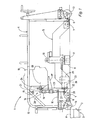
- An apparent in Fig. 1 grinding machine 1 is designed for grinding rails 2 of a track 3 and has an aggregate frame 4.
- a copy frame 5 is mounted, which is rotatably connected at its two longitudinal ends with the unit frame 4 about an axis extending in the longitudinal direction of the rail pivot axis 6.
- the copy frame 5 is provided with two spaced in the rail longitudinal direction sensing rollers 7, which are unrolled on a rail head 8 of the rail to be processed 2.
- a grinding member 9 is arranged on the copy frame 5, which is adjustable by means of a drive 10 relative to the rail 2 and has a rotatable grinding element 11.
- the unit frame 4 is connected to a vertical guide 14, which is formed of two spaced apart in the transverse direction of the track guide rods 15. These are fastened with their upper ends to the bracket 12, while they are mounted with their lower ends on a mounted on the unit frame 4 plate 16.
- a console-like support frame 17 is slidably supported by sliding sleeves 18 on the two guide rods 15 and serves to support a drive motor 19, which is thus mounted vertically adjustable on the unit frame 4.
- the - preferably designed as an internal combustion engine - drive motor 19 is connected to the grinding member 9 via a transmission 20 for transmitting power, having two vertically superposed pulleys 21,22 over which a drive belt 23 is guided.
- the upper pulley 21 is directly connected to a drive shaft 24 of the drive motor 19, while the lower pulley 22 is assigned to a arranged on the copy frame 5 and non-positively connected to the grinding member 9 bevel gear 25.
- the axes of rotation 26 of the two pulleys 21 and 22 are each aligned parallel to the pivot axis 6.
- the support frame 17 carrying the drive motor 19 is further connected to the copy frame 5 by means of a push rod 27, which is rotatably mounted both on the support frame 17 and on the copy frame 5 about a rotation axis 28 extending parallel to the pivot axis 6.
- the two axes of rotation 28 are aligned in each case to one of the two axes of rotation 26 of the pulleys 21 and 22 aligned.
- the push rod 27 is provided with a turnbuckle 29 and formed by means of the same length variable to the drive belt 23 by extending the push rod 27 re-tension or replace by shortening the push rod.
- FIG. 2 shows the grinding of a horizontal running surface 30 of the rail head 8.
- the axes 31 of rolling on the rail 2 sensing rollers 7 are horizontal, and the axis of rotation 26 of the lower pulley 22 is positioned in the vertical direction above the pivot axis 6 or centered.
- Fig. 3 the grinding of a side edge 32 of the rail head 8 can be seen.
- the copy frame 5 has been rotated for this purpose about the pivot axis 6, whereby the follower rollers 7 now roll on the side edge 32 of the rail head 8 of the rail 2 to be ground.
- the rotation of the copy frame 5 has the consequence that also hinged to this lower end 33 of the push rod 27 is mitverschwenkt and lowered accordingly.
- the push rod 27 acts as a driver and causes a corresponding lowering of the support frame 17 together with the drive motor 19 on the vertical guide 14. Due to the concentric alignment of the axes of rotation 28 of the push rod 27 with the axes of rotation 26 of the pulleys 21 and 22, the power transmission from the drive motor 19 the angular gear 25 is not affected by the pivoting in the slightest.
Landscapes
- Engineering & Computer Science (AREA)
- Mechanical Engineering (AREA)
- Architecture (AREA)
- Civil Engineering (AREA)
- Structural Engineering (AREA)
- Machines For Laying And Maintaining Railways (AREA)
- Finish Polishing, Edge Sharpening, And Grinding By Specific Grinding Devices (AREA)
- Grinding Of Cylindrical And Plane Surfaces (AREA)
- Disintegrating Or Milling (AREA)
- Mechanical Treatment Of Semiconductor (AREA)
- Constituent Portions Of Griding Lathes, Driving, Sensing And Control (AREA)
Description
- Die Erfindung betrifft eine Schleifmaschine zum Schleifen von Schienen eines Gleises, mit einem über Tastrollen auf einer Schiene abrollbaren, ein relativ zur Schiene verstellbares Schleiforgan aufweisenden Kopierrahmen, der um eine in Schienenlängsrichtung verlaufende Schwenkachse verschwenkbar an einem Aggregatrahmen mit auf den Schienen abrollbaren Führungsrollen gelagert ist, sowie mit einem am Aggregatrahmen montierten Antriebsmotor, der mit dem Schleiforgan über ein Getriebe zur Kraftübertragung verbunden ist.
- Eine derartige Schleifmaschine ist bereits aus der EP 0 743 395 B1 bekannt. Die Kraftübertragung vom Antriebsmotor auf das Schleiforgan erfolgt über ein Winkelgetriebe, das auf dem Kopierrahmen montiert und über eine flexible Welle mit dem Motor verbunden ist. Ein Keilriemenantrieb überträgt die Kraft vom Winkelgetriebe weiter auf das Schleiforgan. Im Zuge des Schleifens des Schienenkopfprofils muß der Kopierrahmen mitsamt dem Winkelgetriebe von der einen Schienenseitenflanke zur anderen über ca. 180° verschwenkt werden. Um diese Bewegung weitgehend ungehindert zu ermöglichen, ist die biegsame Welle zwecks Flexibilität mit relativ geringem Durchmesser ausgebildet, wobei die Welle aber während des Arbeitseinsatzes starker Beanspruchung ausgesetzt ist.
- In der EP 1 178 154 A1 ist eine weitere Schienenschleifmaschine geoffenbart, bei der der Antriebsmotor auf einem sowohl am Aggregatrahmen als auch - über ein Zwischenglied - am Kopierrahmen angelenkten bzw. um in Schienenlängsrichtung verlaufende Achsen verschwenkbaren Träger montiert ist. Das Zwischenglied ist gleichzeitig als Gehäuse für den Antriebsriemen ausgebildet. Bei der Rotation des Kopierrahmens um die Schwenkachse kommt es zu einer Höhenverstellung des mit diesem verbundenen Endes des wippenartig ausgeführten Trägers entlang einer Kreisbahn und damit zu einem seitlichen Kippen des Antriebsmotors aus der horizontalen Lage.
- Es ist weiters - beispielsweise aus DE 42 20 456 C1 - auch bekannt, den Antriebsmotor mitsamt dem Schleiforgan auf einem Zustellrahmen zu montieren, der auf dem Kopierrahmen über Führungsstangen senkrecht zur Schienenlängsrichtung verstellbar gelagert ist.
- Die Aufgabe der vorliegenden Erfindung liegt nun in der Schaffung einer Schleifmaschine der gattungsgemäßen Art, mit der eine einfache und zuverlässige Übertragung der Antriebskraft während aller Phasen des Arbeitseinsatzes möglich ist.
- Erfindungsgemäß wird diese Aufgabe mit einer Maschine der eingangs genannten Art dadurch gelöst, daß der Antriebsmotor auf einer mit dem Aggregatrahmen verbundenen Vertikalführung höhenverstellbar gelagert ist.
- Durch diese Ausbildung besteht nun die vorteilhafte Möglichkeit, den Antriebsmotor mit dem Kopierrahmen gelenkig zu koppeln, sodaß während der seitlichen Verschwenkung des Kopierrahmens um die Schwenkachse der Antriebsmotor eine - diese Bewegung kompensierende - Höhenverstellung mitmachen kann. Gleichzeitig ist dadurch in zuverlässiger Weise gewährleistet, daß der Antriebsmotor in allen Arbeitsphasen in unverändert vertikaler Position verbleibt, was besonders bei Verwendung von Verbrennungsmotoren von Bedeutung ist.
- Weitere Vorteile und Ausbildungen der Erfindung ergeben sich aus den Unteransprüchen und der Zeichnung.
- Im folgenden wird die Erfindung anhand von in der Zeichnung dargestellten Ausführungsbeispielen näher beschrieben.
- Es zeigen:
- Fig. 1 eine Seitenansicht einer erfindungsgemäß ausgebildeten Schienenschleifmaschine, und
- Fig. 2 und 3 je eine Schnittansicht in Schienenlängsrichtung von verschiedenen Arbeitspositionen der Maschine.
- Eine in Fig. 1 ersichtliche Schleifmaschine 1 ist zum Schleifen von Schienen 2 eines Gleises 3 ausgebildet und weist einen Aggregatrahmen 4 auf. An diesem ist ein Kopierrahmen 5 gelagert, der an seinen beiden Längsenden mit dem Aggregatrahmen 4 um eine in Schienenlängsrichtung verlaufende Schwenkachse 6 rotierbar verbunden ist. Weiters ist der Kopierrahmen 5 mit zwei in Schienenlängsrichtung voneinander distanzierten Tastrollen 7 ausgestattet, die auf einem Schienenkopf 8 der zu bearbeitenden Schiene 2 abrollbar sind. Mittig zwischen den beiden Tastrollen 7 ist ein Schleiforgan 9 am Kopierrahmen 5 angeordnet, das anhand eines Antriebes 10 relativ zur Schiene 2 verstellbar ausgebildet ist und ein rotierbares Schleifelement 11 aufweist.
- Der in Form eines vertikalen bzw. in Schienenlängsrichtung verlaufenden Bügels 12 ausgeführte Aggregatrahmen 4 ist an seinen beiden Längsenden mit Führungsrollen 13 versehen, die als Doppelspurkranzrollen ausgebildet und relativ zum Aggregatrahmen 4 gleitend querverstellbar sind. Bei seitlicher Verschwenkung um die Schwenkachse 6 bzw. daraus folgender Absenkung des Kopierrahmens 5 rollen die Führungsrollen 13 auf dem Schienenkopf 8 ab und führen so den Aggregatrahmen 4 auf der zu schleifenden Schiene 2, wobei der Aggragatrahmen 4 mittels eines (nicht näher dargestellten) Auslegers auch auf der anderen Schiene 2 des Gleises 3 abgestützt ist. (Für genauere Erläuterungen dieser bereits bekannten Ausbildung wird auf die EP 0 743 395 B1 verwiesen).
- Wie im weiteren nun auch anhand der Figuren 2 und 3 ersichtlich, ist der Aggregatrahmen 4 mit einer Vertikalführung 14 verbunden, die aus zwei in Gleisquerrichtung voneinander distanzierten Führungsstangen 15 gebildet ist. Diese sind mit ihren oberen Enden am Bügel 12 befestigt, während sie mit ihren unteren Enden auf einer am Aggregatrahmen 4 gelagerten Platte 16 montiert sind. Ein konsolenartiger Stützrahmen 17 ist anhand von Gleitmanschetten 18 auf den beiden Führungsstangen 15 gleitend gelagert und dient zur Abstützung eines Antriebsmotors 19, der somit höhenverstellbar am Aggregatrahmen 4 gelagert ist.
- Der - vorzugsweise als Verbrennungsmotor ausgebildete - Antriebsmotor 19 ist mit dem Schleiforgan 9 über ein Getriebe 20 zur Kraftübertragung verbunden, das zwei in vertikaler Richtung übereinander positionierte Riemenscheiben 21,22 aufweist, über die ein Antriebsriemen 23 geführt ist. Dabei ist die obere Riemenscheibe 21 direkt mit einer Antriebswelle 24 des Antriebsmotors 19 verbunden, während die untere Riemenscheibe 22 einem auf dem Kopierrahmen 5 angeordneten und mit dem Schleiforgan 9 kraftschlüssig verbundenen Winkelgetriebe 25 zugeordnet ist. Die Rotationsachsen 26 der beiden Riemenscheiben 21 und 22 sind jeweils parallel zur Schwenkachse 6 ausgerichtet.
- Der den Antriebsmotor 19 tragende Stützrahmen 17 ist weiters mit dem Kopierrahmen 5 anhand einer Schubstange 27 verbunden, die sowohl am Stützrahmen 17 als auch am Kopierrahmen 5 jeweils um eine parallel zur Schwenkachse 6 verlaufende Drehachse 28 rotierbar gelagert ist. Die beiden Drehachsen 28 sind dabei jeweils zu einer der beiden Rotationsachsen 26 der Riemenscheiben 21 bzw. 22 fluchtend ausgerichtet. Die Schubstange 27 ist mit einem Spannschloß 29 versehen und anhand desselben längenveränderbar ausgebildet, um den Antriebsriemen 23 durch Verlängern der Schubstange 27 nachspannen bzw. durch Verkürzen der Schubstange auswechseln zu können.
- Die in Fig. 2 dargestellte Situation zeigt das Schleifen einer horizontalen Fahrfläche 30 des Schienenkopfes 8. Dabei stehen die Achsen 31 der auf der Schiene 2 abrollenden Tastrollen 7 horizontal, und die Rotationsachse 26 der unteren Riemenscheibe 22 ist in vertikaler Richtung über der Schwenkachse 6 positioniert bzw. zentriert.
- In Fig. 3 ist das Schleifen einer Seitenflanke 32 des Schienenkopfes 8 zu sehen. Der Kopierrahmen 5 ist zu diesem Zweck um die Schwenkachse 6 gedreht worden, wodurch die Tastrollen 7 nun auf der Seitenflanke 32 des Schienenkopfes 8 der zu schleifenden Schiene 2 abrollen. Die Verdrehung des Kopierrahmens 5 hat zur Folge, daß auch das an diesem angelenkte untere Ende 33 der Schubstange 27 mitverschwenkt und dementsprechend abgesenkt wird. Dabei fungiert die Schubstange 27 als Mitnehmer und bewirkt eine entsprechende Absenkung des Stützrahmens 17 mitsamt dem Antriebsmotor 19 auf der Vertikalführung 14. Aufgrund der konzentrischen Ausrichtung der Drehachsen 28 der Schubstange 27 mit den Rotationsachsen 26 der Riemenscheiben 21 und 22 wird die Kraftübertragung vom Antriebsmotor 19 auf das Winkelgetriebe 25 durch die Verschwenkung nicht im Geringsten beeinträchtigt.
Claims (7)
- Schleifmaschine zum Schleifen von Schienen eines Gleises, mit einem über Tastrollen (7) auf einer Schiene (2) abrollbaren, ein relativ zur Schiene (2) verstellbares Schleiforgan (9) aufweisenden Kopierrahmen (5), der um eine in Schienenlängsrichtung verlaufende Schwenkachse (6) verschwenkbar an einem Aggregatrahmen (4) mit auf den Schienen (2) abrollbaren Führungsrollen (13) gelagert ist, sowie mit einem am Aggregatrahmen (4) montierten Antriebsmotor (19), der mit dem Schleiforgan (9) über ein Getriebe (20) zur Kraftübertragung verbunden ist, dadurch gekennzeichnet, daß der Antriebsmotor (19) auf einer mit dem Aggregatrahmen (4) verbundenen Vertikalführung (14) höhenverstellbar gelagert ist.
- Schleifmaschine nach Anspruch 1, dadurch gekennzeichnet, daß der Antriebsmotor (19) mit dem Kopierrahmen (5) über eine Schubstange (27) verbunden ist, die am Kopierrahmen (5) um eine parallel zur Schwenkachse (6) verlaufende Drehachse (28) rotierbar gelagert ist.
- Schleifmaschine nach Anspruch 2, dadurch gekennzeichnet, daß der Antriebsmotor (19) auf einem konsolenartigen Stützrahmen (17) befestigt ist, der seinerseits auf der Vertikalführung (14) gleitend gelagert ist und mit dem die Schubstange (27) um eine parallel zur Schwenkachse (6) verlaufende Drehachse (28) rotierbar verbunden ist.
- Schleifmaschine nach einem der Ansprüche 2 bis 3 , dadurch gekennzeichnet, daß das Getriebe (20) aus einem über zwei in vertikaler Richtung übereinander positionierten Riemenscheiben (21,22) mit Rotationsachsen (26) geführten Antriebsriemen (23) gebildet ist, wobei die Rotationsachsen (26) jeweils zu einer der Drehachsen (28) der Schubstange (27) fluchtend ausgerichtet sind.
- Schleifmaschine nach Anspruch 3 oder 4, dadurch gekennzeichnet, daß die Schubstange (27) längenveränderbar ausgebildet ist.
- Schleifmaschine nach Anspruch 5, dadurch gekennzeichnet, daß die Schubstange (27) mit einem Spannschloß (29) zur Längenveränderung versehen ist.
- Schleifmaschine nach einem der Ansprüche 1 bis 6, dadurch gekennzeichnet, daß die Vertikalführung (14) aus zwei in Gleisquerrichtung voneinander distanzierten Führungsstangen (15) gebildet ist.
Applications Claiming Priority (2)
| Application Number | Priority Date | Filing Date | Title |
|---|---|---|---|
| DE20210021U DE20210021U1 (de) | 2002-06-28 | 2002-06-28 | Schleifmaschine |
| DE20210021U | 2002-06-28 |
Publications (3)
| Publication Number | Publication Date |
|---|---|
| EP1375749A2 EP1375749A2 (de) | 2004-01-02 |
| EP1375749A3 EP1375749A3 (de) | 2004-08-11 |
| EP1375749B1 true EP1375749B1 (de) | 2006-10-04 |
Family
ID=7972642
Family Applications (1)
| Application Number | Title | Priority Date | Filing Date |
|---|---|---|---|
| EP03450127A Expired - Lifetime EP1375749B1 (de) | 2002-06-28 | 2003-05-21 | Schleifmaschine |
Country Status (10)
| Country | Link |
|---|---|
| US (1) | US6805621B2 (de) |
| EP (1) | EP1375749B1 (de) |
| CN (1) | CN1276152C (de) |
| AT (1) | ATE341663T1 (de) |
| AU (1) | AU2003205024B2 (de) |
| CA (1) | CA2433986C (de) |
| DE (2) | DE20210021U1 (de) |
| PL (1) | PL203386B1 (de) |
| RU (1) | RU2245955C1 (de) |
| UA (1) | UA80672C2 (de) |
Cited By (1)
| Publication number | Priority date | Publication date | Assignee | Title |
|---|---|---|---|---|
| WO2026114464A1 (de) * | 2024-11-29 | 2026-06-04 | Maik Bartel | Haltevorrichtung für winkelschleifer |
Families Citing this family (30)
| Publication number | Priority date | Publication date | Assignee | Title |
|---|---|---|---|---|
| CH698609B1 (fr) * | 2005-09-16 | 2009-09-15 | Speno Internat S A | Dispositif de reprofilage des rails de chemins de fer avec captage des déchets. |
| DE102005044786A1 (de) * | 2005-09-20 | 2007-03-29 | Robel Bahnbaumaschinen Gmbh | Vorrichtung zum Reprofilieren einer Schiene eines Gleises und Verfahren |
| DE202006004970U1 (de) * | 2006-03-29 | 2006-06-08 | Robel Bahnbaumaschinen Gmbh | Vorrichtung zum Schleifen von Schienen eines Gleises |
| DE202010007264U1 (de) * | 2010-05-26 | 2010-08-26 | Robel Bahnbaumaschinen Gmbh | Schleifmaschine zum Schleifen von Schienen eines Gleises |
| CN103132410B (zh) * | 2011-12-03 | 2014-12-10 | 金鹰重型工程机械有限公司 | 一种钢轨高速打磨列车的打磨装置 |
| CN102561119B (zh) * | 2012-01-20 | 2014-01-22 | 沈阳铁路局科学技术研究所 | 小型钢轨轨底焊缝自动打磨机 |
| EP2620546A1 (de) | 2012-01-26 | 2013-07-31 | Tirso a.s. | Robotervorrichtung zum Anschweißen von Krangleisen |
| CN102848316B (zh) * | 2012-08-16 | 2014-07-09 | 湖南海捷精密工业有限公司 | 钢轨铣磨车纵向进给自适应装置 |
| CN103510438B (zh) * | 2013-07-29 | 2015-08-19 | 株洲时代电子技术有限公司 | 一种钢轨打磨车优化打磨装置 |
| RU2539309C1 (ru) * | 2013-09-19 | 2015-01-20 | Открытое акционерное общество Научно-исследовательский и конструкторско-технологический институт подвижного состава (ОАО "ВНИКТИ") | Устройство для шлифовки головки рельса |
| CN103753372B (zh) * | 2014-01-09 | 2016-06-22 | 张文学 | 数控道岔打磨机 |
| CN103924490A (zh) * | 2014-04-22 | 2014-07-16 | 北京二七机车工业有限责任公司 | 钢轨打磨车打磨单元倾斜装置 |
| CN104195905B (zh) * | 2014-08-08 | 2016-06-29 | 张晶晶 | 电动仿形钢轨打磨机 |
| FR3025228B1 (fr) * | 2014-09-03 | 2016-12-23 | Robert Pouget | Machine autonome de meulage des rails presentant des defauts d'usure ondulatoire verticale et laterale |
| CN104454740B (zh) * | 2014-12-31 | 2017-02-01 | 中车北京二七机车有限公司 | 铣削装置液压系统及钢轨铣磨车 |
| CN104625930B (zh) * | 2015-03-11 | 2017-01-25 | 戚恒 | 一种钢轨打磨机 |
| CN105773696A (zh) * | 2016-04-14 | 2016-07-20 | 南通德瑞森复合材料有限公司 | 一种玻璃钢构件表面打划痕器 |
| CN106120635B (zh) * | 2016-06-28 | 2017-11-21 | 江苏创迈达智能科技有限公司 | 一种铁路轨道智能清洗机器人 |
| CN106120492B (zh) * | 2016-06-28 | 2017-11-10 | 胡妹芳 | 一种基于并联机构的轨道智能清洗机械爪 |
| CN106120494B (zh) * | 2016-06-28 | 2017-10-17 | 中铁六局集团有限公司 | 一种动车轨道智能打磨一体机 |
| CN106120493B (zh) * | 2016-06-28 | 2017-11-17 | 赵冬领 | 一种火车轨道智能打磨机 |
| DE202017000696U1 (de) | 2017-02-09 | 2017-03-16 | Robel Bahnbaumaschinen Gmbh | Schleifmaschine zum Schleifen von Schienen eines Gleises |
| CN107139046B (zh) * | 2017-05-16 | 2018-12-14 | 来安县华鹏摩擦材料厂 | 一种刹车离合片用打磨装置 |
| CN107130482B (zh) * | 2017-06-05 | 2019-10-25 | 武汉理工大学 | 一种可变幅式铁轨打磨机 |
| CN107938444B (zh) * | 2017-11-15 | 2019-03-15 | 安徽工程大学 | 一种可减震的磨轨机 |
| FR3077077B1 (fr) * | 2018-01-24 | 2019-12-20 | Societe Turripinoise De Mecanique | Meuleuse de rails |
| CN110952404A (zh) * | 2019-12-31 | 2020-04-03 | 北京交通大学 | 偏转上驱型砂带式钢轨打磨装置 |
| CN117822360B (zh) * | 2023-12-28 | 2024-07-26 | 高速铁路建造技术国家工程研究中心 | 一种高铁装配式轨道结构底座板用位形调整设备 |
| US20250290254A1 (en) * | 2024-03-15 | 2025-09-18 | Sperling Railway Services, Inc. | Rail grinding machine and method thereof |
| CN121295569B (zh) * | 2025-12-15 | 2026-04-14 | 北京交大麒麟慧通科技有限公司 | 一种轨面打磨设备 |
Family Cites Families (10)
| Publication number | Priority date | Publication date | Assignee | Title |
|---|---|---|---|---|
| US388052A (en) * | 1888-08-21 | Multiple switch-board | ||
| US2073816A (en) * | 1935-11-16 | 1937-03-16 | Nordberg Manufacturing Co | Track grinder |
| CH548488A (fr) * | 1972-06-08 | 1974-04-30 | Speno International | Procede de rectification en voie d'une file de rails par meulage de sa surface de roulement et dispositif pour la mise en oeuvre de ce procede. |
| US3883323A (en) * | 1974-09-06 | 1975-05-13 | Lush E Cooley | Welded railroad rail grinding apparatus |
| AT344772B (de) * | 1975-12-01 | 1978-08-10 | Plasser Bahnbaumasch Franz | Schienenschleifmaschine |
| CH620008A5 (de) * | 1978-03-03 | 1980-10-31 | Efsa | |
| AT388764B (de) * | 1987-05-12 | 1989-08-25 | Plasser Bahnbaumasch Franz | Band-schleifaggregat zum abschleifen von unregelmaessigkeiten an der schienenkopfflaeche einer oder beider schienen eines verlegten gleises |
| DE4220456C1 (de) * | 1992-06-23 | 1993-10-28 | Elektro Thermit Gmbh | Schienenschleifmaschine |
| DE19518457A1 (de) * | 1995-05-19 | 1996-11-21 | Robel Georg Gmbh & Co | Vorrichtung zum Schleifen von Schienen |
| FR2812670B1 (fr) | 2000-08-01 | 2002-10-04 | Turripinoise De Mecanique S A | Meuleuse de profils de rails |
-
2002
- 2002-06-28 DE DE20210021U patent/DE20210021U1/de not_active Expired - Lifetime
-
2003
- 2003-05-21 AT AT03450127T patent/ATE341663T1/de active
- 2003-05-21 DE DE50305230T patent/DE50305230D1/de not_active Expired - Lifetime
- 2003-05-21 EP EP03450127A patent/EP1375749B1/de not_active Expired - Lifetime
- 2003-06-12 PL PL360648A patent/PL203386B1/pl unknown
- 2003-06-13 US US10/462,309 patent/US6805621B2/en not_active Expired - Fee Related
- 2003-06-26 RU RU2003118940/11A patent/RU2245955C1/ru not_active IP Right Cessation
- 2003-06-27 UA UA2003066033A patent/UA80672C2/uk unknown
- 2003-06-27 CA CA002433986A patent/CA2433986C/en not_active Expired - Fee Related
- 2003-06-27 CN CN03148403.4A patent/CN1276152C/zh not_active Expired - Fee Related
- 2003-06-27 AU AU2003205024A patent/AU2003205024B2/en not_active Ceased
Cited By (1)
| Publication number | Priority date | Publication date | Assignee | Title |
|---|---|---|---|---|
| WO2026114464A1 (de) * | 2024-11-29 | 2026-06-04 | Maik Bartel | Haltevorrichtung für winkelschleifer |
Also Published As
| Publication number | Publication date |
|---|---|
| CA2433986C (en) | 2006-11-21 |
| CN1276152C (zh) | 2006-09-20 |
| UA80672C2 (en) | 2007-10-25 |
| US6805621B2 (en) | 2004-10-19 |
| CA2433986A1 (en) | 2003-12-28 |
| DE50305230D1 (de) | 2006-11-16 |
| EP1375749A3 (de) | 2004-08-11 |
| AU2003205024B2 (en) | 2008-05-29 |
| PL360648A1 (en) | 2003-12-29 |
| EP1375749A2 (de) | 2004-01-02 |
| US20040002294A1 (en) | 2004-01-01 |
| PL203386B1 (pl) | 2009-09-30 |
| CN1469010A (zh) | 2004-01-21 |
| DE20210021U1 (de) | 2002-11-14 |
| AU2003205024A1 (en) | 2004-01-22 |
| ATE341663T1 (de) | 2006-10-15 |
| RU2245955C1 (ru) | 2005-02-10 |
Similar Documents
| Publication | Publication Date | Title |
|---|---|---|
| EP1375749A2 (de) | Schleifmaschine | |
| EP0743395B1 (de) | Vorrichtung zum Schleifen von Schienen | |
| EP2576909B1 (de) | Schleifmaschine zum schleifen von schienen eines gleises | |
| EP0340234B1 (de) | Schlauchband-förderanlage | |
| EP0897826B1 (de) | Maschine zum Verlegen eines Fahrdrahtes | |
| DE2926045C2 (de) | Gleisbaumaschine zum Verteilen und Profilieren des Bettungsschotters eines Gleises | |
| DE3423239A1 (de) | Naehmaschine | |
| DE3221011A1 (de) | Walze | |
| EP1949982B1 (de) | Walzvorrichtung und Verfahren zum Einrollen von Verbindungsstegen in Profile | |
| DE3138820A1 (de) | Vorrichtung zum einschieben von stahlstaeben oder dergleichen in ein huellrohr zur bildung eines buendelzugglieds | |
| EP0146006B1 (de) | Röntgendiagnostikgerät mit einem Kipptisch | |
| DE1966630A1 (de) | Hubvorrichtung fuer kraftfahrzeuge | |
| DE3828094C2 (de) | ||
| DE3741537A1 (de) | Schlauchband-foerderanlage | |
| DE3405921A1 (de) | Bedienungsplatz fuer traktoren und arbeitsmaschinen | |
| DE3721969C2 (de) | Vorrichtung zum Aufwickeln einer Folienbahn, insbes. einer Kunststoffolienbahn, zu einem Folienwickel auf einem Wickelkern | |
| EP1072435A1 (de) | Einrichtung für das Beleimen der Aussenflächen von in einer Buchblockeinhängemaschine in Buchdecken einzuhängende Buchblocks | |
| DE202006004970U1 (de) | Vorrichtung zum Schleifen von Schienen eines Gleises | |
| DE2632132C2 (de) | Vorrichtung zum Schraubenschneiden einer Schlauchware | |
| DE3123502A1 (de) | Maschine zum feinbearbeiten der zahnflanken von verzahnten werkstuecken | |
| DE2901497A1 (de) | Aufwickelvorrichtung zum direkten ziehen von glasfaser aus einer duesenplatte zur herstellung einer praezisionswicklung | |
| WO2003070532A1 (de) | Kraftfahrzeug-waschstrasse mit einer ausbalancierten dachrolle | |
| DE928137C (de) | Einrichtung an nach einer Zeichnung arbeitenden Kopierbrennschneidmaschinen | |
| DE968324C (de) | Roentgengeraet mit an einer umlegbaren Patientenlagerstatt unter Gewichtsausgleich verstellbar angeordneten Geraeteteilen | |
| DE3507084A1 (de) | Vorrichtung zum fuehren und ausbreiten einer warenbahn |
Legal Events
| Date | Code | Title | Description |
|---|---|---|---|
| PUAI | Public reference made under article 153(3) epc to a published international application that has entered the european phase |
Free format text: ORIGINAL CODE: 0009012 |
|
| AK | Designated contracting states |
Kind code of ref document: A2 Designated state(s): AT BE BG CH CY CZ DE DK EE ES FI FR GB GR HU IE IT LI LU MC NL PT RO SE SI SK TR |
|
| AX | Request for extension of the european patent |
Extension state: AL LT LV MK |
|
| PUAL | Search report despatched |
Free format text: ORIGINAL CODE: 0009013 |
|
| AK | Designated contracting states |
Kind code of ref document: A3 Designated state(s): AT BE BG CH CY CZ DE DK EE ES FI FR GB GR HU IE IT LI LU MC NL PT RO SE SI SK TR |
|
| AX | Request for extension of the european patent |
Extension state: AL LT LV MK |
|
| 17P | Request for examination filed |
Effective date: 20050211 |
|
| AKX | Designation fees paid |
Designated state(s): AT BE BG CH CY CZ DE DK EE ES FI FR GB GR HU IE IT LI LU MC NL PT RO SE SI SK TR |
|
| GRAP | Despatch of communication of intention to grant a patent |
Free format text: ORIGINAL CODE: EPIDOSNIGR1 |
|
| GRAS | Grant fee paid |
Free format text: ORIGINAL CODE: EPIDOSNIGR3 |
|
| GRAA | (expected) grant |
Free format text: ORIGINAL CODE: 0009210 |
|
| AK | Designated contracting states |
Kind code of ref document: B1 Designated state(s): AT BE BG CH CY CZ DE DK EE ES FI FR GB GR HU IE IT LI LU MC NL PT RO SE SI SK TR |
|
| PG25 | Lapsed in a contracting state [announced via postgrant information from national office to epo] |
Ref country code: FI Free format text: LAPSE BECAUSE OF FAILURE TO SUBMIT A TRANSLATION OF THE DESCRIPTION OR TO PAY THE FEE WITHIN THE PRESCRIBED TIME-LIMIT Effective date: 20061004 Ref country code: SI Free format text: LAPSE BECAUSE OF FAILURE TO SUBMIT A TRANSLATION OF THE DESCRIPTION OR TO PAY THE FEE WITHIN THE PRESCRIBED TIME-LIMIT Effective date: 20061004 Ref country code: IT Free format text: LAPSE BECAUSE OF FAILURE TO SUBMIT A TRANSLATION OF THE DESCRIPTION OR TO PAY THE FEE WITHIN THE PRESCRIBED TIME-LIMIT;WARNING: LAPSES OF ITALIAN PATENTS WITH EFFECTIVE DATE BEFORE 2007 MAY HAVE OCCURRED AT ANY TIME BEFORE 2007. THE CORRECT EFFECTIVE DATE MAY BE DIFFERENT FROM THE ONE RECORDED. Effective date: 20061004 Ref country code: SK Free format text: LAPSE BECAUSE OF FAILURE TO SUBMIT A TRANSLATION OF THE DESCRIPTION OR TO PAY THE FEE WITHIN THE PRESCRIBED TIME-LIMIT Effective date: 20061004 Ref country code: IE Free format text: LAPSE BECAUSE OF FAILURE TO SUBMIT A TRANSLATION OF THE DESCRIPTION OR TO PAY THE FEE WITHIN THE PRESCRIBED TIME-LIMIT Effective date: 20061004 Ref country code: NL Free format text: LAPSE BECAUSE OF FAILURE TO SUBMIT A TRANSLATION OF THE DESCRIPTION OR TO PAY THE FEE WITHIN THE PRESCRIBED TIME-LIMIT Effective date: 20061004 |
|
| REG | Reference to a national code |
Ref country code: GB Ref legal event code: FG4D Free format text: NOT ENGLISH |
|
| REG | Reference to a national code |
Ref country code: CH Ref legal event code: EP |
|
| REG | Reference to a national code |
Ref country code: IE Ref legal event code: FG4D Free format text: LANGUAGE OF EP DOCUMENT: GERMAN |
|
| REF | Corresponds to: |
Ref document number: 50305230 Country of ref document: DE Date of ref document: 20061116 Kind code of ref document: P |
|
| REG | Reference to a national code |
Ref country code: RO Ref legal event code: EPE |
|
| PG25 | Lapsed in a contracting state [announced via postgrant information from national office to epo] |
Ref country code: DK Free format text: LAPSE BECAUSE OF FAILURE TO SUBMIT A TRANSLATION OF THE DESCRIPTION OR TO PAY THE FEE WITHIN THE PRESCRIBED TIME-LIMIT Effective date: 20070104 Ref country code: BG Free format text: LAPSE BECAUSE OF FAILURE TO SUBMIT A TRANSLATION OF THE DESCRIPTION OR TO PAY THE FEE WITHIN THE PRESCRIBED TIME-LIMIT Effective date: 20070104 |
|
| REG | Reference to a national code |
Ref country code: SE Ref legal event code: TRGR |
|
| PG25 | Lapsed in a contracting state [announced via postgrant information from national office to epo] |
Ref country code: ES Free format text: LAPSE BECAUSE OF FAILURE TO SUBMIT A TRANSLATION OF THE DESCRIPTION OR TO PAY THE FEE WITHIN THE PRESCRIBED TIME-LIMIT Effective date: 20070115 |
|
| GBT | Gb: translation of ep patent filed (gb section 77(6)(a)/1977) |
Effective date: 20070103 |
|
| REG | Reference to a national code |
Ref country code: HU Ref legal event code: AG4A Ref document number: E001013 Country of ref document: HU |
|
| PG25 | Lapsed in a contracting state [announced via postgrant information from national office to epo] |
Ref country code: PT Free format text: LAPSE BECAUSE OF FAILURE TO SUBMIT A TRANSLATION OF THE DESCRIPTION OR TO PAY THE FEE WITHIN THE PRESCRIBED TIME-LIMIT Effective date: 20070316 |
|
| ET | Fr: translation filed | ||
| NLV1 | Nl: lapsed or annulled due to failure to fulfill the requirements of art. 29p and 29m of the patents act | ||
| REG | Reference to a national code |
Ref country code: IE Ref legal event code: FD4D |
|
| PLBE | No opposition filed within time limit |
Free format text: ORIGINAL CODE: 0009261 |
|
| STAA | Information on the status of an ep patent application or granted ep patent |
Free format text: STATUS: NO OPPOSITION FILED WITHIN TIME LIMIT |
|
| 26N | No opposition filed |
Effective date: 20070705 |
|
| PG25 | Lapsed in a contracting state [announced via postgrant information from national office to epo] |
Ref country code: MC Free format text: LAPSE BECAUSE OF NON-PAYMENT OF DUE FEES Effective date: 20070531 |
|
| PG25 | Lapsed in a contracting state [announced via postgrant information from national office to epo] |
Ref country code: GR Free format text: LAPSE BECAUSE OF FAILURE TO SUBMIT A TRANSLATION OF THE DESCRIPTION OR TO PAY THE FEE WITHIN THE PRESCRIBED TIME-LIMIT Effective date: 20070105 |
|
| PG25 | Lapsed in a contracting state [announced via postgrant information from national office to epo] |
Ref country code: EE Free format text: LAPSE BECAUSE OF FAILURE TO SUBMIT A TRANSLATION OF THE DESCRIPTION OR TO PAY THE FEE WITHIN THE PRESCRIBED TIME-LIMIT Effective date: 20061004 |
|
| PG25 | Lapsed in a contracting state [announced via postgrant information from national office to epo] |
Ref country code: LU Free format text: LAPSE BECAUSE OF NON-PAYMENT OF DUE FEES Effective date: 20070521 Ref country code: CY Free format text: LAPSE BECAUSE OF FAILURE TO SUBMIT A TRANSLATION OF THE DESCRIPTION OR TO PAY THE FEE WITHIN THE PRESCRIBED TIME-LIMIT Effective date: 20061004 |
|
| PG25 | Lapsed in a contracting state [announced via postgrant information from national office to epo] |
Ref country code: TR Free format text: LAPSE BECAUSE OF FAILURE TO SUBMIT A TRANSLATION OF THE DESCRIPTION OR TO PAY THE FEE WITHIN THE PRESCRIBED TIME-LIMIT Effective date: 20061004 |
|
| PGFP | Annual fee paid to national office [announced via postgrant information from national office to epo] |
Ref country code: HU Payment date: 20130514 Year of fee payment: 11 Ref country code: IT Payment date: 20130525 Year of fee payment: 11 Ref country code: RO Payment date: 20130514 Year of fee payment: 11 |
|
| PG25 | Lapsed in a contracting state [announced via postgrant information from national office to epo] |
Ref country code: RO Free format text: LAPSE BECAUSE OF NON-PAYMENT OF DUE FEES Effective date: 20140521 |
|
| PG25 | Lapsed in a contracting state [announced via postgrant information from national office to epo] |
Ref country code: HU Free format text: LAPSE BECAUSE OF NON-PAYMENT OF DUE FEES Effective date: 20140522 |
|
| PG25 | Lapsed in a contracting state [announced via postgrant information from national office to epo] |
Ref country code: IT Free format text: LAPSE BECAUSE OF NON-PAYMENT OF DUE FEES Effective date: 20140521 |
|
| REG | Reference to a national code |
Ref country code: FR Ref legal event code: PLFP Year of fee payment: 14 |
|
| REG | Reference to a national code |
Ref country code: FR Ref legal event code: PLFP Year of fee payment: 15 |
|
| REG | Reference to a national code |
Ref country code: FR Ref legal event code: PLFP Year of fee payment: 16 |
|
| PGFP | Annual fee paid to national office [announced via postgrant information from national office to epo] |
Ref country code: FR Payment date: 20200519 Year of fee payment: 18 Ref country code: CH Payment date: 20200522 Year of fee payment: 18 Ref country code: CZ Payment date: 20200511 Year of fee payment: 18 Ref country code: DE Payment date: 20200504 Year of fee payment: 18 |
|
| PGFP | Annual fee paid to national office [announced via postgrant information from national office to epo] |
Ref country code: SE Payment date: 20200525 Year of fee payment: 18 Ref country code: BE Payment date: 20200518 Year of fee payment: 18 Ref country code: GB Payment date: 20200522 Year of fee payment: 18 |
|
| PGFP | Annual fee paid to national office [announced via postgrant information from national office to epo] |
Ref country code: AT Payment date: 20200513 Year of fee payment: 18 |
|
| REG | Reference to a national code |
Ref country code: DE Ref legal event code: R119 Ref document number: 50305230 Country of ref document: DE |
|
| REG | Reference to a national code |
Ref country code: SE Ref legal event code: EUG |
|
| REG | Reference to a national code |
Ref country code: CH Ref legal event code: PL |
|
| REG | Reference to a national code |
Ref country code: AT Ref legal event code: MM01 Ref document number: 341663 Country of ref document: AT Kind code of ref document: T Effective date: 20210521 |
|
| GBPC | Gb: european patent ceased through non-payment of renewal fee |
Effective date: 20210521 |
|
| PG25 | Lapsed in a contracting state [announced via postgrant information from national office to epo] |
Ref country code: LI Free format text: LAPSE BECAUSE OF NON-PAYMENT OF DUE FEES Effective date: 20210531 Ref country code: AT Free format text: LAPSE BECAUSE OF NON-PAYMENT OF DUE FEES Effective date: 20210521 Ref country code: CH Free format text: LAPSE BECAUSE OF NON-PAYMENT OF DUE FEES Effective date: 20210531 Ref country code: SE Free format text: LAPSE BECAUSE OF NON-PAYMENT OF DUE FEES Effective date: 20210522 Ref country code: CZ Free format text: LAPSE BECAUSE OF NON-PAYMENT OF DUE FEES Effective date: 20210521 |
|
| REG | Reference to a national code |
Ref country code: BE Ref legal event code: MM Effective date: 20210531 |
|
| PG25 | Lapsed in a contracting state [announced via postgrant information from national office to epo] |
Ref country code: GB Free format text: LAPSE BECAUSE OF NON-PAYMENT OF DUE FEES Effective date: 20210521 Ref country code: DE Free format text: LAPSE BECAUSE OF NON-PAYMENT OF DUE FEES Effective date: 20211201 |
|
| PG25 | Lapsed in a contracting state [announced via postgrant information from national office to epo] |
Ref country code: FR Free format text: LAPSE BECAUSE OF NON-PAYMENT OF DUE FEES Effective date: 20210531 |
|
| PG25 | Lapsed in a contracting state [announced via postgrant information from national office to epo] |
Ref country code: BE Free format text: LAPSE BECAUSE OF NON-PAYMENT OF DUE FEES Effective date: 20210531 |