EP1370436B1 - Ensemble joint - Google Patents
Ensemble joint Download PDFInfo
- Publication number
- EP1370436B1 EP1370436B1 EP02740420A EP02740420A EP1370436B1 EP 1370436 B1 EP1370436 B1 EP 1370436B1 EP 02740420 A EP02740420 A EP 02740420A EP 02740420 A EP02740420 A EP 02740420A EP 1370436 B1 EP1370436 B1 EP 1370436B1
- Authority
- EP
- European Patent Office
- Prior art keywords
- latching
- region
- sealing
- profile
- sealing arrangement
- Prior art date
- Legal status (The legal status is an assumption and is not a legal conclusion. Google has not performed a legal analysis and makes no representation as to the accuracy of the status listed.)
- Expired - Lifetime
Links
Images
Classifications
-
- F—MECHANICAL ENGINEERING; LIGHTING; HEATING; WEAPONS; BLASTING
- F16—ENGINEERING ELEMENTS AND UNITS; GENERAL MEASURES FOR PRODUCING AND MAINTAINING EFFECTIVE FUNCTIONING OF MACHINES OR INSTALLATIONS; THERMAL INSULATION IN GENERAL
- F16J—PISTONS; CYLINDERS; SEALINGS
- F16J15/00—Sealings
- F16J15/02—Sealings between relatively-stationary surfaces
- F16J15/021—Sealings between relatively-stationary surfaces with elastic packing
- F16J15/022—Sealings between relatively-stationary surfaces with elastic packing characterised by structure or material
- F16J15/024—Sealings between relatively-stationary surfaces with elastic packing characterised by structure or material the packing being locally weakened in order to increase elasticity
- F16J15/027—Sealings between relatively-stationary surfaces with elastic packing characterised by structure or material the packing being locally weakened in order to increase elasticity and with a hollow profile
-
- B—PERFORMING OPERATIONS; TRANSPORTING
- B60—VEHICLES IN GENERAL
- B60J—WINDOWS, WINDSCREENS, NON-FIXED ROOFS, DOORS, OR SIMILAR DEVICES FOR VEHICLES; REMOVABLE EXTERNAL PROTECTIVE COVERINGS SPECIALLY ADAPTED FOR VEHICLES
- B60J10/00—Sealing arrangements
- B60J10/15—Sealing arrangements characterised by the material
- B60J10/16—Sealing arrangements characterised by the material consisting of two or more plastic materials having different physical or chemical properties
-
- B—PERFORMING OPERATIONS; TRANSPORTING
- B60—VEHICLES IN GENERAL
- B60J—WINDOWS, WINDSCREENS, NON-FIXED ROOFS, DOORS, OR SIMILAR DEVICES FOR VEHICLES; REMOVABLE EXTERNAL PROTECTIVE COVERINGS SPECIALLY ADAPTED FOR VEHICLES
- B60J10/00—Sealing arrangements
- B60J10/20—Sealing arrangements characterised by the shape
- B60J10/23—Sealing arrangements characterised by the shape assembled from two or more parts
- B60J10/235—Sealing arrangements characterised by the shape assembled from two or more parts the parts being joined along their longitudinal direction
-
- B—PERFORMING OPERATIONS; TRANSPORTING
- B60—VEHICLES IN GENERAL
- B60J—WINDOWS, WINDSCREENS, NON-FIXED ROOFS, DOORS, OR SIMILAR DEVICES FOR VEHICLES; REMOVABLE EXTERNAL PROTECTIVE COVERINGS SPECIALLY ADAPTED FOR VEHICLES
- B60J10/00—Sealing arrangements
- B60J10/20—Sealing arrangements characterised by the shape
- B60J10/24—Sealing arrangements characterised by the shape having tubular parts
-
- B—PERFORMING OPERATIONS; TRANSPORTING
- B60—VEHICLES IN GENERAL
- B60J—WINDOWS, WINDSCREENS, NON-FIXED ROOFS, DOORS, OR SIMILAR DEVICES FOR VEHICLES; REMOVABLE EXTERNAL PROTECTIVE COVERINGS SPECIALLY ADAPTED FOR VEHICLES
- B60J10/00—Sealing arrangements
- B60J10/30—Sealing arrangements characterised by the fastening means
-
- B—PERFORMING OPERATIONS; TRANSPORTING
- B60—VEHICLES IN GENERAL
- B60J—WINDOWS, WINDSCREENS, NON-FIXED ROOFS, DOORS, OR SIMILAR DEVICES FOR VEHICLES; REMOVABLE EXTERNAL PROTECTIVE COVERINGS SPECIALLY ADAPTED FOR VEHICLES
- B60J10/00—Sealing arrangements
- B60J10/80—Sealing arrangements specially adapted for opening panels, e.g. doors
-
- F—MECHANICAL ENGINEERING; LIGHTING; HEATING; WEAPONS; BLASTING
- F16—ENGINEERING ELEMENTS AND UNITS; GENERAL MEASURES FOR PRODUCING AND MAINTAINING EFFECTIVE FUNCTIONING OF MACHINES OR INSTALLATIONS; THERMAL INSULATION IN GENERAL
- F16J—PISTONS; CYLINDERS; SEALINGS
- F16J15/00—Sealings
- F16J15/02—Sealings between relatively-stationary surfaces
- F16J15/06—Sealings between relatively-stationary surfaces with solid packing compressed between sealing surfaces
- F16J15/061—Sealings between relatively-stationary surfaces with solid packing compressed between sealing surfaces with positioning means
-
- Y—GENERAL TAGGING OF NEW TECHNOLOGICAL DEVELOPMENTS; GENERAL TAGGING OF CROSS-SECTIONAL TECHNOLOGIES SPANNING OVER SEVERAL SECTIONS OF THE IPC; TECHNICAL SUBJECTS COVERED BY FORMER USPC CROSS-REFERENCE ART COLLECTIONS [XRACs] AND DIGESTS
- Y10—TECHNICAL SUBJECTS COVERED BY FORMER USPC
- Y10S—TECHNICAL SUBJECTS COVERED BY FORMER USPC CROSS-REFERENCE ART COLLECTIONS [XRACs] AND DIGESTS
- Y10S277/00—Seal for a joint or juncture
- Y10S277/921—Closure or weather strip seal
Definitions
- the invention relates to a sealing arrangement according to the preamble of claim 1.
- Essential feature of these known sealing arrangements is that the cooperating with the holding elements edge structures of the opening or the closing element must have a special adaptation to the respective holding part, in particular with regard to its secure attachment.
- This adaptation can consist of a peripheral flange on which the holding part is plugged, in a sequence of holes, with which a positive, push-button-like connection is made or in special, certain form-locking elastic locking elements.
- a sealing arrangement is known in which a cross-sectionally substantially L-shaped profile part is glued with an embedded reinforcement via an adhesive layer with a door frame.
- the profile part is supported beyond the adhesive layer with webs on the door frame.
- the profile part can also clip connections on To be held by pressing frames (column 2, lines 61 to 64).
- This profile part should first be connected by a handling machine with the door frame.
- a profile seal with a slip-on a high-mounted mounting leg of the profile part with fir-tree profiling attached the profile seal is not connected inside with the L-shaped profile part.
- the sealing profile in turn is characterized by two, abutting on the inside edge of the opening sealing lips, so that even in the closed state of the door is characterized by a juxtaposition of the mounting rail and the profile part, visually perceptible course of the seal assembly.
- a special U-shaped locking actuator is required to form a T-shaped groove, also results in a mechanically relatively complicated designed attachment of the sealing profile on the mounting rail. Depending on the mechanical design of these parts, this can bring disadvantages for the durability of the sealing effect.
- the preamble of claim 1 corresponding seal assembly known.
- This is intended for sealing a gap between two interacting components and, inter alia, characterized in that it can be fixed via a mounting rail or a foot plate on one of the components, wherein the holding rail a holding portion of a sealing profile is positively locked, wherein at the holding area a with the other of the components sealingly cooperating sealing region of the sealing profile is fixed, wherein the mounting rail has two spaced latching portions, each of which is latched with a complementary shaped counter-latching portion of said holding portion, said first and second latching portions are provided on longitudinal edges of the mounting rail and wherein both latching areas extend along an inner longitudinal edge of the latching foot.
- Said base plate consists of a material in the manner of a hot-melt adhesive, which can be bonded by heating with a carrier, for example a part of a motor vehicle body. Both latching areas are formed by a T-shaped, integrally formed on the base plate profile, which is located in a central region of the base plate.
- this seal assembly is characterized by only a central, relatively narrow mounting and mounting area.
- the sealing region of the profile is preferably tubular.
- first and a second latching area are provided on longitudinal edges of the mounting rail, wherein a first latching area along an outer longitudinal edge of the mounting rail is formed, a particularly large mounting base of the profile on the mounting rail and a correspondingly secure hold of the profile is given by the
- the first sealing lip according to the invention is a perfect lateral conclusion of the holding area and a good seal against the bearing the seal assembly first component.
- the second sealing lip according to the invention provides a visually pleasing and, in particular, a denser outer end of the profile with respect to the first component.
- first latching area is formed on an outer longitudinal edge of the mounting rail and wherein at a distance from this first latching area approximately in the transverse center of the mounting rail, a third latching area is arranged and that with the first and third latching area to a Locking foot combined counter-locking areas of the holding area can be latched, the firm hold of the profile can be improved on the mounting rail.
- outer refers here for example to the outside of a motor vehicle.
- claim 2 facilitate and improve the positioning of the mounting rail on the first component.
- the locking of the holding portion is facilitated and improved on its inside.
- the features of claim 4 lead to a mounting rail of sufficient rigidity, strength and dimensional stability.
- the installation situation for the mounting rail is essentially two-dimensional.
- the clips can then be subsequently glued to the mounting rail or welded to the mounting rail as plastic clips.
- the features of claim 9 ensure a particularly stable hold of the profile on the mounting rail. At the same time provided for a favorable sealing effect at low closing forces for the first component relative to the second component.
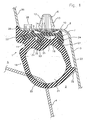
- Fig. 1 shows a sealing arrangement 1 for a gap 2 between a first component 3 and a second component 4.
- the first component 3 is a closing element, e.g. a door or a flap of a motor vehicle.
- the second component 4 is formed in Fig. 1 by an edge of an opening to be closed 5 of the motor vehicle, wherein the edge is part of a sill of the motor vehicle.
- the seal assembly 1 may extend not only as shown in FIG. 1 along the bottom of the door 3, but around the opening 5 around.
- a mounting rail 7 is fixed by spaced-apart clips 6. Since a lower connecting plate 8 of the first component 3 is substantially rectilinear, the mounting rail 7 may be formed two-dimensionally and extruded from plastic.
- plastic e.g. Polyoxymethylene (POM), polyamide (PA) or a thermoplastic elastomer (TPE) having a hardness of 40 to 80 Shore D.
- Support ribs 9 and 10 are formed on a base 11 of the mounting rail 7 and are pulled by resilient legs 12 and 13 of the clip 6, which are supported on an upper side 14 of the terminal plate 8, for abutment against a lower side 15 of the terminal plate 8.
- Each clip 6 is with a sealing plate 16 welded or glued to the base 11.
- Each clip 6 is inserted through a hole 17 in the connecting plate 8 from below until the legs 12, 13 above the upper side 14 can pivot outwards into its operating position. In this operating position, an outer edge of the sealing plate 16 sealingly abuts against the lower side 15 and prevents moisture from passing through the bore 17.
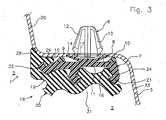
- the seal assembly 1 still has a profile 18 with a holding portion 19 and a sealing portion 20. Transverse to a longitudinal extension of the profile 18 at a distance from each other, the mounting rail 7 is provided with a first latching region 21, a second latching region 22 and a third latching region 23. Each of these latching areas 21 to 23 is formed barb-like. With each latching area 21 to 23 a complementary shaped counter-latching area 24, 25 and 26 of the holding portion 19 can be latched, as shown in Fig. 1 in the final state. The counter-latching areas 24, 25 are combined to form a latching foot 27, which is latched to the first latching area 21 and the third latching area 23.
- the second latching region 22 is formed on an inner longitudinal edge of the mounting rail 7 and arranged at a transverse distance 28 from the inner support rib 9. By the transverse spacing 28, a space is created, in which the counter-latching region 26 of the holding portion 19 are pressed and can snap latching. At this inner counter-locking portion 26, a first sealing lip 29 is formed. The first sealing lip 29 engages sealingly against an ascending projection 30 of the connecting plate 8 when the counter-latching region 26 of FIG. 1 is engaged.
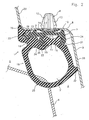
- the sealing region 20 is formed overall tubular with a cavity 31 and formed on the holding portion 19.
- the sealing area 20 carries outside and at a distance from the mounting rail 7, a second sealing lip 32, which cooperates in the mounted state of the seal assembly 1 according to FIG. 1 sealingly with a descending extension 33 of the connecting plate 8.
- This sealing effect increases even more when the door 3 is closed and the sealing area 20 is compressed by the stationary sill 4.
- a solid bead 34 of the holding region 19 adjoins the rear side 35 of the third latching region 23, which is left in FIG. 1. This counteracts unintentional release of the latching foot 27 from its latching with the latching areas 21, 23.
- the procedure is preferably such that initially the mounting rail 7 is fixed either two-dimensionally or three-dimensionally on the first component 3. Then, the latching foot 27 is pressed into the space between the first latching area 21 and the second latching area 22 and latched there. Thereafter, the first sealing lip is pivoted together with the counter-latching region 26 and the counter-latching region 26 is pressed into the space existing in the region of the transverse spacing 28 until the counter-latching region 26 has latched securely to the second latching region 22. Thus, the seal assembly 1 is ready. If the profile 18 has been damaged, it can be removed again from the mounting rail 7 without damaging the mounting rail 7 and replaced by a new profile 18 in the described installation path.
- the profile 18 as a so-called monoprofile completely made of soft rubber hardness of 40 to 70 Shore A.
- the profile 18 may also be completely extruded from TPE of the same hardness. It is important that in these embodiments, a hardness is selected for the profile 18, on the one hand enough tight fit in the holding portion 19 and on the other hand has sufficient elasticity in the sealing region 20 for tolerable closing forces of the door 3.
- the mounting rail has been injection molded three-dimensionally in a molding tool.
- the clips 6 are preferably made of the same plastic as the mounting rail 7 and were molded in the mold to the mounting rail 7.
- the locking foot 27 is made of soft rubber hardness of 50 to 80 Shore A.
- the locking foot could also be made of a suitably hard TPE.
- the remainder of the profile 18 of sponge rubber of a hardness of 15 to 45 Shore A is coextruded together with the locking foot 27.
- a foamed TPE of the same hardness could be used.
- the profile 18 is made of soft rubber of a hardness of 40 to 70 Shore A.
- the mounting rail 7 was in the mold three-dimensionally made of plastic, e.g. TPE, a hardness of 40 to 80 Shore D sprayed.
- the clips were molded with 6 and also the support ribs 9, 10 molded from a relatively soft TPE hardness of 30 to 50 Shore A.
Landscapes
- Engineering & Computer Science (AREA)
- Mechanical Engineering (AREA)
- General Engineering & Computer Science (AREA)
- Seal Device For Vehicle (AREA)
- Gasket Seals (AREA)
- Sealing With Elastic Sealing Lips (AREA)
Claims (11)
- Dispositif d'étanchéité (1) pour une fente (2) entre deux composants (3, 4) coopérant, par exemple un élément de fermeture tel qu'une porte (3) ou un clapet d'un véhicule automobile et un bord (4) d'une ouverture (5) à fermer, dans lequel
un rail de support (7), peut être fixé sur un premier composant (3) des composants (3, 4)
une zone de retenue (19) d'un profilé (18) peut être encliquetée par correspondance de formes avec le rail de support (7),
une zone d'étanchéité (20) du profilé (18) coopérant de manière étanche avec un deuxième (4) des composants (3, 4), est fixée sur la zone de retenue (19),
le rail de support (7) est fabriqué en matière synthétique et présente au moins deux zones d'encliquetage (21 à 23) disposées transversalement à un axe longitudinal du profilé (18), à distance l'une de l'autre,
une zone d'encliquetage antagoniste (24 à 26) formée de manière complémentaire de la zone de retenue (19) peut être encliquetée avec chaque zone d'encliquetage (21 à 23),
et une première (21) et une seconde (22) zones d'encliquetage sont prévues sur des arêtes longitudinales du rail de support (7),
une première lèvre d'étanchéité (29) coopérant de manière étanche avec le premier composant (3) portant le dispositif d'étanchéité (1) étant formée sur une zone d'encliquetage antagoniste (26) intérieure de la zone de retenue (19), et
une seconde lèvre d'étanchéité (32) coopérant de manière étanche avec le premier composant (3) portant le dispositif d'étanchéité (1) étant formée sur la zone d'étanchéité (20) à l'extérieur et à distance du rail de support (7),
caractérisé en ce que la première zone d'encliquetage (21) est formée sur une arête longitudinale extérieure du rail de support (7),
en ce qu'une troisième zone d'encliquetage (23) est disposée transversalement à distance de la première zone d'encliquetage (21), à peu près à mi-largeur du rail de support (7),
et en ce que des zones d'encliquetage antagonistes (24, 25) de la zone de retenue (19) groupées en une base d'encliquetage (27) peuvent être encliquetées avec la première (21) et la troisième zones d'encliquetage (23). - Dispositif d'étanchéité selon la revendication 1,
caractérisé en ce que le rail de support (7) présente une base (11) portant les zones d'encliquetage (21 à 23) et
en ce que la base (11) est appuyée contre le premier composant (3) par le biais de deux nervures-supports (9, 10) distantes transversalement l'une de l'autre et s'étendant parallèlement à l'axe longitudinal du profilé (18). - Dispositif d'étanchéité selon la revendication 2,
caractérisé en ce que la deuxième zone d'encliquetage (22) est formée sur une arête longitudinale intérieure du rail de support (7), et
en ce que la deuxième zone d'encliquetage (22) est disposée transversalement à distance (28) d'une nervure-support (9) intérieure. - Dispositif d'étanchéité selon l'une quelconque des revendications 1 à 3,
caractérisé en ce que le rail de support (7) se compose de polyoxyméthylène (POM) de polyamide (PA) ou d'un élastomère thermoplastique (TPE) d'une dureté de 40 à 80 Shore D. - Dispositif d'étanchéité selon l'une quelconque des revendications 1 à 4,
caractérisé en ce que les nervures-supports (9, 10) se composent de TPE relativement souple d'une dureté de 30 à 50 Shore A et sont formées sur la base (11). - Dispositif d'étanchéité selon l'une quelconque des revendications 2 à 5,
caractérisé en ce que le rail de support (7) présente entre les nervures-supports (9, 10) des clips (6) disposés à distance l'un de l'autre et susceptibles d'être enfoncés par pression au travers d'un perçage (17) respectif, dans le premier composant (3). - Dispositif d'étanchéité selon la revendication 6,
caractérisé en ce que le rail de support (7) est moulé par injection dans un outil de formage, et
en ce que les clips (6) sont en matière synthétique et sont moulés par injection dans l'outil de formage sur le rail de support (7). - Dispositif d'étanchéité selon la revendication 6,
caractérisé en ce que le rail de support est extrudé et
en ce que les clips (6) sont fixés sur le rail de support (7). - Dispositif d'étanchéité selon l'une quelconque des revendications 1 à 8,
caractérisé en ce que la base d'encliquetage (27) en caoutchouc mou ou en un TPE d'une dureté de 50 à 80 Shore A et le reste du profilé (18) en caoutchouc mousse ou en un TPE expansé d'une dureté de 15 à 45 Shore A sont coextrudés. - Dispositif d'étanchéité selon l'une quelconque des revendications 1 à 8,
caractérisé en ce que le profilé (18) en caoutchouc mou ou en un TPE d'une dureté de 40 à 70 Shore A est extrudé. - Dispositif d'étanchéité selon l'une quelconque des revendications 1 à 8,
caractérisé en ce que le profilé (18) en caoutchouc mousse ou en un TPE expansé d'une dureté de 15 à 45 Shore A est extrudé.
Applications Claiming Priority (3)
| Application Number | Priority Date | Filing Date | Title |
|---|---|---|---|
| DE20104747U DE20104747U1 (de) | 2001-03-20 | 2001-03-20 | Spaltdichtungsanordnung |
| DE20104747U | 2001-03-20 | ||
| PCT/EP2002/002628 WO2002078991A1 (fr) | 2001-03-20 | 2002-03-09 | Ensemble joint |
Publications (2)
| Publication Number | Publication Date |
|---|---|
| EP1370436A1 EP1370436A1 (fr) | 2003-12-17 |
| EP1370436B1 true EP1370436B1 (fr) | 2007-12-12 |
Family
ID=7954515
Family Applications (1)
| Application Number | Title | Priority Date | Filing Date |
|---|---|---|---|
| EP02740420A Expired - Lifetime EP1370436B1 (fr) | 2001-03-20 | 2002-03-09 | Ensemble joint |
Country Status (5)
| Country | Link |
|---|---|
| US (1) | US6942225B2 (fr) |
| EP (1) | EP1370436B1 (fr) |
| JP (1) | JP4044847B2 (fr) |
| DE (2) | DE20104747U1 (fr) |
| WO (1) | WO2002078991A1 (fr) |
Families Citing this family (39)
| Publication number | Priority date | Publication date | Assignee | Title |
|---|---|---|---|---|
| DE10214126A1 (de) * | 2002-03-28 | 2003-10-23 | Infineon Technologies Ag | Herstellungsverfahren für eine Mehrzahl von ungefähr gleich hohen und gleich beabstandeten Gatestapeln auf einem Halbleitersubstrat |
| JP3890565B2 (ja) * | 2003-03-14 | 2007-03-07 | 西川ゴム工業株式会社 | ドアウエザーストリップの組付構造 |
| BR0300905B1 (pt) * | 2003-03-28 | 2011-06-28 | sistema de fechamento de filtro de sucção para compressor hermético. | |
| EP1651458B1 (fr) * | 2003-07-24 | 2010-02-03 | Brose Fahrzeugteile GmbH & Co. KG, Coburg | Portiere de vehicule automobile |
| MXPA06009960A (es) * | 2004-03-02 | 2006-12-14 | M Man Tex Ltd | Junta de cubierta. |
| DE102004053610A1 (de) * | 2004-11-02 | 2006-05-04 | Brose Fahrzeugteile Gmbh & Co | Türbaugruppe für eine Kraftfahrzeugtür |
| US7352507B2 (en) * | 2005-05-17 | 2008-04-01 | Infocus Corporation | Screen assembly |
| DE102005024035A1 (de) * | 2005-05-25 | 2006-12-07 | Fahrzeugwerk Bernard Krone Gmbh | Dichtungsvorrichtung |
| FR2896846B1 (fr) * | 2006-02-01 | 2008-05-16 | Hutchinson Sa | Joint d'etancheite dans le domaine de l'industrie automobile ou du batiment par exemple. |
| JP2007256818A (ja) * | 2006-03-24 | 2007-10-04 | Sony Corp | 背面投射型表示装置及び透過型スクリーン |
| JP4972365B2 (ja) * | 2006-08-30 | 2012-07-11 | 鬼怒川ゴム工業株式会社 | 自動車のドアシール構造 |
| DE102006052354A1 (de) * | 2006-11-07 | 2008-05-15 | GM Global Technology Operations, Inc., Detroit | Dichteinrichtung zur Abdichtung einer Tür gegenüber einem Karosserieteil und Kraftfahrzeug mit einer gegen ein Karosserieteil schwenkbaren Tür |
| DE102008020936B4 (de) * | 2007-04-27 | 2016-11-10 | Toyoda Gosei Co., Ltd. | Dichtungsstreifen und Herstellungsverfahren für diesen |
| DE102007045659A1 (de) | 2007-09-25 | 2009-04-02 | Audi Ag | Dichtungsprofil zum Abdichten eines Bereichs zwischen einer Türsäule und einer Seitentür eines Kraftwagens |
| DE102007045656B4 (de) * | 2007-09-25 | 2016-06-16 | Audi Ag | Dichtungsprofil zur Abdichtung eines Bereichs zwischen zwei Bauteilen eines Kraftwagens |
| DE202008013133U1 (de) * | 2008-10-02 | 2010-02-25 | Rehau Ag + Co | Scheibenabdichtung |
| US8419021B2 (en) | 2008-10-31 | 2013-04-16 | Ti Group Automotive Systems, L.L.C. | Ring seal with insert |
| US8919045B2 (en) * | 2008-12-11 | 2014-12-30 | Edwards Industries, Inc. | Bulb seal |
| JP4775457B2 (ja) | 2009-02-27 | 2011-09-21 | ブラザー工業株式会社 | 処理液塗布装置および画像形成装置 |
| DE202009006421U1 (de) | 2009-05-05 | 2009-07-23 | Meteor Gummiwerke K.H. Bädje GmbH & Co. KG | Dichtungsanordnung |
| US9415854B2 (en) | 2011-09-14 | 2016-08-16 | Mitsubishi Aircraft Corporation | Aircraft window and aircraft having an electromagnetic shield |
| JP5060647B1 (ja) * | 2011-09-14 | 2012-10-31 | 三菱航空機株式会社 | 航空機の窓、開口部の閉塞体、ガスケットシール |
| US8875443B2 (en) | 2012-04-13 | 2014-11-04 | TrimLok, Inc. | Flexible seal for recreational vehicles |
| US8701351B2 (en) | 2012-04-13 | 2014-04-22 | Trim-Lok, Inc. | Flexible seal for recreational vehicles |
| US8910422B2 (en) | 2012-04-13 | 2014-12-16 | Trim-Lok, Inc. | Flexible seal for recreational vehicles |
| US9399391B2 (en) | 2014-08-04 | 2016-07-26 | Roll-N-Lock Corporation | Retractable truck bed cover having slat array with flexible joiner members and shielded seams |
| DE102015109795A1 (de) * | 2015-06-18 | 2016-12-22 | Cqlt Saargummi Technologies S.À.R.L. | Dichtungselement aus Elastomermaterial |
| EP3118040A1 (fr) * | 2015-07-15 | 2017-01-18 | AGC Glass Europe | Ensemble de division d'une voiture, assemblage de l'ensemble de division avec une vitre sans cadre et une autre fenêtre adjacente d'une voiture et procédé de fabrication de l'ensemble |
| US10336266B2 (en) | 2016-06-30 | 2019-07-02 | Composite Solutions, Inc. | Interior flange for slide-room |
| US10647187B2 (en) | 2017-04-27 | 2020-05-12 | Lund, Inc. | Tonneau cover |
| DE102018110218A1 (de) * | 2017-06-12 | 2018-12-13 | Cqlt Saargummi Technologies S.À.R.L. | Dichtungsanordnung zur Führung und Abdichtung einer vertikal bewegbaren Fahrzeugfensterscheibe |
| US10457124B2 (en) | 2017-08-18 | 2019-10-29 | Roll-N-Lock Corporation | Modified retractable tonneau cover |
| CN107878162B (zh) * | 2017-11-16 | 2023-12-22 | 建新赵氏科技股份有限公司 | 汽车后车窗导槽模压双道密封结构 |
| US11203896B2 (en) * | 2018-08-07 | 2021-12-21 | Endura Products, Llc | Entryway and weather strip for the same |
| US11220163B2 (en) | 2018-10-26 | 2022-01-11 | Roll-N-Lock Corporation | Vehicle rack assembly |
| US11654978B2 (en) | 2019-11-04 | 2023-05-23 | Lund Motion Products, Inc. | Vehicle rack assembly |
| KR20220136793A (ko) * | 2021-04-01 | 2022-10-11 | 현대자동차주식회사 | 차량용 밀봉구조 |
| US11287044B1 (en) | 2021-06-11 | 2022-03-29 | Trim-Lok, Inc. | Slide seal |
| US11318827B1 (en) | 2021-07-15 | 2022-05-03 | Trim-Lok, Inc. | Bottom pan seal system |
Family Cites Families (20)
| Publication number | Priority date | Publication date | Assignee | Title |
|---|---|---|---|---|
| US3059292A (en) * | 1960-01-28 | 1962-10-23 | Gen Motors Corp | Sealing strip |
| GB992673A (en) | 1963-08-10 | 1965-05-19 | Bright Mfg Co Ltd | Improvements in draught excluding strips for motor vehicles |
| JPS5434897Y2 (fr) * | 1975-03-17 | 1979-10-24 | ||
| US4119325A (en) * | 1977-05-25 | 1978-10-10 | Schlegel (Uk) Limited | Three-part seal construction |
| IT1154448B (it) * | 1982-01-28 | 1987-01-21 | Comind Spa Azienda Ages | Profilato di guarnizione di materia le elastomero particolarmente per carrozzerie di autoveicoli e suo procedimento di fabbricazione |
| DE3342362A1 (de) * | 1983-11-23 | 1985-06-05 | Metzeler Kautschuk GmbH, 8000 München | Vorrichtung zur fuehrung und halterung einer fensterscheibe in einem kraftfahrzeug |
| DE3836687C2 (de) * | 1988-10-28 | 1995-11-09 | Audi Ag | Dachzierleiste für ein Kraftfahrzeug |
| US4916864A (en) * | 1989-05-05 | 1990-04-17 | White Consolidated Industries, Inc. | Snap-in gasket system for refrigerator and freezer doors |
| FR2667672B1 (fr) * | 1990-10-04 | 1993-08-13 | Hutchinson | Joint profile a base d'elastomere, matiere plastique ou analogue, procede de fabrication d'un tel joint et son procede de montage. |
| US5010689A (en) * | 1990-03-19 | 1991-04-30 | The Standard Products Company | Glass run channel |
| JP2981692B2 (ja) * | 1992-03-11 | 1999-11-22 | 西川ゴム工業株式会社 | ウエザーストリップ |
| FR2696377B1 (fr) | 1992-10-05 | 1994-12-23 | Technistan | Joint d'étanchéité pour vitre coulissante de véhicule. |
| US5462292A (en) * | 1992-11-30 | 1995-10-31 | Nishikawa Rubber Co., Ltd. | Door seal device |
| DE29513597U1 (de) * | 1995-08-24 | 1995-10-19 | Baedje K H Meteor Gummiwerke | Kraftfahrzeug-Dichtungsprofil |
| JPH10217771A (ja) * | 1997-01-31 | 1998-08-18 | Nishikawa Rubber Co Ltd | ドア周縁枠部材の構造 |
| US6321490B1 (en) * | 1997-10-01 | 2001-11-27 | Gencorp Inc. | Mechanically interlocked weatherstrip |
| DE29720053U1 (de) * | 1997-11-12 | 1999-03-18 | Baedje K H Meteor Gummiwerke | Dichtungsverbindungselement, Dichtungsendstück und Dichtung |
| DE19912176A1 (de) | 1999-03-18 | 2000-09-21 | Volkswagen Ag | Dichtungsanordnung für ein Bauteil nach Art einer Tür oder Klappe |
| DE19959992C2 (de) | 1999-12-13 | 2001-05-17 | Audi Ag | Vorrichtung zur Befestigung einer Türdichtung, insbesondere einer Türinnendichtung einer Kraftfahrzeugtür |
| DE20006771U1 (de) * | 2000-04-12 | 2001-08-23 | Meritor Automotive Gmbh | Dichtungsanordnung für eine bewegliche und eine angrenzende feststehende Fensterscheibe eines Fahrzeuges |
-
2001
- 2001-03-20 DE DE20104747U patent/DE20104747U1/de not_active Expired - Lifetime
-
2002
- 2002-03-09 EP EP02740420A patent/EP1370436B1/fr not_active Expired - Lifetime
- 2002-03-09 DE DE50211353T patent/DE50211353D1/de not_active Expired - Lifetime
- 2002-03-09 US US10/472,612 patent/US6942225B2/en not_active Expired - Fee Related
- 2002-03-09 JP JP2002577230A patent/JP4044847B2/ja not_active Expired - Fee Related
- 2002-03-09 WO PCT/EP2002/002628 patent/WO2002078991A1/fr active IP Right Grant
Also Published As
| Publication number | Publication date |
|---|---|
| JP4044847B2 (ja) | 2008-02-06 |
| DE50211353D1 (de) | 2008-01-24 |
| WO2002078991A1 (fr) | 2002-10-10 |
| JP2004530085A (ja) | 2004-09-30 |
| US20040094906A1 (en) | 2004-05-20 |
| US6942225B2 (en) | 2005-09-13 |
| EP1370436A1 (fr) | 2003-12-17 |
| DE20104747U1 (de) | 2002-05-02 |
Similar Documents
| Publication | Publication Date | Title |
|---|---|---|
| EP1370436B1 (fr) | Ensemble joint | |
| EP2675639B1 (fr) | Joint d'étanchéité pour connecter un élément à une vitre fixe de véhicule | |
| DE10158401B4 (de) | Moduldach für ein Kraftfahrzeug und Verfahren zu seiner Montage | |
| DE20321549U1 (de) | Dicht-, Trimm- oder Führungsleiste | |
| WO2001085481A1 (fr) | Ensemble joint d'etancheite pour vitres de vehicules | |
| WO1995021749A1 (fr) | Procede de production et de montage d'une vitre avec cadre, notamment dans une partie de vehicule | |
| DE19531167A1 (de) | Kraftfahrzeug-Dichtungsprofil und Verfahren zu seiner Herstellung | |
| EP0347485B1 (fr) | Dispositif sur véhicules automobiles pour l'écoulement d'eau | |
| DE60320276T9 (de) | Dichtungs-, zier- oder führungsstreifen | |
| EP0614775B1 (fr) | Fenêtre pour véhicule | |
| EP1985501A2 (fr) | Ensemble de garniture de véhicule automobile, procédé de montage d'un tel ensemble de garniture et ensemble de véhicule automobile avec un tel ensemble de garniture | |
| DE19543819A1 (de) | Kombiniertes Blenden- und Türdichtungsteil zur Anbringung an einem Kraftfahrzeug | |
| DE10116593B4 (de) | Fahrzeugdach | |
| DE19504828C2 (de) | Verfahren zum Herstellen und Verbinden eines Rahmens mit einer Glasscheibe und Vorrichtung zum Durchführen des Verfahrens | |
| DE102017211291B4 (de) | Fensterschachtleistenanordnung sowie Verfahren zum Herstellen einer Fensterschachtleistenanordnung | |
| DE19845746C2 (de) | Ventil, insbesondere Be- und Entlüftungsventil für den Innenraum eines Kraftfahrzeuges | |
| EP1064164B1 (fr) | Profile d'etancheite pour vehicule automobile | |
| DE19501389C1 (de) | Dachumrandung für ein Schiebe- oder Hubdach aus Glas oder Metall für Kraftfahrzeuge | |
| EP1379404B1 (fr) | Systeme d'etancheite de fente | |
| WO1997028979A1 (fr) | Profile d'etancheite pour vehicule automobile | |
| DE10053678B4 (de) | Anordnung aus einer Fahrzeugfensterscheibe und einem anschließenden Abdeckelement | |
| DE3337438A1 (de) | Profilleiste | |
| DE10008565A1 (de) | Befestigungsclip | |
| EP3711990B1 (fr) | Élément de liaison avec deux dispositifs de maintien indépendants | |
| DE102004028738A1 (de) | Verfahren zur Herstellung eines Dichtungsmoduls für eine Festfensterscheibe und damit erhaltenes Modul |
Legal Events
| Date | Code | Title | Description |
|---|---|---|---|
| REG | Reference to a national code |
Ref country code: SE Ref legal event code: TRGR |
|
| PUAI | Public reference made under article 153(3) epc to a published international application that has entered the european phase |
Free format text: ORIGINAL CODE: 0009012 |
|
| 17P | Request for examination filed |
Effective date: 20030718 |
|
| AK | Designated contracting states |
Kind code of ref document: A1 Designated state(s): AT BE CH CY DE DK ES FI FR GB GR IE IT LI LU MC NL PT SE TR |
|
| RAP1 | Party data changed (applicant data changed or rights of an application transferred) |
Owner name: METEOR GUMMIWERKEK.H. BAEDJE GMBH & CO. KG. |
|
| GRAP | Despatch of communication of intention to grant a patent |
Free format text: ORIGINAL CODE: EPIDOSNIGR1 |
|
| RBV | Designated contracting states (corrected) |
Designated state(s): DE FR GB IT SE |
|
| GRAS | Grant fee paid |
Free format text: ORIGINAL CODE: EPIDOSNIGR3 |
|
| GRAA | (expected) grant |
Free format text: ORIGINAL CODE: 0009210 |
|
| AK | Designated contracting states |
Kind code of ref document: B1 Designated state(s): DE FR GB IT SE |
|
| REG | Reference to a national code |
Ref country code: GB Ref legal event code: FG4D Free format text: NOT ENGLISH |
|
| GBT | Gb: translation of ep patent filed (gb section 77(6)(a)/1977) |
Effective date: 20071224 |
|
| REF | Corresponds to: |
Ref document number: 50211353 Country of ref document: DE Date of ref document: 20080124 Kind code of ref document: P |
|
| ET | Fr: translation filed | ||
| PLBE | No opposition filed within time limit |
Free format text: ORIGINAL CODE: 0009261 |
|
| STAA | Information on the status of an ep patent application or granted ep patent |
Free format text: STATUS: NO OPPOSITION FILED WITHIN TIME LIMIT |
|
| 26N | No opposition filed |
Effective date: 20080915 |
|
| PGFP | Annual fee paid to national office [announced via postgrant information from national office to epo] |
Ref country code: GB Payment date: 20090324 Year of fee payment: 8 |
|
| PGFP | Annual fee paid to national office [announced via postgrant information from national office to epo] |
Ref country code: IT Payment date: 20090326 Year of fee payment: 8 Ref country code: SE Payment date: 20090325 Year of fee payment: 8 |
|
| PGFP | Annual fee paid to national office [announced via postgrant information from national office to epo] |
Ref country code: FR Payment date: 20090318 Year of fee payment: 8 |
|
| EUG | Se: european patent has lapsed | ||
| GBPC | Gb: european patent ceased through non-payment of renewal fee |
Effective date: 20100309 |
|
| REG | Reference to a national code |
Ref country code: FR Ref legal event code: ST Effective date: 20101130 |
|
| PG25 | Lapsed in a contracting state [announced via postgrant information from national office to epo] |
Ref country code: FR Free format text: LAPSE BECAUSE OF NON-PAYMENT OF DUE FEES Effective date: 20100331 |
|
| PG25 | Lapsed in a contracting state [announced via postgrant information from national office to epo] |
Ref country code: IT Free format text: LAPSE BECAUSE OF NON-PAYMENT OF DUE FEES Effective date: 20100309 Ref country code: GB Free format text: LAPSE BECAUSE OF NON-PAYMENT OF DUE FEES Effective date: 20100309 |
|
| PG25 | Lapsed in a contracting state [announced via postgrant information from national office to epo] |
Ref country code: SE Free format text: LAPSE BECAUSE OF NON-PAYMENT OF DUE FEES Effective date: 20100310 |
|
| REG | Reference to a national code |
Ref country code: DE Ref legal event code: R082 Ref document number: 50211353 Country of ref document: DE Representative=s name: RAINER CALLIES, DE Ref country code: DE Ref legal event code: R082 Ref document number: 50211353 Country of ref document: DE Representative=s name: CALLIES, RAINER, DIPL.-PHYS. DR.RER.NAT., DE |
|
| REG | Reference to a national code |
Ref country code: DE Ref legal event code: R082 Ref document number: 50211353 Country of ref document: DE Representative=s name: CALLIES, RAINER, DIPL.-PHYS. DR.RER.NAT., DE |
|
| REG | Reference to a national code |
Ref country code: DE Ref legal event code: R082 Ref document number: 50211353 Country of ref document: DE Representative=s name: CALLIES, RAINER, DIPL.-PHYS. DR.RER.NAT., DE Effective date: 20141029 Ref country code: DE Ref legal event code: R082 Ref document number: 50211353 Country of ref document: DE Representative=s name: CALLIES, RAINER, DIPL.-PHYS. DR.RER.NAT., DE Effective date: 20121008 Ref country code: DE Ref legal event code: R081 Ref document number: 50211353 Country of ref document: DE Owner name: TOYODA GOSEI METEOR GMBH, DE Free format text: FORMER OWNER: METEOR GUMMIWERKE K. H. BAEDJE GMBH & CO. KG, 31167 BOCKENEM, DE Effective date: 20141029 |
|
| PGFP | Annual fee paid to national office [announced via postgrant information from national office to epo] |
Ref country code: DE Payment date: 20150328 Year of fee payment: 14 |
|
| REG | Reference to a national code |
Ref country code: DE Ref legal event code: R119 Ref document number: 50211353 Country of ref document: DE |
|
| PG25 | Lapsed in a contracting state [announced via postgrant information from national office to epo] |
Ref country code: DE Free format text: LAPSE BECAUSE OF NON-PAYMENT OF DUE FEES Effective date: 20161001 |