EP2675639B1 - Joint d'étanchéité pour connecter un élément à une vitre fixe de véhicule - Google Patents
Joint d'étanchéité pour connecter un élément à une vitre fixe de véhicule Download PDFInfo
- Publication number
- EP2675639B1 EP2675639B1 EP12770034.2A EP12770034A EP2675639B1 EP 2675639 B1 EP2675639 B1 EP 2675639B1 EP 12770034 A EP12770034 A EP 12770034A EP 2675639 B1 EP2675639 B1 EP 2675639B1
- Authority
- EP
- European Patent Office
- Prior art keywords
- profile
- closure
- closure element
- profile element
- latching
- Prior art date
- Legal status (The legal status is an assumption and is not a legal conclusion. Google has not performed a legal analysis and makes no representation as to the accuracy of the status listed.)
- Active
Links
- 238000007789 sealing Methods 0.000 title claims description 13
- 238000005304 joining Methods 0.000 title description 6
- 239000000463 material Substances 0.000 claims description 30
- 230000007704 transition Effects 0.000 claims description 9
- 239000012790 adhesive layer Substances 0.000 claims description 4
- 230000002787 reinforcement Effects 0.000 claims 1
- XLYOFNOQVPJJNP-UHFFFAOYSA-N water Substances O XLYOFNOQVPJJNP-UHFFFAOYSA-N 0.000 description 64
- 238000001125 extrusion Methods 0.000 description 11
- 238000000034 method Methods 0.000 description 9
- 238000009434 installation Methods 0.000 description 8
- 229920001971 elastomer Polymers 0.000 description 6
- 230000002349 favourable effect Effects 0.000 description 6
- 238000004519 manufacturing process Methods 0.000 description 6
- 230000003014 reinforcing effect Effects 0.000 description 6
- 238000005452 bending Methods 0.000 description 5
- 238000003780 insertion Methods 0.000 description 5
- 230000037431 insertion Effects 0.000 description 5
- 230000001681 protective effect Effects 0.000 description 5
- 239000000853 adhesive Substances 0.000 description 4
- 230000001070 adhesive effect Effects 0.000 description 4
- 239000000428 dust Substances 0.000 description 4
- 229920002725 thermoplastic elastomer Polymers 0.000 description 4
- 239000002390 adhesive tape Substances 0.000 description 3
- 239000011324 bead Substances 0.000 description 3
- 230000000694 effects Effects 0.000 description 3
- 239000013013 elastic material Substances 0.000 description 3
- 230000003716 rejuvenation Effects 0.000 description 3
- 238000003860 storage Methods 0.000 description 3
- 235000001674 Agaricus brunnescens Nutrition 0.000 description 2
- 239000004743 Polypropylene Substances 0.000 description 2
- XECAHXYUAAWDEL-UHFFFAOYSA-N acrylonitrile butadiene styrene Chemical compound C=CC=C.C=CC#N.C=CC1=CC=CC=C1 XECAHXYUAAWDEL-UHFFFAOYSA-N 0.000 description 2
- 229920000122 acrylonitrile butadiene styrene Polymers 0.000 description 2
- 239000004676 acrylonitrile butadiene styrene Substances 0.000 description 2
- 230000015572 biosynthetic process Effects 0.000 description 2
- 238000011109 contamination Methods 0.000 description 2
- 239000000806 elastomer Substances 0.000 description 2
- 239000004033 plastic Substances 0.000 description 2
- 229920003023 plastic Polymers 0.000 description 2
- 229920001155 polypropylene Polymers 0.000 description 2
- 238000003825 pressing Methods 0.000 description 2
- 229920002943 EPDM rubber Polymers 0.000 description 1
- 230000001154 acute effect Effects 0.000 description 1
- 238000004026 adhesive bonding Methods 0.000 description 1
- 230000009286 beneficial effect Effects 0.000 description 1
- 239000000356 contaminant Substances 0.000 description 1
- 230000001934 delay Effects 0.000 description 1
- 238000000151 deposition Methods 0.000 description 1
- 238000005516 engineering process Methods 0.000 description 1
- 239000000835 fiber Substances 0.000 description 1
- 239000003292 glue Substances 0.000 description 1
- 238000001746 injection moulding Methods 0.000 description 1
- 239000005340 laminated glass Substances 0.000 description 1
- 239000002184 metal Substances 0.000 description 1
- 239000002245 particle Substances 0.000 description 1
- 230000035515 penetration Effects 0.000 description 1
- -1 polypropylene Polymers 0.000 description 1
- 239000004800 polyvinyl chloride Substances 0.000 description 1
- 238000004064 recycling Methods 0.000 description 1
- 239000013589 supplement Substances 0.000 description 1
- 229920001169 thermoplastic Polymers 0.000 description 1
- 229920001187 thermosetting polymer Polymers 0.000 description 1
- 239000004416 thermosoftening plastic Substances 0.000 description 1
Images


Classifications
-
- B—PERFORMING OPERATIONS; TRANSPORTING
- B60—VEHICLES IN GENERAL
- B60J—WINDOWS, WINDSCREENS, NON-FIXED ROOFS, DOORS, OR SIMILAR DEVICES FOR VEHICLES; REMOVABLE EXTERNAL PROTECTIVE COVERINGS SPECIALLY ADAPTED FOR VEHICLES
- B60J10/00—Sealing arrangements
- B60J10/30—Sealing arrangements characterised by the fastening means
- B60J10/34—Sealing arrangements characterised by the fastening means using adhesives
-
- B—PERFORMING OPERATIONS; TRANSPORTING
- B60—VEHICLES IN GENERAL
- B60J—WINDOWS, WINDSCREENS, NON-FIXED ROOFS, DOORS, OR SIMILAR DEVICES FOR VEHICLES; REMOVABLE EXTERNAL PROTECTIVE COVERINGS SPECIALLY ADAPTED FOR VEHICLES
- B60J10/00—Sealing arrangements
- B60J10/45—Assembling sealing arrangements with vehicle parts
-
- B—PERFORMING OPERATIONS; TRANSPORTING
- B60—VEHICLES IN GENERAL
- B60J—WINDOWS, WINDSCREENS, NON-FIXED ROOFS, DOORS, OR SIMILAR DEVICES FOR VEHICLES; REMOVABLE EXTERNAL PROTECTIVE COVERINGS SPECIALLY ADAPTED FOR VEHICLES
- B60J10/00—Sealing arrangements
- B60J10/15—Sealing arrangements characterised by the material
- B60J10/18—Sealing arrangements characterised by the material provided with reinforcements or inserts
-
- B—PERFORMING OPERATIONS; TRANSPORTING
- B60—VEHICLES IN GENERAL
- B60J—WINDOWS, WINDSCREENS, NON-FIXED ROOFS, DOORS, OR SIMILAR DEVICES FOR VEHICLES; REMOVABLE EXTERNAL PROTECTIVE COVERINGS SPECIALLY ADAPTED FOR VEHICLES
- B60J10/00—Sealing arrangements
- B60J10/20—Sealing arrangements characterised by the shape
-
- B—PERFORMING OPERATIONS; TRANSPORTING
- B60—VEHICLES IN GENERAL
- B60J—WINDOWS, WINDSCREENS, NON-FIXED ROOFS, DOORS, OR SIMILAR DEVICES FOR VEHICLES; REMOVABLE EXTERNAL PROTECTIVE COVERINGS SPECIALLY ADAPTED FOR VEHICLES
- B60J10/00—Sealing arrangements
- B60J10/30—Sealing arrangements characterised by the fastening means
-
- B—PERFORMING OPERATIONS; TRANSPORTING
- B60—VEHICLES IN GENERAL
- B60J—WINDOWS, WINDSCREENS, NON-FIXED ROOFS, DOORS, OR SIMILAR DEVICES FOR VEHICLES; REMOVABLE EXTERNAL PROTECTIVE COVERINGS SPECIALLY ADAPTED FOR VEHICLES
- B60J10/00—Sealing arrangements
- B60J10/70—Sealing arrangements specially adapted for windows or windscreens
Definitions
- the invention relates to a profile element for connecting a component to a vehicle window according to the preamble of claim 1 and to a sealing arrangement according to claim 20.
- a component with a vehicle window located at the bottom of a windshield usually a water tank or a water tank cover that is collected by the windshield dissipating water and dissipate laterally.
- a profile element located at the edge with the vehicle window and the releasably receiving the water box cover has a locking groove.
- the water box cover is provided with a rib which is positively and / or positively received by the locking groove, so that the cover can be removed and mounted repeatedly if necessary.
- profile elements are, for example, in DE 199 61 706 A1 .
- DE 20 2008 006 986 U1 or DE 20 2008 016 217 U1 apparently.
- the locking elements are made of a soft elastic material. When inserting a mushroom-shaped strip, the locking elements deform elastically and then engage behind the mushroom head. The strip is then fixed in the recess.
- Deviating from this disclosed DE 20 2008 006 986 U1 only an elastically deformable latching element which projects into the latching recess. Opposite a substantially inelastic locking nose is arranged. When inserting a mushroom-shaped bar essentially deviates only the elastic locking element. In the end position then grip the locking lug and the elastic locking element behind the mushroom head.
- the profile elements usually produced by extrusion are elongated profile strands with a longitudinal direction and a cross section adapted perpendicular to the respective disc profile. Before mounting or gluing to the windscreen, they must be adjusted by bending the respective edge of the windscreen edge. In this case, provided with relatively tight tolerance requirements locking grooves can deform so far that a joining of the water tank cover is difficult or impossible no longer possible. The same danger exists when mounting a profile element on the pane, in particular when a U-shaped profile element has to be pressed onto the edge of the pane.
- each profile element is usually connected prior to installation of the vehicle window in the vehicle with its lower edge and that the discs are transported because of their brittleness usually standing on the lower edge. Alone due to the weight of the vehicle windows, therefore, deformations within the profile elements can hardly be avoided, so that problems occur later when snapping the water tank cover into the locking groove.
- Kederangn that are temporarily used with a core portion in the locking groove or the recess of the profile element. The latter is thereby protected during manufacture, further processing and / or during transport of the vehicle windows, and the relatively sensitive locking groove can neither be polluted nor deformed.
- Kederangn is for example made WO 2006 002 891 A2 . DE 10 2006 038 013 A1 . FR 2 945 521 A1 or US Pat. No. 7,870,958 B1 known.
- the Kederarchn often can only with difficulty remove from the locking grooves or recesses, because the profile elements are bent along the edge of the window and because usually an undercut for the rib of the water box cover is formed. As a result, the core portion is locked or clamped in the Kedermann and the necessary force and time to pull out the also bent Kederance from the profile element is correspondingly large. Moreover, damage to the profile element may occur during the removal of the welt strip, especially if inappropriate tools such as screwdrivers or pliers are used. This also adds additional time and costs.
- the aim of the invention is to overcome these and other disadvantages of the prior art and to provide a profile element for connecting a component with a vehicle window, which is protected both from contamination and from deformation or damage. It should also be constructed inexpensively with simple means and ensure an always reliable and rapid connection of the component with the vehicle window.
- a profile element for connecting a component with a vehicle window with a profile body, which can be fixed with a first portion on an edge of the vehicle window, and which has a latching recess with an engagement opening in a second portion for releasably securing the component to the profile element extends in the longitudinal direction of the profile element and in which a rib of the component non-positively and / or positively fixed
- the invention provides that on the profile body, a closure element is formed, which bridges the engagement opening in a first functional position and closes the recess.
- a closure element on the profile body has the advantage that the locking recess is always reliably protected against the ingress of dirt both during assembly of the profile element at the edge of the vehicle window and during transportation or storage of the already provided with a profile element vehicle windows. If the closure element for the engagement of the component is opened or removed after assembly of the vehicle window in the motor vehicle, the rib of the component can reliably engage in the recess at any time because it is no longer blocked by dust or other dirt.
- profile body in its closed position, the profile body and thus the locking recess stabilizes and supports. As long as therefore the latching recess is closed by the closure element, the latching recess can neither be deformed nor damaged, and this without the use of a separate Kedermann.
- the profile element can thus be adapted, for example, without problems prior to assembly by bending the contour of the vehicle window.
- the tight tolerance requirements for the recess are always met exactly by the closure element. Even during assembly of the profile element on the edge of the vehicle window, the gap dimensions of the recess remain through the closure element over the entire length of the profile element, even if the profile must be pressed with higher forces on the edge of the disc.
- vehicle windows can be transported upright on the profile element and stored.
- the locking element closing the locking recess reliably protects the profile body from deformations or damage.
- the closure element is opened and the component can be mounted quickly and conveniently, because the tolerance dimensions of the recess are exactly maintained over the entire length of the profile.
- Keder- or protective strips which are elaborately introduced into this before further processing and / or mounting the profile elements and must be removed before the installation of the water tank cover with much effort and effort, are no longer necessary, which is not only beneficial to the Production costs affects.
- the handling of the profile elements is significantly simplified because complete assembly and handling steps are eliminated without replacement.
- the removed Keder- or protective strips no longer have to be disposed of consuming, which also has a favorable effect on the total cost.
- the profile body according to the invention With the determination of the profile body according to the invention at the edge of the vehicle window, it is therefore at any time quickly and conveniently possible to connect an adjacent component with the vehicle window by the formed on the component rib is inserted after opening the closure element in the recess of the profile body.
- the non-positive and / or positive connection ensures that the component is always reliably and tightly secured to the disc and can not be inadvertently detached from the profile body or from the disc, for example, during operation of the vehicle.
- the closure element is connected to the profile body along the longitudinal direction of the profile element. This makes it possible to produce the profile elements in the extrusion process, which also has a favorable effect on the production costs.
- the longitudinal direction of the profile element corresponds in this case to the extrusion direction.
- closure element closes the engagement opening of the latching recess in a first functional position and releases it in a second functional position.
- first functional position that fulfills Closure element has two functions: it protects the recess from the ingress of contaminants and it protects the recess in its capacity as a support element against deformation by external forces acting on the profile body forces.
- second functional position however, the rib of the component can freely penetrate into the latching recess and lock there with the profile body.
- the closure element is a planar element whose plane is oriented substantially perpendicular to the edge of the vehicle window.
- the closure element can always reliably and tightly close the latching recess.
- the closure element lies with its plane approximately in the plane of the vehicle window, so that forces acting on the profile element parallel to the vehicle window are always reliably absorbed by the closure element. In its first functional position, this therefore simultaneously forms a support element which temporarily stabilizes the latching recess. If, however, one presses perpendicular to the plane of the closure element in the recess - be it by means of a tool or with the rib of the component - then the closure element is urged to the side. It passes from the first functional position to the second functional position, and the rib can be reliably fixed in the latching recess.
- the invention further provides that a hinge region is formed between the profile body and the closure element.
- a hinge region is formed between the profile body and the closure element.
- This can be formed by a material taper, for example in the manner of a film hinge. But it is also possible to use a transition region between the profile body and the closure element, which consists of another, if necessary, softer or more elastic material. If different materials are used in the profile body, this can advantageously be produced in the coextrusion process.
- the closure element is integral with the profile body or it is cohesively connected to the profile body.
- the closure element only one element must always be manufactured, which has a very favorable effect on the manufacturing costs and logistics. In particular, the costly removal and disposal of separate Kederangn is no longer necessary.
- the profile body and the closure element can either be made of the same material or one uses different materials.
- the profile body consist of a harder material
- the closure element is made of a softer material or vice versa. It is always important that the closure element in the first functional position has a sufficient support effect for the profile body or for the recess and reliably passes into the second functional position during opening and / or when introducing the rib of the component in the recess.
- a single closure element is provided, which is articulated along the longitudinal direction of the profile element on a first side of the latching recess on the profile body.
- the closure element along the longitudinal direction of the profile element in the first functional position non-positively and / or positively engages the profile body in engagement.
- a variant of this embodiment provides that the closure element is connected along the longitudinal direction of the profile element on the first side opposite the second side of the latching recess in the first functional position via a tapered trained area with the profile body.
- This rejuvenated trained Range is dimensioned such that a kind of predetermined breaking point arises. This first holds the closure element in its closed and support position (first functional position). Once the connection between the closure element and the profile body is separated or broken, the closure element enters the second functional position and the rib of the water box cover can be defined in the recess.
- two closure elements are provided, along the longitudinal direction of the profile element, a first closure element on a first side of the latching recess and a second closure element on the first side opposite the second side of the latching recess is articulated to the profile body.
- the closure element is therefore a total of two parts and opens on both sides of the extrusion or longitudinal direction of the profile element.
- closure element In order to lock or to hold the closure elements in the first functional position, these are non-positively and / or positively engaged with each other.
- closure element can also be connected to one another in a variant of this embodiment via a tapered region, preferably a predetermined breaking point.
- At least one closure element in the second functional position can be locked within the latching recess.
- closure element or elements for fixing the rib of the component in the latching recess in that the closure element is designed such that it has or forms a latching element for the rib of the component in the second functional position.
- the stability of the connection between the component and the vehicle window can be further increased.
- closure element itself acts as a latching element and engages with the rib of the component in a non-positive and / or positive engagement.
- closure element can also have or carry at least one latching element, which in the second functional position engages positively and / or positively with the rib of the component.
- a further variant of the invention provides that a latching element for the rib of the component is formed within the latching recess.
- This can be a separate or additional locking element.
- the separate or additional latching element can also be identical to the latching element provided on the closure element.
- the latching element of the closure element and / or the latching element formed within the latching recess form a barb in relation to the rib of the component.
- the closure element is connected to the profile body along tapered regions along the longitudinal direction of the profile element.
- no hinges or joints are now used to pivot the closure element or elements from the first functional position to the second functional position.
- the rejuvenated trained areas rather form predetermined breaking points, which break up during insertion of the rib of the component in the recess and thus allow the locking of the rib with the profile body.
- the first portion of the profile element is L-shaped, wherein the first portion of the profile body has a profile leg which is glued to the lower edge of the vehicle window, for example by means of an adhesive layer or a glue bead.
- the profile element is glued in this embodiment with the profile leg on the underside of the vehicle window, which does not protrude beyond the surface of the vehicle window due to the L-shape.
- the first section of the profile element U-shaped is then plugged onto the vehicle window, wherein the profile body engages over the edge region of the vehicle window with its legs.
- the invention further provides that the profile body has or carries a sealing lip.
- This can be within the U-shaped profile element, be formed as an extension on a leg of the U-profile or - when using a profile element with a cross-sectionally L-shaped first section - be designed such that between the vehicle window and the component a smooth and flush transition arises.
- At least one stiffening insert is provided at least in sections.
- the material properties for the profile element can be varied individually.
- the stiffening insert for example, a metal insert as a hinge between the profile body and the closure element.
- the hinge area and deposits of fiber webs, tissues or the like can be provided, which give the closure element a particularly good mobility of the first to the second functional position.
- the profile element With the profile element according to the invention, it is possible to provide a sealing arrangement for the transition between a vehicle window and a component, especially for the lower part of a motor vehicle windshield, which dispenses entirely with separate Keder- or support strips. Nevertheless, the profile element is reliably protected in the region of the most sensitive recess against the ingress of dirt and damage, because by the formed on the profile body closure element is formed in the region of the recess a kind of hollow profile that holds even larger forces easily. If, however, the closure element is opened by being brought from its first functional position into a second functional position, the component to be attached can be quickly and reliably locked to the profile element with its rib.
- Fig. 1 shows a vehicle window 90, in particular a windscreen for a (not shown) motor vehicle.
- a generally designated 10 profile element is mounted at the lower edge 92 of the windshield 90 .
- This is used to connect a (not shown here) component 80 with the vehicle window 90.
- the latter is usually delivered pre-assembled with the profile element and firmly installed in the body of the vehicle, preferably glued.
- the component 80 may be, for example, a water box cover which is latched in the profile element 10 with a rib 82 (likewise not visible here) in such a way that a tight and stable connection is created which can also be released again if necessary.
- the profile element 10 also other components 80 can be connected to the vehicle window 90, for example another body part, such as e.g. a door frame, a window frame, a trim panel or a cover, which are each to be connected to a permanently installed vehicle window.
- the vehicle window itself may be a front window, but also a roof, rear or side window.
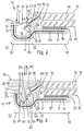
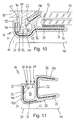
- a first embodiment of a profile element according to the invention is in Fig. 2 shown.
- This is to connect a windshield 90 made of laminated glass with a water box cover 80, which is usually made of plastic.
- the water box cover 80 connects with an upper edge 83 to the most curved lower edge 92 of the windshield 90 and leads from this effluent water to the outside.
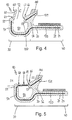
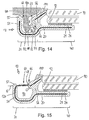
- the outer surface 84 of the water box 80 is - as in Fig. 3 shown - substantially flush with the outer surface 94 of the windshield 90th
- the profile element 10 is preferably an extruded profile, which is produced by extrusion.
- the resulting profile strand extends in the direction of extrusion R, which is identical to the longitudinal direction L of the profile element 10.
- the profile element 10 Transversely to the longitudinal direction L, the profile element 10 has a cross section which is adapted to the particular needs of the installation situation, for example, depending on the dimensions and geometries the water box cover 80 and / or the windshield 90th
- Each profile element 10 is cut to the width of the windshield 90 or to the width of the water box cover 80 and rear side, i. the vehicle interior, glued to the disc 90. It consists of one or more plastics (thermoplastics or thermosets) each having a suitable hardness, for example polypropylene (PP), polyvinyl chloride (PVC), acrylonitrile-butadiene-styrene copolymers (ABS) or the like. and / or combinations thereof. However, it is also possible to use elastomers or rubber materials such as e.g. EPDM.
- PP polypropylene
- PVC polyvinyl chloride
- ABS acrylonitrile-butadiene-styrene copolymers
- elastomers or rubber materials such as e.g. EPDM.
- a first section 40 of the profile element 10 is formed overall approximately L-shaped. He has laying down on the vehicle window 90 a profile leg 21 having a substantially planar surface 23. On this, an adhesive layer 24 is applied in the form of a double-sided adhesive tape, which may be heat-activated, for example. The profile leg 21 is pressed with the adhesive tape 24 along the edge of the disk 92 on the back 95 of the vehicle window 90 and glued to it. You can supplement the profile leg 21 additionally or alternatively with a bead of adhesive to the disc 90 stick. Such a bead of adhesive (not shown) may also partly overlap the profile limb 21.
- the profile element 10 also has a second portion 30, which for releasable attachment of the water box cover 80 has a latching recess 50 which extends in the longitudinal direction L of the profile element 10, the water box cover 80 is provided with a likewise extending in the longitudinal direction L of the profile element 10 rib 82 is, the non-positive and / or positive locking in the recess 50 can be fixed.
- the rib 82 extends in a direction R1 which is approximately perpendicular to the longitudinal direction L and perpendicular to the outer surface 84 of the water box cover 80 and the outer surface 94 of the front pane 90, respectively.
- the arrangement of the vehicle window 90, profile element 10 and water box cover 80 is further made such that the usually resilient Rib 82 of the water box cover 80 in the direction R1 in the recess 50 of the profile element 10 can be inserted and in the opposite direction R2 with increased force again from the profile element 10 is releasable.
- the latching recess 50 is bounded by a substantially L-, U- or hook-shaped spring leg 54 and a support rib 56 which is formed in the transition between the first portion 40 and the second portion 30 of the profile element 10.
- the free end 55 of the spring leg 54 and the support rib 56 thereby form an engagement opening 52 for the rib 82 of the water box cover 80.
- FIGS. 2 and 3 in this case lies the spring leg 54 along the longitudinal direction L of the profile element 10 with its free end 55 on a first side S1 of the recess 50, while the support rib 56 along the longitudinal direction L of the profile element 10 is located on a second side S2, which - based on the engagement opening 52 is located opposite the first side S1 of the latching recess 50.
- the support rib 56 forms between the lower edge 92 of the disc 90 and the inwardly projecting rib 82 of the water box cover 80, a clamping or supporting body which carries a sealing member 110 on a surface 57.
- the latter is preferably made of a flexible material, for example a thermoplastic elastomer (TPE), a sponge rubber or other suitable material, e.g. an elastomer or rubber material.
- the sealing element 110 is preferably integrally connected to the support rib 56. But it can also be integrally formed with this.
- the support rib 56 and the profile limb 21 essentially form the L-shaped cross section of the first section 40 of the profile element 10, wherein a cavity 58 is formed in the region of the disk edge 92.
- the mounted in Position against the disc 90 supporting support rib 56 elastically yield. This in turn ensures not only a permanently good and reliable seal.
- the support rib 56 and the sealing lip 110 can also compensate for tolerances between the disc 90 and the water box cover 80.
- the spring leg 54 carries at its free end 55 a along the longitudinal direction L of the profile element 10 extending closure member 60 which is integrally formed on the profile body 20 and in the in Fig. 2 Functional position designated A, the locking recess 50 and the engagement opening 52 closes.
- a hinge region 61 is formed on the first side S1 of the latching recess 50.
- These are for example - as in the FIGS. 2 and 3 shown - around a tapered material region, which allows pivoting of the closure element 60 about an axis parallel to the longitudinal direction L of the profile element 10, so that the closure element 60 of the in Fig. 2 shown functional position A in an in Fig. 3 shown functional position B can be pivoted.
- the material thickness of the profile body 20 in the hinge region 61 is selected such that the closure element 60 can pivot relatively easily, but still remains stable in itself.
- the closure element 60 along the longitudinal direction L of the profile element 10 is non-positively and / or positively connected to the profile body 20 into engagement.
- a latching region 66 is formed in the support rib 56, which - based on the profile leg 21 of the profile body 20 - is approximately at the same height as the hinge region 61.
- the latching region 66 is preferably formed by a latching recess 67, which also extends in the longitudinal direction L of the profile element 10 extends.
- the closure element 60 engages with its free edge 69 non-positively and / or positively in the latching recess 67, so that the engagement opening 52 of the latching recess 50 is initially closed over the entire length of the profile element 10.
- the closure element 60 is a substantially planar element whose plane E in the functional position A is oriented approximately perpendicularly to the lower edge 92 of the vehicle window 90, ie the plane E of the closure element 60 and the outer surface 94 of the vehicle window 90 lie at least in the edge region of the vehicle Disc 90 about parallel to each other.
- the closure element 60 is hinged on the first side S1 in the hinge region 61 to the spring leg 54 of the profile body 20, while the opposite free edge 69 releasably engages in the latching recess 67 of the support rib 56.
- closure element 60 as a kind of cover the recess 50 and the latter is - as long as the closure member 60 is in the functional position A - reliably protected from the ingress of dirt and dust.
- the closure element 60 bridges the engagement opening 52 of the latching recess 50 in the functional position A, so that the spring leg 54 can be supported with its free end 55 via the closure element 60 on the support rib 56 of the profile body 20.
- This has the following effect: is the profile body 20 - during assembly of the profile element 10 or during storage or handling of the vehicle window 90 - applied in the region of the spring leg 54 with a force prevents the closure member 60 that the spring leg 54 is pressed and the latching recess 50th is deformed.
- the closure element 60 thus forms a kind of support, which gives the profile element 10 in the second section 30 a hollow cross-section.
- the profile element 10 receives a very high overall stability and it is even possible to park the vehicle window 90 with its entire weight edgewise on the profile element 10 without the locking recess 50 is deformed or the spring leg 54 is damaged.
- the closure element 60 directs the force acting on the spring leg 54 directly into the support rib 56, which is supported on the rear side of the edge of the vehicle window 90.
- the latching area 66 on the profile body 20 ensures that the closure element 60 can not laterally escape or buckle away, but remains in the functional position A.
- the opening of the latching recess 50 can take place via a tool (not shown) with which the closure element 60 is pressed into the latching recess 50.
- a tool not shown
- the edge 69 of the closure element 60 is released from the latching recess 67 in the support rib 56 and the closure element 60 pivots inwards.
- the rib 82 of the water box cover 80 for opening the latching recess 50 by simply placing it on the closure element 60 and pushing it inwards into the latching recess 60.
- the closure element is released from the latching region 66 of the support rib 56. It reaches its second functional position B and the rib 82 can engage in the profile element 10.
- the opening of the recess 50 and the setting of the water box cover 80 thus takes place in only one operation, which has an extremely favorable effect on the handling of the profile element 10. A separate Kedermann must not be removed from the profile element 10 nor disposed of.
- the closure element 60 may - in an alternative embodiment to the latching portion 66 formed in the support rib 56 - along the longitudinal direction L of the profile element 10 on the first side S1 opposite second side S2 of the recess 50 in the first functional position A via a (not More specifically designated) tapered trained area with the profile body 20 integrally connected.
- This tapered trained area is designed such that it securely fixes the closure element 60 in the functional position A, while it breaks into the locking recess 50 upon penetration of a tool or the rib 82 of the water box cover 80 and so pivoting the closure element 60 in the functional position B. allows.
- a locking element 100 is provided for the non-positive and / or positive locking of the rib 82 in the recess 50.
- This can - as in the FIGS. 2 and 3 shown - may be formed as a rib extending in the longitudinal direction L of the profile element 10. It is an at least partially elastically deformable body, the coextrusion of a soft elastic material, such as a thermoplastic elastomer (TPE), a sponge rubber or other suitable material, manufactured and arranged and arranged such that the insertion of the rib 82nd the water box cover 80 in the recess 50 in the joining direction R1 with relatively little effort is possible, while the withdrawal of the rib 82 from the recess 50 in the opposite direction R2 is much more difficult.
- TPE thermoplastic elastomer
- the locking element 100 is within the recess 50 at an angle ⁇ to the direction R1, R2 and thus at an acute angle to the rib 82 of the water box cover 80. It also protrudes at least partially into the engagement opening 52 of the recess 50 and is within this non-positively and / or positively with the rib 82 of the water box cover 80 engageable, so that the latter is permanently fixed but releasably fixed in the mounted position.
- the detent member 100 may be provided with a cambered or nose edge at its free longitudinal edge (not specified), while the rib 82 of the faucet cover 80 is provided with an associated nose edge 85 and an undercut (not specified).
- the free end of the latching element 100 or its arched or nose edge can be supported in the mounted position of the water box cover 80 at its rib 82, so that a permanently fixed and stable latching is ensured.
- the locking element 100 is as well as the sealing element 110 fixed to the support rib 56 and in the region of an undercut 59. It may also have a tapered trained middle portion between its connection region on the support rib 56 and the end formed camber or nose edge, so that a approximately concave cross-sectional area results. This allows the locking element 100 laterally or transversely to the longitudinal direction to escape, as soon as the rib 82 of the water box cover 80 is inserted into the recess 50. To assist this effect, the rib 82 of the water box cover 80 is provided at the end with an inclined surface or flank 86, which can push the locking element 100 to the side.
- the locking element 100 in cross section also be formed wedge or cuboid.
- the locking element 100 can also be made at least in sections or alternatively from different materials.
- the nose edge of the detent element 100 may be made of a harder material than the central portion.
- the locking element 100 is - as well as the sealing element 110 - preferably cohesively connected to the support rib 56. But it can also be integrally formed with this.
- Fig. 3 One recognizes in Fig. 3 in that the rib 82 of the water box cover 80, when inserted into the latching recess 50, initially releases the latching element 60 held by the latching area 66 and its latching recess 67 in the functional position A and pivots inwards. In this case, the closure element 60 pushes past the latching element 100. Subsequently, the rib 82 pushes the latching element 100, which projects into the engagement opening 52 of the latching recess 50 at the angle ⁇ to the joining direction R1, the oblique flank 86 of the rib 82 pushing the latching element 100 into the undercut 59 of the support rib 56.
- the hinge area 61, the latching area 66 and the geometry or the elasticity of the latching element 100 are matched to one another in such a way that the force for inserting the rib 82 into the latching recess 50 until reaching the final latching position does not become greater than the adhesive force the profile element 10 adheres to the vehicle window 90.
- the adhesive bond between the profile element 10 and the vehicle window 90 is therefore not loaded too high and an additional support of the profile element 10 relative to the body is generally not required. However, such support can be provided if desired.
- the closure element 60 is located within the recess 50 in the functional position B (see Fig. 3 ) and the locking element 100 engages behind the formed on the rib 82 nose edge 85, wherein the camber or nose edge of the locking element 100 is non-positively and / or positively supported on the rib 82.
- the latching element 100 thus forms a barb, which determines the water box cover 80 or its rib 82 positively and positively in the latching recess 50 and the profile element 10.
- Fig. 4 shows the profile element 10 according to the invention in a state immediately after the extrusion process.
- the closure element 60 is still in an open position and thus in a third functional position C.
- This offers the advantage that one can calibrate the profile element 10 or the gap dimension of the recess 50 with a (not shown) tool, the tool from the outside can engage in the recess 50 through the engagement hole 52.
- the closure element 60 is brought into the functional position A with a suitable tool. In this case, the closure element 60 is pivoted in the hinge region 61. Subsequently, the profile element 10 can be attached to a vehicle window 90 as described above.
- profile element 10 is essentially the same structure as the profile element of Fig. 2 to 4 ,
- the same elements are therefore provided with the same reference numerals, which applies below for all other embodiments.
- These therefore all have the same basic idea, namely to integrate a Kedermann in the form of a closure element 60 in the profile element 10 so that a separate Kederang neither used in the profile element 10, nor has to be removed from this consuming.
- the profile element 10 should be reliably protected against external forces that could cause deformation of the most sensitive recess before installing the water box cover or other component.
- the closure element 60 which can be pivoted from a first functional position A into a second functional position B, serves this purpose.
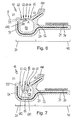
- Fig. 5 is in the profile body 20 of the profile element 10 - as well as in the embodiment of Fig. 2 to 4 -
- a stiffening insert 120 introduced, which extends in the longitudinal direction L of the profile element 10. Transverse to the longitudinal direction L, the reinforcing insert 120 extends from the profile leg 21 of the first section 40 into the Spring leg 54 of the second portion 30 into it.
- Another separate stiffening insert 121 is formed in the support rib 56.
- the stiffening insert 120 extends in the Fig. 5 however, into the closure element 60, which is therefore also reinforced in itself.
- the hinge region 61 which can be adjusted individually due to the reinforcing insert 120 in its elasticity or plasticity.
- the reinforcing insert 120 can ensure that, on the one hand, the resistance during pivoting of the closure element 60 is not too great.
- the reinforcing insert 120 can ensure that the closure element 60 does not return to the functional position A after the rib 82 of the water box cover 80 has been released from the latching recess 50, but remains in the functional position B.
- two closure elements 62, 64 are provided, which centrally close the detent recess 50 in the functional position A.
- a first closure element 62 is formed, while on the opposite second side S2, a second closure element 64 is hinged to the profile body 20.
- a respective hinge region 63, 65 is formed between the closure elements 62, 64 and the spring leg 54 of the profile body 20 on the one hand and the support rib 56 of the profile body 20 on the other hand.
- These are also preferably tapered material regions which enable a pivoting of the respective closure element 62, 64 about an axis parallel to the longitudinal direction L of the profile element 10, so that the closure elements 62, 64 of the in Fig. 6 shown functional position A in an in Fig. 7 shown functional position B can be pivoted.
- the material thickness of the profile body 20 in the hinge areas 63, 65 is chosen such that the closure elements 62, 64 can pivot relatively easily, but still remain stable in itself.
- Both hinge portions 63, 65 are - based on the profile leg 21 of the profile body 20 - approximately at the same height.
- a latching region 68 is formed so that the closure elements 62, 64 in the first functional position A non-positively and / or positively engage each other.
- the latching region 68 may be formed by a latching groove 681, which is formed in the longitudinal direction L of the profile element 10 in the lateral edge of one of the closure elements 62, 64.
- the respective other closure element 62, 64 engages in the functional position A with its lateral edge 682 in the latching groove 681, so that the engagement opening 52 of the latching recess 50 is initially closed centrally over the entire length of the profile element 10 and the spring leg 54 on the closure elements 62, 64 supported on the support rib 56.
- the closure elements 62, 64 lie in a plane E, so that a force acting on the spring leg 54 is always introduced into the support rib 56 via the closure elements 62, 64.
- closure elements 62, 64 as a support cover the locking recess 50 and the latter is - as long as the closure elements 62, 64 are in the functional position A - reliably protected against the ingress of dirt and dust.
- the closure elements 62, 64 in the functional position A bridge the engagement opening 52 of the latching recess 50, so that it is effectively protected against deformation or damage.
- closure elements 62, 64 may also be formed integrally along the longitudinal axis L, in particular via a tapered region forming a predetermined breaking point, which breaks into the recess 50 when the rib 82 of the water box cover 80 penetrates.
- the closure elements 62, 64 on the hinge portions 63, 65 inwardly and laterally out until the rib 82, preferably with a mushroom-shaped end portion 87 is provided in the cross section, behind the shutter members 62, 64 engages.
- the latter thus form in the functional position B itself locking elements which define the rib 82 in the recess 50.
- the insertion of the rib 82 in the joining direction R1 in the recess 50 with a smaller force is possible than the withdrawal of the rib 82 from the recess 50 in the opposite direction R2. This is due to the fact that the closure elements 62, 64 - as in Fig. 7 shown - are employed in the operating position B at an angle oblique to the direction R2 and thus act for the rib 82 and the end portion 87 as a barb.
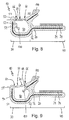
- the profile element 10 according to the invention in the embodiment of Fig. 8 is formed mirrored compared to the previous embodiments.
- the closure element 60 which is once again one-piece, is articulated on the second side S2 via a hinge region 61 to the support rib 56, while the latching region 66 is formed on the opposite side S1 at the free end 55 of the spring leg 54.
- the free edge region 69 of the closure element 60 is provided with a locking groove, while the spring leg end forms a (unspecified) locking projection which engages positively and / or positively in the functional position A in the locking groove.
- the locking element 100 is arranged on the other side in comparison with the previous embodiments, namely on the first side S1. It is attached to a projection 53 which forms an undercut for the detent element 100, so that it can escape when inserting the rib 82 of the water box cover 80 to the rear.
- the profile element of the works Fig. 8 as already described above.
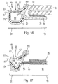
- a further advantageous embodiment is in the Fig. 9 and 10 shown.
- a latching element 70 is provided on the closure element 60, which is designed in the form of a projection which extends in the longitudinal direction L of the profile element 10 and is approximately triangular in cross-section.
- closure element 60 as in Fig. 10 shown, from the first functional position A in the second functional position B, engages the rib 82 of the water box cover 80 with the other nose edge 88 behind the projection 70 on the closure member 60.
- we held the rib 82 not only by the locking element 100 in the recess 50, but also by the locking element 70 of the closure element 60. The latter is also locked in the functional position B, so that the rib 82 is always reliably held in the profile element 10.
- profile element 10 according to the invention shown in the first section 40 is not L-shaped, but U-shaped. It is an extruded profile, which is produced by the coextrusion process, wherein on the underside of the spring leg 54, an insert 26 made of a different material, preferably a stiffer material is provided. This insert 26 serves, for example, to the rigidity of the To optimize spring leg 54.
- the profile body 20 extends in the extrusion direction R, which is also identical here with the longitudinal direction L of the profile element 10. Transversely to the longitudinal direction L, the profile element 10 has a cross section which is adapted to the particular needs of the installation situation, for example, depending on the dimensions and Geometry of the water box cover 80 and / or the windshield 90.
- the U-shaped section 40 of the profile element 10 has in the transition to the second section 30 has a base leg 22 which carries at its ends in each case a profile leg 27, 28. These overlap the edge 92 of an inserted into the U-profile vehicle window 90, which is clamped by the slightly inwardly hired profile legs 27, 28, so that the profile element is held non-positively on the edge 92 of the disc 90 (see Fig. 12 ).
- the base leg 22 carries on its side facing away from the profile legs 27, 28 extending along the longitudinal direction L of the profile element 10 closing element 60 which is integrally formed on the profile body 20 and in the in Fig. 11 Functional position designated A, the locking recess 50 and the engagement opening 52 closes.
- a hinge region 61 is formed on the second side S2 of the latching recess 50. This is, for example - as shown - to a tapered material region, which allows pivoting of the closure element 60 about an axis parallel to the longitudinal direction L of the profile element 10, so that the closure element 60 of the in Fig. 11 shown functional position A in an in Fig. 12 shown functional position B can be pivoted.
- the material thickness of the profile body 20 in the hinge region 61 is selected such that the closure element 60 can pivot relatively easily, but still remains stable in itself.
- a latching area 66 is formed on the spring leg 54, which - based on the profile legs 27, 28 of the profile body 20 - is approximately at the same height as the Hinge area 61.
- the latching area 66 is preferably formed by a latching projection (not specified) which also extends in the longitudinal direction L of the spring leg 54.
- the closure element 60 is a substantially flat element whose plane E in the functional position A is oriented approximately perpendicularly to the base leg 22 of the profile body 20 and to the lower edge 92 of the vehicle window 90, ie the plane E of the closure element 60 and the outer surface 94 of FIG Vehicle window 90 are at least approximately in the edge region of the disc 90 approximately parallel to each other.
- the closure element 60 is hinged on the second side S2 in the hinge region 61 to the base leg 22 of the profile body 20, while the opposite free edge 69 is detachably connected to the spring leg 54.
- closure element 60 As a kind of cover the recess 50 and the latter is - as long as the closure member 60 is in the functional position A - reliably protected from the ingress of dirt and dust.
- closure element 60 bridges the engagement opening 52 of the latching recess 50 in the functional position A, so that the spring leg 54 can be supported with its free end 55 via the closure element 60 on the base leg 22 of the profile body 20.
- the closure element 60 thus forms a kind of support, which gives the profile element 10 in the second section 30 a hollow cross-section which protects the detent recess 50 against deformation and damage.
- the arrangement, design and function of the locking element 100 corresponds to the embodiments already shown, the Fig. 1 to 10 , so that at this point it is fully incorporated by reference.
- Fig. 13 is the locking element 100, which acts as a barb with respect to the rib 82 of the water box cover 80, not disposed within the locking recess 50 and the support rib 56, but first outside the recess 50 on the closure element 60. If the latter - as in Fig. 14 presented - by the Functional position A in the functional position B, then also enters the locking element 100 into the recess 50 and there engages behind - as described above - the rib 82 of the water tank cover 80th
- the closure element 60 can be locked within the latching recess 50 in the second functional position B.
- a latching projection 74 is provided in the latching recess 50, which extends in the longitudinal direction L of the profile element 10.
- a latching groove 75 is formed, which is in the functional position A with the spring leg 54 and in the functional position B with the latching projection 74 in engagement.
- the embodiment of the Fig. 15 shows a variant for the hinge portion 61. This is no longer formed as above by a tapered material area. Rather, the stiffening insert 120 is a piece of free and at this point forms the hinge for the closure element 60, which can pivot over the hinge from the functional position A to the functional position B as described above.
- the closure element 60 is made with respect to the profile body 20 of a different material. But you can also make the closure element 60 and the profile body 20 of the same material and select only for the hinge portion 61 a different material.
- the embodiments of the Fig. 17 and 18 renounce hinge regions 61, 63, 65 between the closure elements 60, 62, 64 and the profile body 20.
- the closure element 60, 62, 64 is rather along the longitudinal direction L of the profile element 10 via tapered formed portions 61 ', 62', 63 ', 65 'connected to the profile body 20.
- the material thickness in these areas 61 ', 62', 63 ', 65' is dimensioned such that the closure element 60 can perform its support function in the functional position A. But that the areas 61 ', 62', 63 ', 65' break up as predetermined breaking points when the rib 82 of the water box cover 80 is introduced into the recess 50 or when the engagement opening 52 is opened by means of a tool.
- closure elements 62, 64 lie deeper in the latching recess 50, namely approximately at the level of the profile leg 21, which thereby derives the forces absorbed by the closure elements 62, 64 in the functional position A.
- the closure element 60 is integrated into the profile 10, wherein the closure element 60 bridges the detent opening on the profile element 10 during bending, mounting on the disk 90 and / or during transport of the disks 90.
- the closure element 60 is either destroyed or it works from the functional position A to the functional position B, so that the rib 82 of the water box cover 80 can be inserted into the locking recess 50 and locked therein. This may possibly even take place in one step together with the installation of the water box 80.
- closure element along the longitudinal direction L of the profile element 10 does not have to be formed completely continuous. Rather, it may also be incised in the manner of a comb or also formed in sections, wherein gaps remain between the individual closure element sections (not shown).
- hinge portions 61, 63, 65 or the predetermined breaking points 61 ', 62', 63 ', 65' may also be formed in sections along the longitudinal direction L of the profile element with gaps (not shown) between them.
- the recess 50 is still well protected against the ingress of dirt.
- the gaps or distances between the closure element sections and / or the hinge sections allow the forces required to open the closure element 60, 62, 64 or the closure elements with the rib 82 of the component 80 to be set even more precisely.
- the profile element 10 is preferably produced as a separate profile strand in an extrusion or coextrusion process. It is also conceivable that the profile element 10 - depending on the cross-sectional geometry - is extruded directly to the edge 92 of the vehicle window 90 or injection-molded in an injection molding.
- a profile element (10) for connecting a component (80) to a vehicle window (90) has a profile body (20) which is connected to a first section (40) on an edge (92) of the vehicle window (90). can be fixed, and in a second portion (30) for releasably securing the component (80) on the profile element (10) has a latching recess (50) which extends in the longitudinal direction (L) of the profile element (10) and in the one Rib (82) of the component (80) non-positively and / or positively lockable.
- the closure element (60, 62, 64) is for this purpose along the longitudinal direction (L) of the profile element (10) on a first side (S1) of the latching recess (50) articulated to the profile body (20).
Claims (20)
- Élément profilé (10) pour la liaison d'un composant (80) avec une vitre de véhicule (90), avec un corps profilé (20), qui peut être fixé avec une première portion (40) au niveau d'un bord (92) de la vitre de véhicule (90) et qui présente, dans une deuxième portion (30), pour la fixation amovible du composant (80) sur l'élément profilé (10), un évidement d'encliquetage (50) avec une ouverture d'emboîtement (52), qui s'étend dans la direction longitudinale (L) de l'élément profilé (10) et dans laquelle une nervure (82) du composant (80) peut être fixé par friction et/ou par complémentarité de forme, caractérisé en ce que, sur le corps profilé (20), se trouve un élément de fermeture (60, 62, 64) qui, dans une première position de fonctionnement (A), ponte l'ouverture d'emboîtement et obture l'évidement d'encliquetage (50).
- Élément profilé selon la revendication 1, caractérisé en ce que l'élément de fermeture (60, 62, 64) est relié le long de la direction longitudinale (L) de l'élément profilé (10) avec le corps profilé (20), plus particulièrement par l'intermédiaire de zones (61', 62', 65') avec rétrécissements, de préférence l'élément de fermeture (60, 62, 64) étant formé d'une seule pièce avec le corps profilé (20) ou est relié par adhérence de matière avec le corps profilé (20).
- Élément profilé selon la revendication 1 ou 2, caractérisé en ce que l'élément de fermeture (60, 62, 64) obture, dans une première position de fonctionnement (A), l'ouverture d'emboîtement (52) de l'évidement d'encliquetage (50) et la libère dans une deuxième position de fonctionnement (B).
- Élément profilé selon l'une des revendications 1 à 3, caractérisé en ce que l'élément de fermeture (60, 62, 64) est un élément plat dont le plan (E) est orienté globalement perpendiculairement au bord (92) de la vitre de véhicule (90).
- Élément profilé selon l'une des revendications 1 à 4, caractérisé en ce que, entre le corps profilé (20) et l'élément de fermeture (60, 62, 64), se trouve une zone de charnière (61, 63, 65).
- Élément profilé selon l'une des revendications 1 à 5, caractérisé en ce que le corps profilé (20) et l'élément de fermeture (60, 62, 64) sont constitués de matériaux différents.
- Élément profilé selon l'une des revendications 1 à 6, caractérisé en ce qu'un élément de fermeture (60) est prévu, qui est articulé, le long de la direction longitudinale (L) de l'élément profilé (10), sur un premier côté (S1) de l'évidement d'encliquetage (50), avec le corps profilé (20).
- Élément profilé selon la revendication 7, caractérisé en ce que l'élément de fermeture (60) est emboîté, le long de la direction longitudinale (L) de l'élément profilé (10), sur le deuxième côté (S2), se trouvant en face du premier côté (S1), de l'évidement d'encliquetage (50), dans la première position de fonctionnement (A), par friction et/ou par complémentarité de forme avec le corps profilé (20).
- Élément profilé selon la revendication 7, caractérisé en ce que l'élément de fermeture (60) est relié, le long de la direction longitudinale (L) de l'élément profilé (10), sur le deuxième côté (S2), opposé au premier côté (S1), de l'évidement d'encliquetage (50), dans la première position de fonctionnement (A), par l'intermédiaire d'une zone à rétrécissement (62'), avec le corps profilé (20).
- Élément profilé selon l'une des revendications 1 à 6, caractérisé en ce que deux éléments de fermeture (62, 64) sont prévus, un premier élément de fermeture (62) étant articulé sur un premier côté (S1) de l'évidement d'encliquetage (50) et un deuxième élément de fermeture (64) étant articulé, sur le deuxième côté (S2), opposé au premier côté (S1), de l'évidement d'encliquetage (50), le long de la direction longitudinale (L) de l'élément profilé (10), avec le corps profilé (20).
- Élément profilé selon la revendication 10, caractérisé en ce que les éléments de fermeture (62, 64), dans la première position de fonctionnement (A), sont emboîtés entre eux par friction et/ou par complémentarité de forme et/ou sont reliés entre eux par l'intermédiaire d'une zone à rétrécissement (63').
- Élément profilé selon l'une des revendications 1 à 11, caractérisé en ce qu'au moins un élément de fermeture (60, 62, 64) peut être bloqué dans la deuxième position de fonctionnement (B), à l'intérieur de l'évidement d'encliquetage (50).
- Élément profilé selon l'une des revendications 1 à 12, caractérisé en ce que l'élément de fermeture (60, 62, 64) est conçu de façon à ce qu'il forme, dans la deuxième position de fonctionnement (B), un élément d'encliquetage pour la nervure (82) du composant (80).
- Élément profilé selon l'une des revendications 1 à 13, caractérisé en ce que l'élément de fermeture (60, 62, 64) comprend ou supporte au moins un élément d'encliquetage (70) qui peut être emboîté, dans la deuxième position de fonctionnement (B), par friction et/ou par complémentarité de forme, avec la nervure (82) du composant (80).
- Élément profilé selon l'une des revendications 1 à 14, caractérisé en ce qu'un élément d'encliquetage (100) est prévu pour la nervure (82) du composant (80) à l'intérieur de l'évidement d'encliquetage (50).
- Élément profilé selon la revendication 13 ou 15, caractérisé en ce que l'élément d'encliquetage (70) de l'élément de fermeture (60, 62, 64) et/ou l'élément d'encliquetage (100) prévu à l'intérieur de l'évidement d'encliquetage (50) constitue un contre-crochet par rapport à la nervure (82) du composant (80).
- Élément profilé selon l'une des revendications 1 à 16, caractérisé en ce que- la première portion (40) de l'élément profilé (10) présente une forme de U ou- la première portion (40) de l'élément profilé (10) présente une forme de L et de préférence la première portion (40) de l'élément profilé (10) comprend un montant profilé (21) qui comporte, au moins sur une partie, une couche adhésive (24).
- Élément profilé selon l'une des revendications 1 à 17, caractérisé en ce que le corps profilé (20) comprend ou supporte une lèvre d'étanchéité (110).
- Élément profilé selon l'une des revendications 1 à 18, caractérisé en ce que, dans le corps profilé (20) et/ou dans l'élément de fermeture (60, 62, 64), est prévu, au moins sur une partie, un insert de rigidification (120).
- Dispositif d'étanchéité pour la transition entre une vitre de véhicule (90) et un composant (80), plus particulièrement pour la partie inférieure d'un pare-brise de véhicule, avec un élément profilé (10) selon l'une des revendications 1 à 19.
Priority Applications (1)
| Application Number | Priority Date | Filing Date | Title |
|---|---|---|---|
| PL12770034T PL2675639T3 (pl) | 2011-12-23 | 2012-09-20 | Profilowy element do łączenia części ze stacjonarną szybą pojazdu |
Applications Claiming Priority (2)
| Application Number | Priority Date | Filing Date | Title |
|---|---|---|---|
| DE102011056955.3A DE102011056955B4 (de) | 2011-12-23 | 2011-12-23 | Profilelement zum Verbinden eines Bauelements mit einer Fahrzeugscheibe |
| PCT/EP2012/068582 WO2013091919A1 (fr) | 2011-12-23 | 2012-09-20 | Élément profilé destiné à relier une pièce structurale à une vitre de véhicule fixe |
Publications (2)
| Publication Number | Publication Date |
|---|---|
| EP2675639A1 EP2675639A1 (fr) | 2013-12-25 |
| EP2675639B1 true EP2675639B1 (fr) | 2016-07-20 |
Family
ID=47008535
Family Applications (1)
| Application Number | Title | Priority Date | Filing Date |
|---|---|---|---|
| EP12770034.2A Active EP2675639B1 (fr) | 2011-12-23 | 2012-09-20 | Joint d'étanchéité pour connecter un élément à une vitre fixe de véhicule |
Country Status (10)
| Country | Link |
|---|---|
| US (2) | US9073421B2 (fr) |
| EP (1) | EP2675639B1 (fr) |
| JP (1) | JP6027135B2 (fr) |
| KR (1) | KR101677821B1 (fr) |
| CN (1) | CN104010853B (fr) |
| DE (1) | DE102011056955B4 (fr) |
| ES (1) | ES2587857T3 (fr) |
| MX (1) | MX2014007520A (fr) |
| PL (1) | PL2675639T3 (fr) |
| WO (1) | WO2013091919A1 (fr) |
Cited By (1)
| Publication number | Priority date | Publication date | Assignee | Title |
|---|---|---|---|---|
| WO2023000050A1 (fr) * | 2021-07-19 | 2023-01-26 | Marcopolo S.A. | Élément de positionnement et/ou de fixation d'un composant pour véhicule, structure de positionnement et/ou de fixation, véhicule et procédé de positionnement et/ou de fixation d'un composant pour véhicule |
Families Citing this family (30)
| Publication number | Priority date | Publication date | Assignee | Title |
|---|---|---|---|---|
| GB2493444B (en) * | 2011-08-01 | 2013-12-11 | Nihon Plast Co Ltd | Structure of mounting cowl-top cover |
| US8628141B1 (en) * | 2012-10-25 | 2014-01-14 | GM Global Technology Operations LLC | Closure restraint system with camming self adjustment |
| DE102013204820A1 (de) * | 2013-03-19 | 2014-09-25 | Elkamet Kunststofftechnik Gmbh | Profilelement zum Verbinden einer Fahrzeugscheibe mit einem Abdeckteil und Profilelementbaugruppe |
| JP6294961B2 (ja) * | 2013-06-26 | 2018-03-14 | サン−ゴバン グラス フランス | 自動車窓ガラスの密閉構造 |
| DE202013103287U1 (de) | 2013-07-23 | 2014-10-28 | Rehau Ag + Co | Abdichtungsprofil zum Anschluss eines Anbauteils an eine Scheibe, sowie Abdichtungsanordnung |
| DE202013103364U1 (de) * | 2013-07-25 | 2014-10-27 | Rehau Ag + Co | Abdichtungsanordnung für ein Kraftfahrzeug |
| DE202013103871U1 (de) * | 2013-08-27 | 2014-11-28 | Rehau Ag + Co | Abdichtungsprofil zum Anschluss eines Anbauteils an eine Scheibe, sowie Abdichtungsanordnung |
| JP5907134B2 (ja) * | 2013-09-05 | 2016-04-20 | トヨタ自動車株式会社 | ウインドシールドガラスとカウルルーバとの連結構造 |
| KR101877146B1 (ko) * | 2013-09-24 | 2018-07-10 | 쌩-고벵 글래스 프랑스 | 차량 창문용 밀폐 배열체 |
| JP2015137051A (ja) * | 2014-01-23 | 2015-07-30 | トヨタ自動車株式会社 | カウルルーバの係止構造 |
| CN104276013B (zh) * | 2014-09-26 | 2016-09-14 | 安徽省地坤汽车天窗科技有限公司 | 一种汽车天窗玻璃的固定装置 |
| US9649913B2 (en) * | 2015-01-21 | 2017-05-16 | Toyota Motor Engineering & Manufacturing North America, Inc. | Cowl louver clip assemblies for cowl louver structures for supporting windshields |
| FR3032680B1 (fr) * | 2015-02-13 | 2017-02-17 | Saint Gobain | Vitrage comprenant un cordon profile de clippage avec trou |
| FR3036330B1 (fr) * | 2015-05-22 | 2018-08-31 | Saint-Gobain Glass France | Vitrage feuillete comprenant un cordon profile de clippage a ruban polymerique supplementaire et cordon profile |
| EP3103665B1 (fr) | 2015-06-09 | 2019-07-24 | Elkamet Kunststofftechnik GmbH | Baguette profilée, système et procédé de fabrication d'une baguette profilée |
| DE102015010073B3 (de) * | 2015-08-03 | 2016-11-17 | Henniges Automotive Gmbh & Co. Kg | Scheibenanordnung, insbesondere Karosserie-Scheibenanordnung |
| CN105387207B (zh) * | 2015-12-14 | 2018-06-26 | 江苏科瑞恩自动化科技有限公司 | 一种玻璃密封条及其密封方式 |
| US10562274B1 (en) | 2016-02-22 | 2020-02-18 | Apple Inc. | Glass fastening and sealing systems |
| DE202016107353U1 (de) * | 2016-12-23 | 2018-03-27 | Rehau Ag + Co | Abdichtungsprofil zum Verbinden eines Anbauteils mit einer Fahrzeugscheibe |
| WO2018123777A1 (fr) * | 2016-12-26 | 2018-07-05 | 旭硝子株式会社 | Verre de fenêtre avec élément d'étanchéité monté sur celui-ci |
| US10118474B2 (en) * | 2017-03-24 | 2018-11-06 | GM Global Technology Operations LLC | Sealing assembly for automotive glass |
| CN108394261A (zh) * | 2018-04-11 | 2018-08-14 | 北京汽车研究总院有限公司 | 一种车门下封条和具有其的车辆 |
| DE102019123996A1 (de) * | 2019-09-06 | 2021-03-11 | Elkamet Kunststofftechnik Gmbh | Verbindungsanordnung |
| DE102019127378A1 (de) * | 2019-10-10 | 2021-04-15 | Elkamet Kunststofftechnik Gmbh | Leistenanordnung und Verfahren zur Herstellung |
| DE102019133589A1 (de) * | 2019-12-09 | 2021-06-10 | Elkamet Kunststofftechnik Gmbh | Verbindungsanordnung |
| DE102020000162B3 (de) * | 2020-01-14 | 2021-02-18 | Elkamet Kunststofftechnik Gmbh | Nutleiste und Verfahren zur Herstellung |
| US20230049818A1 (en) * | 2020-01-20 | 2023-02-16 | Saint-Gobain Glass France | Sealing system for connecting drainage device to vehicle window glass |
| DE102020123593A1 (de) | 2020-09-10 | 2022-03-10 | Elkamet Kunststofftechnik Gmbh | Nutleiste mit Abstandhalter, Montageverfahren und Anordnung umfassend diese Nutleiste |
| CN113043814B (zh) * | 2021-03-24 | 2022-07-05 | 东风商用车有限公司 | 一种后风窗加强结构及车辆 |
| DE102021128299A1 (de) | 2021-10-29 | 2023-05-04 | Wacker Neuson Produktion GmbH & Co. KG | Arbeitsmaschine mit einer Abdeckeinheit zum Abdecken oder Öffnen einer Öffnung |
Family Cites Families (15)
| Publication number | Priority date | Publication date | Assignee | Title |
|---|---|---|---|---|
| FR2600017A1 (fr) * | 1986-06-12 | 1987-12-18 | Profil | Entourage de vitre collee et notamment de vitre fixe de vehicule automobile |
| JPH0544646U (ja) * | 1991-11-21 | 1993-06-15 | 三菱自動車工業株式会社 | 自動車のウインドウのランチヤンネル構造 |
| DE19961706B4 (de) | 1999-12-21 | 2004-09-09 | Saint-Gobain Sekurit Deutschland Gmbh & Co. Kg | Verbindung einer Fahrzeugscheibe mit einem angrenzenden Bauteil |
| DE20008555U1 (de) * | 2000-05-12 | 2000-08-17 | Elkamet Kunststofftechnik Gmbh | Abdichtungs-Anordnung für Fahrzeugscheiben |
| FR2867144B1 (fr) * | 2004-03-03 | 2007-09-21 | Peugeot Citroen Automobiles Sa | Dispositif de fixation d'un element de carrosserie de vehicule automobile |
| BRPI0512835A (pt) * | 2004-07-02 | 2008-04-08 | Kunststoff Technik Scherer & T | tira de vedação de borda de plástico e cabeçote de encaixe |
| FR2885847B1 (fr) * | 2005-05-19 | 2007-08-17 | Peugeot Citroen Automobiles Sa | Dispositif d'etancheite entre un pare-brise et une grille d'auvent d'un vehicule automobile et vehicule automobile comportant un tel dispositif d'etancheite |
| DE102006038013B4 (de) | 2006-08-14 | 2015-05-28 | Richard Fritz Gmbh + Co. Kg | Verfahren zum Verbinden eines Grundkörpers mit einem Bauteil und Vorrichtung zum Durchführen des Verfahrens |
| DE102008003252A1 (de) | 2008-01-04 | 2009-07-16 | Rehau Ag + Co | Scheibenanordnung |
| DE202008006986U1 (de) * | 2008-05-23 | 2009-10-01 | Elkamet Kunststofftechnik Gmbh | Profilelement zum Verbinden einer Fahrzeugscheibe mit einem Wasserkasten |
| DE102008050130B4 (de) * | 2008-10-04 | 2015-09-24 | Henniges Automotive Gmbh & Co. Kg | Automobil-Glasscheibe |
| DE202008016217U1 (de) * | 2008-12-09 | 2009-04-02 | Elkamet Kunststofftechnik Gmbh | Profilelement |
| DE102009010015A1 (de) * | 2009-02-21 | 2010-08-26 | Henniges Automotive Gmbh & Co. Kg | Autoglasscheibe mit auf den Rand aufgeklebtem Leistenteil |
| FR2945521B1 (fr) | 2009-05-15 | 2011-05-13 | Rehau Sa | Cle de transport a extraction aisee pour profiles creux ou pieces creuses deformables |
| US7870958B1 (en) | 2010-01-06 | 2011-01-18 | Creative Extruded Products, Inc. | Shipping insert for protecting a motor vehicle window panel and attached molding during shipping and handling |
-
2011
- 2011-12-23 DE DE102011056955.3A patent/DE102011056955B4/de active Active
-
2012
- 2012-09-20 WO PCT/EP2012/068582 patent/WO2013091919A1/fr active Application Filing
- 2012-09-20 JP JP2014547775A patent/JP6027135B2/ja active Active
- 2012-09-20 PL PL12770034T patent/PL2675639T3/pl unknown
- 2012-09-20 US US14/363,319 patent/US9073421B2/en active Active
- 2012-09-20 EP EP12770034.2A patent/EP2675639B1/fr active Active
- 2012-09-20 ES ES12770034.2T patent/ES2587857T3/es active Active
- 2012-09-20 MX MX2014007520A patent/MX2014007520A/es active IP Right Grant
- 2012-09-20 KR KR1020147020536A patent/KR101677821B1/ko active IP Right Grant
- 2012-09-20 CN CN201280064071.7A patent/CN104010853B/zh active Active
-
2015
- 2015-05-26 US US14/720,975 patent/US9399393B2/en active Active
Cited By (1)
| Publication number | Priority date | Publication date | Assignee | Title |
|---|---|---|---|---|
| WO2023000050A1 (fr) * | 2021-07-19 | 2023-01-26 | Marcopolo S.A. | Élément de positionnement et/ou de fixation d'un composant pour véhicule, structure de positionnement et/ou de fixation, véhicule et procédé de positionnement et/ou de fixation d'un composant pour véhicule |
Also Published As
| Publication number | Publication date |
|---|---|
| MX2014007520A (es) | 2015-05-07 |
| PL2675639T3 (pl) | 2017-04-28 |
| DE102011056955B4 (de) | 2015-02-12 |
| ES2587857T3 (es) | 2016-10-27 |
| KR101677821B1 (ko) | 2016-11-29 |
| KR20140113979A (ko) | 2014-09-25 |
| US9073421B2 (en) | 2015-07-07 |
| JP6027135B2 (ja) | 2016-11-16 |
| US20140327267A1 (en) | 2014-11-06 |
| CN104010853A (zh) | 2014-08-27 |
| JP2015502291A (ja) | 2015-01-22 |
| EP2675639A1 (fr) | 2013-12-25 |
| CN104010853B (zh) | 2016-08-24 |
| WO2013091919A1 (fr) | 2013-06-27 |
| US20150251528A1 (en) | 2015-09-10 |
| US9399393B2 (en) | 2016-07-26 |
| DE102011056955A1 (de) | 2013-06-27 |
Similar Documents
| Publication | Publication Date | Title |
|---|---|---|
| EP2675639B1 (fr) | Joint d'étanchéité pour connecter un élément à une vitre fixe de véhicule | |
| EP2285612B1 (fr) | Elément de profil destiné à relier une plaque de véhicule à une grille d'auvent | |
| EP2370282B1 (fr) | Élément profilé en u destiné à relier une vitre de véhicule à un collecteur d'eau | |
| EP2834095B1 (fr) | Élément profilé servant à relier une vitre de véhicule à un élément de recouvrement et ensemble élément profilé | |
| EP1370436B1 (fr) | Ensemble joint | |
| EP3103665B1 (fr) | Baguette profilée, système et procédé de fabrication d'une baguette profilée | |
| EP2463133B1 (fr) | Joint d'étanchéité pour un module de vitrage | |
| DE20321549U1 (de) | Dicht-, Trimm- oder Führungsleiste | |
| EP1722064B1 (fr) | Profilé de jonction, notamment profilé de jonction de tableau | |
| EP2492428B3 (fr) | Bande de crépissage ainsi qu'angles de construction dotés d'une bande de crépissage | |
| WO2006097147A1 (fr) | Ensemble d'etancheite | |
| DE60320276T9 (de) | Dichtungs-, zier- oder führungsstreifen | |
| DE102012110472B3 (de) | Montage- und Transportprofil für ein Profilelement | |
| EP2450240B1 (fr) | Baguette de jonction en plusieurs parties | |
| DE3241906A1 (de) | Fahrzeugkarosserie mit zumindest einer daran durch ein haftmittel befestigten zier- oder schutzleiste | |
| DE60311697T2 (de) | Flexible Fensterdichtungsleiste | |
| EP3330471B1 (fr) | Baguette de recouvrement destinée à être appliquée sur un composant ainsi que procédé d'application de ladite baguette de recouvrement sur un composant | |
| DE2738142A1 (de) | U-foermiger profilstreifen | |
| EP3419845B1 (fr) | Ensemble de véhicule automobile, unité de prémontage, baguette profilée et procédé de montage d'un ensemble de véhicule automobile | |
| DE10228615B4 (de) | Dichtelement für ein öffnungsfähiges Fahrzeugdach | |
| WO2009010146A1 (fr) | Dispositif d'étanchéité | |
| DE3609101C2 (de) | Schwellerleiste und Befestigungsvorrichtung dafür | |
| WO1996018018A1 (fr) | Dispositif de fixation | |
| EP3711990B1 (fr) | Élément de liaison avec deux dispositifs de maintien indépendants | |
| EP1422095A2 (fr) | Couvercle de canal de guidage pour fenêtres |
Legal Events
| Date | Code | Title | Description |
|---|---|---|---|
| PUAI | Public reference made under article 153(3) epc to a published international application that has entered the european phase |
Free format text: ORIGINAL CODE: 0009012 |
|
| 17P | Request for examination filed |
Effective date: 20130916 |
|
| AK | Designated contracting states |
Kind code of ref document: A1 Designated state(s): AL AT BE BG CH CY CZ DE DK EE ES FI FR GB GR HR HU IE IS IT LI LT LU LV MC MK MT NL NO PL PT RO RS SE SI SK SM TR |
|
| DAX | Request for extension of the european patent (deleted) | ||
| REG | Reference to a national code |
Ref country code: DE Ref legal event code: R079 Ref document number: 502012007725 Country of ref document: DE Free format text: PREVIOUS MAIN CLASS: B60J0010020000 Ipc: B60J0010000000 |
|
| GRAP | Despatch of communication of intention to grant a patent |
Free format text: ORIGINAL CODE: EPIDOSNIGR1 |
|
| RIC1 | Information provided on ipc code assigned before grant |
Ipc: B60J 10/00 20160101AFI20160211BHEP |
|
| INTG | Intention to grant announced |
Effective date: 20160229 |
|
| GRAS | Grant fee paid |
Free format text: ORIGINAL CODE: EPIDOSNIGR3 |
|
| GRAA | (expected) grant |
Free format text: ORIGINAL CODE: 0009210 |
|
| AK | Designated contracting states |
Kind code of ref document: B1 Designated state(s): AL AT BE BG CH CY CZ DE DK EE ES FI FR GB GR HR HU IE IS IT LI LT LU LV MC MK MT NL NO PL PT RO RS SE SI SK SM TR |
|
| REG | Reference to a national code |
Ref country code: GB Ref legal event code: FG4D Free format text: NOT ENGLISH |
|
| REG | Reference to a national code |
Ref country code: CH Ref legal event code: EP |
|
| REG | Reference to a national code |
Ref country code: IE Ref legal event code: FG4D Free format text: LANGUAGE OF EP DOCUMENT: GERMAN |
|
| REG | Reference to a national code |
Ref country code: AT Ref legal event code: REF Ref document number: 813764 Country of ref document: AT Kind code of ref document: T Effective date: 20160815 |
|
| REG | Reference to a national code |
Ref country code: DE Ref legal event code: R096 Ref document number: 502012007725 Country of ref document: DE |
|
| REG | Reference to a national code |
Ref country code: FR Ref legal event code: PLFP Year of fee payment: 5 |
|
| REG | Reference to a national code |
Ref country code: ES Ref legal event code: FG2A Ref document number: 2587857 Country of ref document: ES Kind code of ref document: T3 Effective date: 20161027 |
|
| REG | Reference to a national code |
Ref country code: LT Ref legal event code: MG4D |
|
| REG | Reference to a national code |
Ref country code: NL Ref legal event code: MP Effective date: 20160720 |
|
| PG25 | Lapsed in a contracting state [announced via postgrant information from national office to epo] |
Ref country code: RS Free format text: LAPSE BECAUSE OF FAILURE TO SUBMIT A TRANSLATION OF THE DESCRIPTION OR TO PAY THE FEE WITHIN THE PRESCRIBED TIME-LIMIT Effective date: 20160720 Ref country code: IS Free format text: LAPSE BECAUSE OF FAILURE TO SUBMIT A TRANSLATION OF THE DESCRIPTION OR TO PAY THE FEE WITHIN THE PRESCRIBED TIME-LIMIT Effective date: 20161120 Ref country code: LT Free format text: LAPSE BECAUSE OF FAILURE TO SUBMIT A TRANSLATION OF THE DESCRIPTION OR TO PAY THE FEE WITHIN THE PRESCRIBED TIME-LIMIT Effective date: 20160720 Ref country code: NL Free format text: LAPSE BECAUSE OF FAILURE TO SUBMIT A TRANSLATION OF THE DESCRIPTION OR TO PAY THE FEE WITHIN THE PRESCRIBED TIME-LIMIT Effective date: 20160720 Ref country code: FI Free format text: LAPSE BECAUSE OF FAILURE TO SUBMIT A TRANSLATION OF THE DESCRIPTION OR TO PAY THE FEE WITHIN THE PRESCRIBED TIME-LIMIT Effective date: 20160720 Ref country code: HR Free format text: LAPSE BECAUSE OF FAILURE TO SUBMIT A TRANSLATION OF THE DESCRIPTION OR TO PAY THE FEE WITHIN THE PRESCRIBED TIME-LIMIT Effective date: 20160720 Ref country code: NO Free format text: LAPSE BECAUSE OF FAILURE TO SUBMIT A TRANSLATION OF THE DESCRIPTION OR TO PAY THE FEE WITHIN THE PRESCRIBED TIME-LIMIT Effective date: 20161020 |
|
| REG | Reference to a national code |
Ref country code: SK Ref legal event code: T3 Ref document number: E 22298 Country of ref document: SK |
|
| PG25 | Lapsed in a contracting state [announced via postgrant information from national office to epo] |
Ref country code: LV Free format text: LAPSE BECAUSE OF FAILURE TO SUBMIT A TRANSLATION OF THE DESCRIPTION OR TO PAY THE FEE WITHIN THE PRESCRIBED TIME-LIMIT Effective date: 20160720 Ref country code: PT Free format text: LAPSE BECAUSE OF FAILURE TO SUBMIT A TRANSLATION OF THE DESCRIPTION OR TO PAY THE FEE WITHIN THE PRESCRIBED TIME-LIMIT Effective date: 20161121 Ref country code: SE Free format text: LAPSE BECAUSE OF FAILURE TO SUBMIT A TRANSLATION OF THE DESCRIPTION OR TO PAY THE FEE WITHIN THE PRESCRIBED TIME-LIMIT Effective date: 20160720 Ref country code: GR Free format text: LAPSE BECAUSE OF FAILURE TO SUBMIT A TRANSLATION OF THE DESCRIPTION OR TO PAY THE FEE WITHIN THE PRESCRIBED TIME-LIMIT Effective date: 20161021 |
|
| REG | Reference to a national code |
Ref country code: DE Ref legal event code: R097 Ref document number: 502012007725 Country of ref document: DE |
|
| PG25 | Lapsed in a contracting state [announced via postgrant information from national office to epo] |
Ref country code: RO Free format text: LAPSE BECAUSE OF FAILURE TO SUBMIT A TRANSLATION OF THE DESCRIPTION OR TO PAY THE FEE WITHIN THE PRESCRIBED TIME-LIMIT Effective date: 20160720 Ref country code: MC Free format text: LAPSE BECAUSE OF FAILURE TO SUBMIT A TRANSLATION OF THE DESCRIPTION OR TO PAY THE FEE WITHIN THE PRESCRIBED TIME-LIMIT Effective date: 20160720 Ref country code: EE Free format text: LAPSE BECAUSE OF FAILURE TO SUBMIT A TRANSLATION OF THE DESCRIPTION OR TO PAY THE FEE WITHIN THE PRESCRIBED TIME-LIMIT Effective date: 20160720 |
|
| REG | Reference to a national code |
Ref country code: CH Ref legal event code: PL |
|
| PLBE | No opposition filed within time limit |
Free format text: ORIGINAL CODE: 0009261 |
|
| STAA | Information on the status of an ep patent application or granted ep patent |
Free format text: STATUS: NO OPPOSITION FILED WITHIN TIME LIMIT |
|
| PG25 | Lapsed in a contracting state [announced via postgrant information from national office to epo] |
Ref country code: BG Free format text: LAPSE BECAUSE OF FAILURE TO SUBMIT A TRANSLATION OF THE DESCRIPTION OR TO PAY THE FEE WITHIN THE PRESCRIBED TIME-LIMIT Effective date: 20161020 Ref country code: DK Free format text: LAPSE BECAUSE OF FAILURE TO SUBMIT A TRANSLATION OF THE DESCRIPTION OR TO PAY THE FEE WITHIN THE PRESCRIBED TIME-LIMIT Effective date: 20160720 Ref country code: SM Free format text: LAPSE BECAUSE OF FAILURE TO SUBMIT A TRANSLATION OF THE DESCRIPTION OR TO PAY THE FEE WITHIN THE PRESCRIBED TIME-LIMIT Effective date: 20160720 |
|
| 26N | No opposition filed |
Effective date: 20170421 |
|
| REG | Reference to a national code |
Ref country code: IE Ref legal event code: MM4A |
|
| PG25 | Lapsed in a contracting state [announced via postgrant information from national office to epo] |
Ref country code: CH Free format text: LAPSE BECAUSE OF NON-PAYMENT OF DUE FEES Effective date: 20160930 Ref country code: IE Free format text: LAPSE BECAUSE OF NON-PAYMENT OF DUE FEES Effective date: 20160920 Ref country code: LI Free format text: LAPSE BECAUSE OF NON-PAYMENT OF DUE FEES Effective date: 20160930 |
|
| PG25 | Lapsed in a contracting state [announced via postgrant information from national office to epo] |
Ref country code: SI Free format text: LAPSE BECAUSE OF FAILURE TO SUBMIT A TRANSLATION OF THE DESCRIPTION OR TO PAY THE FEE WITHIN THE PRESCRIBED TIME-LIMIT Effective date: 20160720 Ref country code: LU Free format text: LAPSE BECAUSE OF NON-PAYMENT OF DUE FEES Effective date: 20160920 |
|
| REG | Reference to a national code |
Ref country code: FR Ref legal event code: PLFP Year of fee payment: 6 |
|
| PG25 | Lapsed in a contracting state [announced via postgrant information from national office to epo] |
Ref country code: HU Free format text: LAPSE BECAUSE OF FAILURE TO SUBMIT A TRANSLATION OF THE DESCRIPTION OR TO PAY THE FEE WITHIN THE PRESCRIBED TIME-LIMIT; INVALID AB INITIO Effective date: 20120920 Ref country code: CY Free format text: LAPSE BECAUSE OF FAILURE TO SUBMIT A TRANSLATION OF THE DESCRIPTION OR TO PAY THE FEE WITHIN THE PRESCRIBED TIME-LIMIT Effective date: 20160720 |
|
| PG25 | Lapsed in a contracting state [announced via postgrant information from national office to epo] |
Ref country code: MK Free format text: LAPSE BECAUSE OF FAILURE TO SUBMIT A TRANSLATION OF THE DESCRIPTION OR TO PAY THE FEE WITHIN THE PRESCRIBED TIME-LIMIT Effective date: 20160720 Ref country code: MT Free format text: LAPSE BECAUSE OF FAILURE TO SUBMIT A TRANSLATION OF THE DESCRIPTION OR TO PAY THE FEE WITHIN THE PRESCRIBED TIME-LIMIT Effective date: 20160720 |
|
| REG | Reference to a national code |
Ref country code: FR Ref legal event code: PLFP Year of fee payment: 7 |
|
| PG25 | Lapsed in a contracting state [announced via postgrant information from national office to epo] |
Ref country code: AL Free format text: LAPSE BECAUSE OF FAILURE TO SUBMIT A TRANSLATION OF THE DESCRIPTION OR TO PAY THE FEE WITHIN THE PRESCRIBED TIME-LIMIT Effective date: 20160720 |
|
| REG | Reference to a national code |
Ref country code: AT Ref legal event code: MM01 Ref document number: 813764 Country of ref document: AT Kind code of ref document: T Effective date: 20170920 |
|
| PG25 | Lapsed in a contracting state [announced via postgrant information from national office to epo] |
Ref country code: AT Free format text: LAPSE BECAUSE OF NON-PAYMENT OF DUE FEES Effective date: 20170920 |
|
| P01 | Opt-out of the competence of the unified patent court (upc) registered |
Effective date: 20230515 |
|
| PGFP | Annual fee paid to national office [announced via postgrant information from national office to epo] |
Ref country code: TR Payment date: 20230912 Year of fee payment: 12 Ref country code: GB Payment date: 20230919 Year of fee payment: 12 Ref country code: CZ Payment date: 20230825 Year of fee payment: 12 |
|
| PGFP | Annual fee paid to national office [announced via postgrant information from national office to epo] |
Ref country code: SK Payment date: 20230825 Year of fee payment: 12 Ref country code: PL Payment date: 20230824 Year of fee payment: 12 Ref country code: FR Payment date: 20230918 Year of fee payment: 12 Ref country code: BE Payment date: 20230918 Year of fee payment: 12 |
|
| PGFP | Annual fee paid to national office [announced via postgrant information from national office to epo] |
Ref country code: ES Payment date: 20231019 Year of fee payment: 12 |
|
| PGFP | Annual fee paid to national office [announced via postgrant information from national office to epo] |
Ref country code: IT Payment date: 20230929 Year of fee payment: 12 Ref country code: DE Payment date: 20231117 Year of fee payment: 12 |