EP1369963B1 - Ein Steckverbinder und ein Verfahren, um einen Anschlusskontakt darin einzupressen - Google Patents
Ein Steckverbinder und ein Verfahren, um einen Anschlusskontakt darin einzupressen Download PDFInfo
- Publication number
- EP1369963B1 EP1369963B1 EP02019456A EP02019456A EP1369963B1 EP 1369963 B1 EP1369963 B1 EP 1369963B1 EP 02019456 A EP02019456 A EP 02019456A EP 02019456 A EP02019456 A EP 02019456A EP 1369963 B1 EP1369963 B1 EP 1369963B1
- Authority
- EP
- European Patent Office
- Prior art keywords
- terminal fitting
- cavity
- stabilizer
- preventing
- angle
- Prior art date
- Legal status (The legal status is an assumption and is not a legal conclusion. Google has not performed a legal analysis and makes no representation as to the accuracy of the status listed.)
- Expired - Lifetime
Links
Images


Classifications
-
- H—ELECTRICITY
- H01—ELECTRIC ELEMENTS
- H01R—ELECTRICALLY-CONDUCTIVE CONNECTIONS; STRUCTURAL ASSOCIATIONS OF A PLURALITY OF MUTUALLY-INSULATED ELECTRICAL CONNECTING ELEMENTS; COUPLING DEVICES; CURRENT COLLECTORS
- H01R13/00—Details of coupling devices of the kinds covered by groups H01R12/70 or H01R24/00 - H01R33/00
- H01R13/02—Contact members
- H01R13/10—Sockets for co-operation with pins or blades
- H01R13/11—Resilient sockets
- H01R13/113—Resilient sockets co-operating with pins or blades having a rectangular transverse section
-
- H—ELECTRICITY
- H01—ELECTRIC ELEMENTS
- H01R—ELECTRICALLY-CONDUCTIVE CONNECTIONS; STRUCTURAL ASSOCIATIONS OF A PLURALITY OF MUTUALLY-INSULATED ELECTRICAL CONNECTING ELEMENTS; COUPLING DEVICES; CURRENT COLLECTORS
- H01R13/00—Details of coupling devices of the kinds covered by groups H01R12/70 or H01R24/00 - H01R33/00
- H01R13/40—Securing contact members in or to a base or case; Insulating of contact members
- H01R13/42—Securing in a demountable manner
- H01R13/422—Securing in resilient one-piece base or case, e.g. by friction; One-piece base or case formed with resilient locking means
- H01R13/4223—Securing in resilient one-piece base or case, e.g. by friction; One-piece base or case formed with resilient locking means comprising integral flexible contact retaining fingers
-
- H—ELECTRICITY
- H01—ELECTRIC ELEMENTS
- H01R—ELECTRICALLY-CONDUCTIVE CONNECTIONS; STRUCTURAL ASSOCIATIONS OF A PLURALITY OF MUTUALLY-INSULATED ELECTRICAL CONNECTING ELEMENTS; COUPLING DEVICES; CURRENT COLLECTORS
- H01R13/00—Details of coupling devices of the kinds covered by groups H01R12/70 or H01R24/00 - H01R33/00
- H01R13/64—Means for preventing incorrect coupling
- H01R13/642—Means for preventing incorrect coupling by position or shape of contact members
-
- H—ELECTRICITY
- H01—ELECTRIC ELEMENTS
- H01R—ELECTRICALLY-CONDUCTIVE CONNECTIONS; STRUCTURAL ASSOCIATIONS OF A PLURALITY OF MUTUALLY-INSULATED ELECTRICAL CONNECTING ELEMENTS; COUPLING DEVICES; CURRENT COLLECTORS
- H01R43/00—Apparatus or processes specially adapted for manufacturing, assembling, maintaining, or repairing of line connectors or current collectors or for joining electric conductors
- H01R43/16—Apparatus or processes specially adapted for manufacturing, assembling, maintaining, or repairing of line connectors or current collectors or for joining electric conductors for manufacturing contact members, e.g. by punching and by bending
-
- H—ELECTRICITY
- H01—ELECTRIC ELEMENTS
- H01R—ELECTRICALLY-CONDUCTIVE CONNECTIONS; STRUCTURAL ASSOCIATIONS OF A PLURALITY OF MUTUALLY-INSULATED ELECTRICAL CONNECTING ELEMENTS; COUPLING DEVICES; CURRENT COLLECTORS
- H01R13/00—Details of coupling devices of the kinds covered by groups H01R12/70 or H01R24/00 - H01R33/00
- H01R13/02—Contact members
- H01R13/10—Sockets for co-operation with pins or blades
- H01R13/11—Resilient sockets
- H01R13/111—Resilient sockets co-operating with pins having a circular transverse section
Definitions
- the present invention relates to a connector and to a method for at least partly inserting a terminal fitting into a cavity..
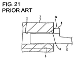
- Terminal fittings provided with stabilizers for stabilizing the insertion of the terminal fittings into cavities of a connector housing have been conventionally known. Specifically, a stabilizer-inserting groove having an open rear end is provided at one lateral edge of an inner surface of the cavity, and the stabilizer projecting from the terminal fitting inserted into the cavity from behind is inserted into this stabilizer-inserting groove.
- a slanted guide surface is generally formed at the peripheral edge of the rear end of the cavity to guide the terminal fitting into the cavity.
- a stabilizer 4 is not aligned with a stabilizer-inserting groove 5 and comes into abutment against a rear end surface 1a of a connector housing 1, thereby hindering an inserting operation.
- a slanted guide surface 6 is formed at the peripheral edge of the rear end of the cavity 2 as described above, the stabilizer 4 is likely to be guided into the cavity 2 by the inclination of this surface 6. Therefore, there has been a possibility that the terminal fitting 3 may be inserted in an improper posture while biting the ceiling wall of the cavity 2.
- the present invention was developed in view of the above problem and an object thereof is prevent a terminal fitting from being inserted in an improper posture.
- a connector in which at least one terminal fitting is at least partly insertable into a respective cavity provided in a connector housing in an inserting direction, a slanted guide surface for guiding the terminal fitting into the cavity is formed at least partly at the peripheral edge portion of the inserting side end of the cavity by being slanted at an angle to the inserting direction of the terminal fitting, and a stabilizer-inserting groove into which a stabilizer projecting from the terminal fitting is at least partly insertable is so formed in an inner surface of the cavity as to have an open end toward the inserting side, wherein a preventing portion or surface against which the stabilizer can come substantially into abutment when the terminal fitting is inserted In an improper posture is provided at the peripheral edge portion of the inserting side end of the cavity and an angle of the preventing portion or surface to the inserting direction is set smaller than the angle of the slanted guide surface thereto.
- the slanted guide surface is formed at the peripheral edge of the inserting side end of the cavity, except for an edge
- the stabilizer is at least partly inserted into the stabilizer-inserting groove.
- the terminal fitting can be smoothly inserted into the cavity.
- the stabilizer comes into abutment against the preventing portion or surface, thereby preventing the insertion of the terminal fitting.
- the angle of the preventing portion or surface to the inserting direction is set smaller than the angle of the slanted guide surface thereto, the stabilizer is more unlikely to be guided into the cavity.
- the insertion of the terminal fitting in an improper posture can be prevented.
- the slanted guide surface is slanted at an obtuse angle to the inserting direction of the terminal fitting.
- a connector in which a terminal fitting is insertable into a cavity provided in a connector housing from behind, a slanted guide surface for guiding the terminal fitting into the cavity is formed at the peripheral edge of the rear end of the cavity by being slanted at an obtuse angle to an inserting direction of the terminal fitting, and a stabilizer-inserting groove into which a stabilizer projecting from the terminal fitting is insertable is so formed in an inner surface of the cavity as to have an open rear end, wherein a preventing surface against which the stabilizer can come into abutment when the terminal fitting is inserted in an improper posture is provided at the peripheral edge of the rear end of the cavity and an angle of the preventing surface to the inserting direction is set smaller than an angle of the slanted guide surface thereto.
- the preventing portion is arranged point-symmetrical (or symmetrical to the stabilizer-inserting groove with respect to an insertion axis of the terminal fitting into the respective cavity) with respect to the stabilizer-inserting groove.
- the angle of the preventing portion is about 90° with respect to the inserting direction, so that the stabilizer can comesubstantially into surface contact with the preventing portion and/or an inserting side end surface of the connector housing.
- the preventing portion and an inserting side end surface of the connector housing are substantially continuous and in flush with each other.
- the preventing portion is arranged such that it comes into contact with the stabilizer in such a way as to avoid a contact of a locking projection of the terminal fitting with the connector housing in case the terminal fitting is improperly oriented while being inserted.
- the preventing surface is recessed with respect to an inserting side surface of the connector housing.
- a method for at least partly inserting at least one terminal fitting into a respective cavity provided in a connector housing of a connector comprising the steps of:
- the guiding is done by means of a slanted guide surface which is formed at the peripheral edge of the inserting side end of the cavity, except for an edge portion of the inserting side end of the cavity where the preventing surface is formed.
- the terminal fitting is guided by means of the slanted guide surface being slanted at an obtuse angle to the inserting direction of the terminal fitting.
- the preventing portion is arranged point-symmetrical with respect to the stabilizer-inserting groove.
- the stabilizer comes substantially into contact with the preventing portion in such a way as to avoid a contact of a locking projection of the terminal fitting with the connector housing.
- FIGS. 1 to 18 A first preferred embodiment of the present invention is described with reference to FIGS. 1 to 18.
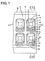
- a female connector in which one or more female terminal fittings 30 are at least partly inserted or insertable in a female connector housing 10 (hereinafter, merely “female housing 10"). While being at least partly accommodated in the female housing 10, the female terminal fittings 30 are electrically connectable with male terminal fittings accommodated in a mating male housing (neither male terminal fittings nor male housing is shown) to be connected with the female housing 10.
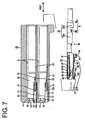
- directions of inserting and withdrawing the female terminal fittings 30 into and from the female housing 10 are referred to as a forward direction and a backward direction, respectively, and reference is made to FIG. 7 concerning vertical direction.
- the female housing 10 is molded e.g. of a resin by a pair of front and rear molds which are closed and opened substantially along forward and backward or longitudinal directions (inserting and withdrawing directions IWD of the female terminal fittings 30).
- a plurality of cavities 11 into which the female terminal fittings 30 are at least partly insertable in an inserting direction ID, preferably substantially from behind, are arranged substantially side by side along widthwise direction at one or more, e.g. two stages as shown in FIGS. 1 and 7.
- the female terminal fitting 30 inserted into the cavity 11 can be resiliently locked by a lokking portion 13 projecting from a bottom or lateral wall 12 of the cavity 11 and can be supported at its front-limit position by the front wall 14 of the female housing 10.
- the front wall 14 of the female housing 10 is formed with tab insertion holes 15 for permitting tabs of the mating male terminal fittings to be at least partly inserted into the cavities 11 from front, and conical or slanted or converging guide surfaces 16 are formed at the front edges of the tab insertion holes 15 preferably over the substantially entire circumference, so that the insertion of the tabs can be smoothly guided.
- mold-removal holes 17 used to remove the front mold for forming the locking portion 13 at the time of molding the female housing 10 forward are formed.
- each mold-removal hole 17 in the front wall 14 At a widthwise center position of the upper end of each mold-removal hole 17 in the front wall 14, a substantially triangular projecting portion 18 projecting down is formed, and the guide surface 16 is continuously formed at the projecting portion 18, too.
- About 1/4 of a front portion of the bottom wall 12 of each cavity 11 is formed to be lower or projecting downward to form a stepped or lowered portion 12a, and the cantilever-shaped locking portion 13 projects forward from a resulting stepped or lowered portion 12a.
- This locking portion 13 is inclined upward to the front as a whole so as to gradually project upward, i.e.
- the locking portion 13 is retracted into a deformation permitting space defined in a lowered portion 12a of the bottom wall 12.
- a locking projection 52 of the female terminal fitting 30 can enter a space provided before the locking portion 13.
- the lowered portion 12a of the bottom wall 12 substantially facing the locking portion 13 from below prevents an excessive resilient deformation of the locking portion 13 by being brought into engagement with the lower surface of the locking portion 13 at a stage before the locking portion 13 undergoes a resilient deformation beyond its resiliency limit.
- the locking portion 13 is covered by the lowered portion 12a of the bottom wall 12 connected with the front wall 14 over the substantially entire width without being exposed to the cavity 11 located below or to the outside below the female housing 10, thereby being protected.
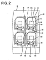
- a projection-inserting groove or recess 19 along which the locking projection 52 and/or a projection 49 of the female terminal fitting 30 are at least partly insertable is formed substantially in the widthwise center of the bottom wall 12, and a stabilizer-inserting groove or recess 20 along which a stabilizer 47 of the female terminal fitting 30 is at least partly insertable and which is deeper than the projection-inserting groove 19 is formed at the right or lateral side of the projection-inserting groove 19 in FIG. 2.
- the projection-inserting groove 19 is formed to be substantially continuous with the locking portion 13 as described below, whereas the front end position of the stabilizer-inserting groove 20 is set at a position slightly behind the locking portion 13.
- the bottom wall 12, the projection-inserting groove 19 and the stabilizer-insertion groove 20 define a stair-like shape in widthwise direction (see FIG. 2).
- a jutting or projecting portion 21 gradually jutting or projecting out inwardly (toward the locking portion 13) over the entire width is provided at the front end of the upper surface (surface substantially facing the locking portion 13) of the cavity 11.
- the front end of the female terminal fitting 30 inserted into the cavity 11 is pushed toward the locking portion 13 by this jutting portion 21 to increase a depth of engagement with the locking portion 13.
- opposite side walls 23 of the cavity 11 bulge out inwardly so that a substantially front half is narrower than a substantially rear half as shown in FIG. 10.
- the construction of the locking portion 13 is described in detail.
- the locking portion 13 is, as shown in FIG. 3, formed such that the lower surface thereof is a slanted surface which is moderately inclined upward to the front preferably over the substantially entire length and the upper surface thereof is a slanted surface similar to the lower surface (slightly steeper than the lower surface) at a rear part 13b of the locking portion 13, but is a substantially horizontal surface (or surface parallel to the inserting and withdrawing directions IWD of the terminal fitting 30) at a front part 13a of the locking portion 13.
- the upper surface of the locking portion 13 is recessed substantially at the widthwise center over the entire length by the projection-inserting groove 19 continuously formed from the rear side of the bottom wall 12.
- the projection-inserting groove 19 is gradually narrowed to the front as a whole and is defined by a bottom surface 19a, a pair of side surfaces 19b extending straight in vertical direction and a pair of slanted surfaces 19c coupling the opposite side surfaces 19b and the bottom surface 19a and inclined inwardly.
- the projection-introducing groove 19 has a constant width preferably over the substantially entire width and is formed by an arcuate surface 19d.
- a widthwise center part of the lower surface of the locking portion 13 is formed into an arcuate surface 13c, which is more moderately curved than the arcuate surface 19d of the projection-introducing groove 19, over the entire length.
- a similar arcuate surface 12b is formed at the lowered portion 12a of the bottom wall 12.
- the width of the locking portion 13 is substantially equal to that of the cavity 11 (slightly smaller than that of the cavity 11) and is constant over the entire length of the locking portion 13.
- the mold-removal hole 17 for the locking portion 13 is formed over such a range wider than the width of the cavity 11 in the front wall 14 of the female housing 10. Accordingly, notches 17a of a specified width are formed in the opposite side walls 23 of the cavity 11 substantially facing the opposite sides of the locking portion 13.
- the thickness of the mold for molding the locking portion 13 can be made larger as much as the widths of the these notches 17a and, thus, a necessary strength can be secured for the mold. Conversely speaking, the width of the locking portion 13 is increased to enhance the strength thereof.
- a pair of maneuverable recesses 24 maneuverable by a jig (not shown) to forcibly resiliently deform the locking portion 13 are formed to be open forward at about 3/5 of the total height of the opposite sides of the front end of the locking portion 13 at the lower parts thereof.
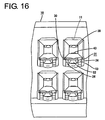
- the maneuverable recesses 24 are so arranged as to be exposed forward to outside even if the female terminal fitting 30 is locked by the lokking portion 13 (see FIG. 16), and can be pressed down or in the deformation direction DD by the jig inserted through the mold-removal hole 17 from front.
- Each maneuverable recess 24 is formed to be substantially triangular when the locking portion 13 is viewed sideways, and the upper surface thereof is substantially horizontal, whereas the lower surface thereof is inclined upward to the back.
- a projecting portion 25 projecting forward is formed over the entire width at about 2/3 of the total height of the front end of the locking portion 13 at the upper part thereof.
- This projecting portion 25 can enter or interact with the locking projection 52 with the locking portion 13 engaged with the female terminal fitting 30.
- the projecting portion 25 has a lower part 25a formed such that its projecting length gradually increases toward the upper end and an upper part 25b (portions above the maneuverable recesses 24) formed to have a constant projecting length.
- the front end surface of the lower part 25a of the projecting portion 25 is a slanted surface inclined upward to the front, whereas that of the upper part 25b is a substantially vertical surface.
- a supporting projection 26 which is fittable into a fittable groove 53 provided in the female terminal fitting 30 to prevent the female terminal fitting 30 from being vertically inclined projects inwardly at a corner portion of the front end position of the cavity 11.
- This supporting projection 26 is substantially block-shaped and has its strength enhanced by being coupled to the front wall 14 (front surface of the cavity 11) of the female housing 10 and the left side wall 23 (inner right surface of the cavity 11 in FIG. 2) of the cavity 11 in FIG. 2.
- This supporting projection 26 is provided at such a position displaced upward or inwardly of the cavity 11 (deforming direction DD of the locking portion 13) with respect to the locking portion 13 that the lower surface thereof faces the mold-removal hole 17.
- the female terminal fitting 30 is formed into a desired shape by, for example, embossing, folding and/or bending a metallic material stamped or cut out into a specified (predetermined or predeterminable) shape.
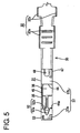
- This female terminal fitting 30 is, as shown in FIGS. 5 and 7, roughly constructed such that a main portion 31 substantially in the form of a box having open front and rear ends and a barrel portion 32 to be crimped or bent or folded into connection with an end of a wire W are connected one after the other.
- the barrel portion 32 is comprised of two front and rear pairs of crimping pieces 32a, 32b, wherein the front pair of crimping pieces 32a are crimped into connection with a core Wa of the wire W, and the rear pair of crimping pieces 32b are crimped or bent or folded into connection with an insulated portion Wb of the wire W.
- the main portion 31 is comprised of a ceiling wall 33 substantially extending in forward and backward or longitudinal directions, a pair of side walls 34, 35 extending down from the opposite lateral edges of the ceiling wall 33, a bottom wall 36 projecting from the projecting end of the left side wall 34 of FIG. 4 to face the ceiling wall 33, and an outer wall 37 projecting from the projecting end of the right side wall 34 of FIG. 4 to be at least partly placed below or outside of the bottom wall 36.
- the front end of the ceiling wall 33 is located at a position retracted backward as compared to those of the other walls 34, 35, 36 and 37, and a resilient contact piece 38 projects from this front end as shown in FIG 7.
- the resilient contact piece 38 is formed to substantially face the ceiling wall 33 and the bottom wall 36, to be supported only at one end and to have a substantially triangular shape as a whole by folding a tongue piece projecting forward from the front end of the ceiling wall 33.
- the resilient contact piece 38 is such that a forward-inclined portion and a backward-inclined portion are provided one after the other behind a substantially U-shaped folded or front portion, and an area extending from the forward-inclined portion over to the backward-inclined portion is embossed to project toward the bottom wall 36, thereby forming a bulging portion 39 preferably substantially in the form of an ellipse narrow in forward and backward or longitudinal directions.
- the peak of this bulging portion 39 serves as a contact portion 40 which can be brought into contact with the tab of the mating male terminal fitting.
- the resilient contact piece 38 is resiliently deformable to approach the ceiling wall 33 with the folded portion as a supporting point of the resilient deformation.
- the bottom end of the resilient contact piece 38 can be brought into contact with the inner surface of the ceiling wall 33, where a recess 41 for enlarging a degree of resilient deformation of the resilient contact piece 38 and preventing the deformed resilient contact piece 38 from a widthwise displacement is formed over a specified (predetermined or predeterminable) length.
- the ceiling wall 33 is embossed at a position substantially facing the contact portion 40 to project toward the contact portion 40, thereby forming an excessive deformation preventing projection 42.
- An excessive resilient deformation of the resilient contact piece 38 beyond its resiliency limit can be prevented by the engagement of the resilient contact piece 38 with the excessive deformation preventing projection 42.
- a receiving portion 43 bulges out inwardly (toward the resilient contact piece 38) at a position of the bottom wall 36 facing the bulging portion 39 and the locking projection 52.
- the tab of the male terminal fitting can be held by being squeezed or positioned between the receiving portion 43 and the resilient contact piece 38.
- the outer wall 37 is divided into a front portion 37a and a rear portion 37b by a cut-away portion 44 formed preferably over the substantially entire width substantially at its longitudinal middle portion.
- the lock portion 13 can enter this cut-away portion 44 over its entire length and can be engaged with a front cut end surface 44a of the cut-away portion 44.
- the front cut end surface 44a of the cut-away portion 44 which surface serves as a locking surface engageable with the locking portion 13 is inclined upward to the back over its entire area.
- This cut-away portion 44 has a length slightly shorter than half the length of the outer wall 37 and extends up to the bottom end of the side wall 35 at the upper side in FIG. 5.
- a bulging piece 45 projecting from the projecting end of the bottom wall 36 is brought into contact with the bottom end surface (cut end surface of the cut-away portion 44 at the side) of this side wall 35 to hold the bottom wall 36 substantially horizontally.
- a recess is so formed as to be slightly lower than a rear half portion thereof over an entire area except a contact portion of the bulging piece 45 with the side wall 35, thereby increasing a depth of engagement with the locking portion 13.
- the front portion 37a of the outer wall 37 is slightly shorter than the rear portion 37b in forward and backward or longitudinal directions.
- a rear-portion holding piece 46 bent toward the ceiling wall 33 (inward direction) and the stabilizer 47 bent in an opposite direction (outward direction) are provided one after the other at the projecting end of the rear portion 37b of the outer wall 37.
- the rear-portion holding piece 46 holds the rear portion 37b while preventing the rear portion 37b from making loose forward and backward movements (or movements along the longitudinal direction of the terminal fitting 30) by being fitted into a rear-portion holding groove 48 formed in the side wall 34 shown in FIG. 6.
- the stabilizer 47 can guide the insertion of the female terminal fitting 30 by being inserted along the stabilizer-inserting groove 20 in the cavity 11.
- the front end of the rear-portion holding piece 46 and the front end of the rear portion 37b are substantially aligned with each other, whereas the rear end of the stabilizer 47 and the rear end of the rear portion 37b are substantially aligned with each other.
- a widthwise center portion of the rear end of the rear portion 37b is embossed to project outward, thereby forming a projection 49 having a length substantially equal to that of the stabilizer 47.
- This projection 49 can be brought into contact with the bottom surface of the cavity 11 (upper surface of the projection-inserting groove 19) when the female terminal fitting 30 is inserted into the cavity 11. It should be noted that the stabilizer 47 projects a larger distance than the projection 49.
- a front-portion holding piece 50 bent toward the ceiling wall 33 is provided at the projecting end of the front portion 37a of the outer wall 37.
- the front-portion holding piece 50 holds the front portion 37a while preventing the front portion 37a from making loose forward and backward or longitudinal movements by being fitted into a front-portion holding groove 51 formed in the side wall 34 shown in FIG. 6.
- This front-portion holding piece 50 projects more backward than the front portion 37a of the outer wall 37.
- the cut-away portion 44 extends into the base end of the front-portion holding piece 50, and the cut end surface 44a thereof is inclined upward to the back as already described. A side end of the locking portion 13 is engageable with this cut end surface 44a.
- a substantially widthwise center (precisely speaking, position slightly displaced to the left side of FIG. 4 from the center) of the rear end (front cut end of the cut-away portion 44) of the front portion 37a of the outer wall 37 is embossed to project outward, thereby forming the locking projection 52 engageable with the locking portion 13.
- the locking projection 52 is, as shown in FIGS. 5 and 6, substantially in the form of a pyramid having a vertex at its front end and is open backward.
- the locking projection 52 is such that a pyramid portion 52a formed by three or more slanted surfaces and a substantially rectangular or parallelepipedic tube portion 52b preferably substantially having constant width and height and formed by three or more side surfaces are connected one after the other.
- the pyramid portion 52a of the lokking projection 52 is tapered and preferably has its front end slightly rounded, so that the locking projection 52 can be smoothly inserted along the projection-inserting groove 19 in the process of inserting the female terminal fitting 30 into the cavity 11.
- the rectangular tube portion 52b of the locking projection 52 is formed to overhang backward or to be back-tapered or undercut substantially along the inclination of the front cut end surface 44a of the cut-away portion 44 and projects more backward than the front portion 37a of the outer wall 37.
- This locking projection 52 projects up to the substantially same height as the projection 49, and is at least partly insertable into the projection-inserting groove 19 of the cavity 11 similar to the projection 49.
- the outward-projecting end of the rectangular tube portion 52b of the locking projection 52 is so set as to reach a part of the locking portion 13 located below the projecting portion 25, thus ensuring a sufficient depth of engagement with the locking portion 13.
- the rear end surface or rear end 52 cof the locking projection 52 serving as a locking surface engageable with the locking portion 13 is formed by the front cut end surface 44a of the cut-away portion 44 and is inclined upward to the back.
- the rear end surfaces of the portions of the front portion 37a of the outer wall 37 at the opposite sides of the locking projection 52 are also formed by the front cut end surface 44a of the cut-away portion 44 inclined inwardly or upward to the back and is engageable with the locking portion 13 as shown in FIG. 8.
- the fittable groove 53 is formed to be open forward.
- the supporting projection 26 provided at the front end position of the cavity 11 is engageable with this fittable groove 53 as the female terminal fitting 30 is at least partly inserted into the cavity 11.
- the female terminal fitting 30 is so supported as not to loosely move along vertical direction (direction intersecting with the inserting and withdrawing directions of the female terminal fitting 30, deforming direction of the locking portion 13).
- a slanted or inclined or tapered or converging guide surface or portion 22 for guiding the female terminal fitting 30 into the cavity 11 is formed except a part thereof (left-upper corner in FIG. 2) as shown in FIGS. 2 and 8.
- This slanted guide surface 22 is formed such that an angle ⁇ thereof to an inserting direction ID of the female terminal fitting 30 into the cavity 11 preferably is 90° or larger, i.e. an obtuse angle.
- a preventing surface 27 (as a preferred preventing portion) which can be brought substantially into abutment against or which can interact with the stabilizer 37 when an attempt is made to at least partly insert the female terminal fitting 30 into the cavity 11 while holding the female terminal fitting 30 in an improper posture which is rotationally shifted (preferably inverted or upside down) of its proper posture is formed at a peripheral edge, preferably at the left-upper corner of the peripheral edge, or edge portion of the rear end of the cavity 11 in FIG. 2 preferably where no slanted guide surface 22 is formed.
- this preventing surface 27 preferably replaces the part of the slanted guide surface 22 formed at the peripheral edge or edge portion of the rear end of the cavity 11.
- the preventing surface 27 preferably is a surface substantially continuous with a rear end surface 10a (as a preferred inserting-side surface) of the female housing 10 and further preferably substantially straight along vertical direction, i.e. substantially normal to the inserting direction ID of the female terminal fitting 30 into the cavity 11.
- an angle ⁇ of the preventing surface 27 to the inserting direction ID of the female terminal fitting 30 into the cavity 11 preferably is about 90°. Accordingly, the angle ⁇ of the preventing surface 27 to the inserting direction ID is smaller than the angle ⁇ of the slanted guide surface 22 thereto.
- the preventing surface 27 is point-symmetrical (diagonally positioned) with respect to the stabilizer-inserting groove 20 provided at the right-lower corner of the cavity 11 in FIG. 2. In other words, the preventing surface 27 is arranged at a position substantially symmetrical with respect to an insertion axis A of the terminal fitting 30 into the respective cavity 11.
- the female terminal fitting 30 is inserted into the cavity 11 in the inserting direction ID, preferably substantially from behind, after the barrel portion 32 thereof is crimped or bent or folded into connection with the wire W. At this time, if the female terminal fitting 30 is at least partly inserted into the cavity 11 while being held in a substantially proper posture in which the stabilizer 47 faces down and is substantially aligned with the stabilizer-inserting groove 20 as shown in FIG. 11, the female terminal fitting 30 is guided into the cavity 11 by the slanted guide surface 22.
- the locking projection 52 is first at least partly introduced into the projection-inserting groove 19 and then the projection 49 and the stabilizer 47 are at least partly introduced into the projection-inserting groove 19 and the stabilizer-inserting groove 20, respectively, whereby the female terminal fitting 30 can be smoothly inserted while being prevented from shaking along vertical and transverse directions (i.e. directions at an angle different from 0° or 180°, preferably substantially normal to the inserting direction ID).
- the locking portion 13 is pressed down by the locking projection 52, thereby being resiliently deformed.
- the locking portion 13 is resiliently deformed in the deformation direction DD to a maximum degree when the front part 13a is pressed by the locking projection 52.
- the locking projection 52 can be smoothly inserted along the projection-inserting groove 19 and can smoothly press the locking portion 13 by being formed into a substantially pyramidal shape having a vertex at the front end.
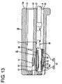
- the locking projection 52 moves beyond the locking portion 13 and the locking portion 13 is resiliently restored to resiliently lock the female terminal fitting 30 while entering the cut-away portion 44 as shown in FIGS. 12 to 15.
- the projecting portion 25 of the locking portion 13 projecting along the inclination of the cut end surface 44a can enter the inside of the locking projection 52. Since the front end of the main portion 31 is so displaced as to approach the locking portion 13 by being pushed down by the jutting portion 21 on the ceiling surface of the cavity 11 in this process, the depth of engagement of the locking portion 13 with the female terminal fitting 30 is increased.
- the locking projection 52 is located at a position displaced from both maneuverable recesses 24 of the locking portion along widthwise direction and is exposed forward to outside via the maneuverable recesses 24 and the mold-removal hole 17 as shown in FIG. 16.
- the front cut end surface 44a of the cut-away portion 44 which is the locking surface engageable with the locking portion 13 is formed to reach the front portion 37a of the outer wall 37 including the locking projection 52 and the front-portion holding piece 50, i.e. formed substantially over the substantially entire width area of the female terminal fitting 30 as shown in FIGS. 12 to 15.
- the female terminal fitting 30 is held with a strong locking force so as not to come out of the cavity 11.
- the front cut end surface 44a of the cut-away portion 44 is inclined upward to the back, the locking force is even stronger.
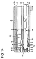
- the female terminal fitting 30 may be held in an improper posture which is rotated from the proper position around the longitudinal direction thereof, e.g. upside down of the proper inserting posture, when being inserted into the cavity 11.
- the locking projection 52 and the stabilizer 47 are facing upward, and the projection-inserting groove 19 and the stabilizer-inserting groove 20 are not aligned with each other.
- the locking projection 52 first comes into abutment against the upper part of the slanted guide surface 22.
- the slanted guide surface 22 is inclined at an obtuse angle to the inserting direction ID, and the locking projection 52 has a substantially pyramidal shape, i.e.
- the locking projection 52 is likely to smash and bite in the upper edge portion of the cavity 11 by an inserting force, thereby permitting the insertion.
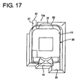
- the front end surface of the stabilizer 47 comes substantially into contact with the rear end surface 10a of the female housing 10 and the preventing surface 27 as shown in FIG. 18, whereby any further insertion is prevented.
- the stabilizer 47 is displaced along widthwise direction (direction substantially normal to the inserting direction ID) from the slanted guide surface 22 (see FIG. 17).
- the preventing surface 27 is preferably arranged at such a position in particular along the inserting direction ID that the locking portion 52 cannot bite into the connector housing 10.
- the stabilizer 47 Since the angle ⁇ of this preventing surface 27 to the inserting direction of the female terminal fitting 30 is set smaller than the angle ⁇ of the slanted guide surface 22 thereto, the stabilizer 47 is more unlikely to be guided into the cavity 11 as compared to prior art connectors provided with no preventing surface (see FIG. 19). Further, since the angle ⁇ of this preventing surface 27 preferably is about 90°, the stabilizer 47 comes or can come substantially into surface contact with the preventing surface 27 and the rear end surface 10a of the female housing 10. Thus, a contact area of the stabilizer 47 is increased by the height H of the preventing surface 27 (slanted guide surface 22) as compared to the prior art connectors and, therefore, the stabilizer 47 is unlikely to bite in the peripheral edge of the cavity 11.
- the insertion of the female terminal fitting 30 in an improper posture can be securely prevented. Since the improper posture of the female terminal fitting 30 can be detected based on an impossibility to insert the female terminal fitting 30, the female terminal fitting 30 is pulled out of the cavity 11 and inserted again after being brought substantially into the proper inserting posture.
- the angle ⁇ of the preventing surface 27, against which the stabilizer 47 comes into abutment when the female terminal fitting 30 is inserted in an improper posture, with respect to the inserting direction of the female terminal fitting 30 is set smaller than the angle ⁇ of the slanted guide surface 22 thereto, the stabilizer 47 is more unlikely to be guided into the cavity 11.
- the insertion of the female terminal fitting 30 in an improper posture can be securely prevented.
- one or more female terminal fittings 30 are at least partly insertable into respective cavities 11 provided in a female housing 10 preferably from behind.
- a slanted guide surface 22 for guiding the female terminal fitting 30 into the cavity 11 is formed at the peripheral edge or edge portion of the rear end of each cavity 11 by being slanted or inclined at an obtuse angle to an inserting direction of the female terminal fitting 30.
- a stabilizer-inserting groove or recess 20 into which a stabilizer 47 projecting from the female terminal fitting 30 is at least partly insertable is so formed in the bottom surface of the cavity 11 as to have an open rear end (opening side end).
- a preventing surface 27 against which the stabilizer 47 can substantially come into abutment (or with which the stabilizer 47 can interact) when the female terminal fitting 30 is inserted in an improper posture e.g. a posture rotated with respect to the proper posture along the longitudinal axis of the terminal fitting 30
- An angle ⁇ of this preventing surface to the inserting direction is set smaller than an angle ⁇ of the slanted guide surface 22 thereto.
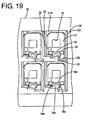
- FIG. 19 A further preferred embodiment of the invention is described with reference to FIG. 19. This embodiment is similar to the previous embodiment except for the shape and proportions of the preventing surface 27A. Accordingly, no repetitive description of those features being similar or same as the previous embodiment is given by denoting them with the same reference numerals.
- the preventing surface 27A of the present embodiment is recessed or stepped inwardly (or in the inserting direction ID) with respect to the rear end or back-end surface 10a (as a preferred inserting-side surface) of the connector housing 10 and thus replaces the guide surface 22 in its region.
- the preventing surface 27A is arranged at an angle to the inserting direction ID of the terminal fitting 30 into the cavity 11 which is smaller than the angle of inclination of the slanted surface 22 and is preferably substantially normal to the inserting direction ID.
- the extension of the preventing surface 27A in a radial direction of the connector housing 10 (or in a direction away from the insertion axis of the terminal fitting into the cavity 11) is substantially the same as that of the guide surface 22.
- the preventing surface 27A is formed by recessing a portion of the guide surface 22 point-symmetrical to the stabilizer-inserting groove 20 to form a step therein.
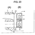
- FIG. 20 A modification of the previous preferred embodiment can be seen in FIG. 20.
- the preventing surface 27A is also stepped or recessed back or inwardly from the back-end surface 10a of the connector housing 10 (as can be seen in FIG. 20(A)).
- the difference to the previous embodiment lies in the fact that the preventing surface 27A projects outward in a radial direction of the connector housing 10 (or in a direction away from the insertion axis A of the terminal fitting into the cavity 11) as compared with the guide surface 22.
- the preventing surface 27A is formed by recessing or cutting out a portion of the guide surface 22 point-symmetrical to the stabilizer-inserting groove 20 and additionally of the rear-end surface 10a of the connector housing 10 to form a step therein.
- the angle ⁇ of this preventing surface 27 to the inserting direction ID of the female terminal fitting 30 is set smaller than the angle ⁇ of the slanted guide surface 22 thereto, so that the stabilizer 47 is more unlikely to be guided into the cavity 11 as compared to prior art connectors provided with no preventing surface.
- the angle ⁇ of this preventing surface 27 to the inserting direction ID of the female terminal fitting 30 preferably is about 90°.
Landscapes
- Engineering & Computer Science (AREA)
- Manufacturing & Machinery (AREA)
- Connector Housings Or Holding Contact Members (AREA)
Claims (11)
- Verbinder bzw. Steckverbinder, in welchem wenigstens ein Anschlußpaßstück bzw. -kontakt (30) wenigstens teilweise in einen entsprechenden Hohlraum (11), welcher in einem Verbindergehäuse (10) vorgesehen ist, in einer Einsetzrichtung (ID) einsetzbar ist, eine geneigte bzw. abgeschrägte Führungsfläche bzw. -oberfläche (22) zum Führen des Anschlußpaßstücks (30) in den Hohlraum (11) wenigstens teilweise an dem Umfangsrand- bzw. -kantenabschnitt des Einsetzseitenendes des Hohlraums (11) ausgebildet ist, indem sie unter einem Winkel (α) zu der Einsetzrichtung (ID) des Anschlußpaßstücks (30) geneigt bzw. abgeschrägt ist, und eine Stabilisiereinrichtungs-Einsetzrille bzw. -nut (20), in welche eine Stabilisiereinrichtung (47), welche von dem Anschlußpaßstück (30) vorragt, wenigstens teilweise einsetzbar ist, so in einer inneren Fläche bzw. Oberfläche des Hohlraums (11) ausgebildet ist, um ein offenes Ende zu der Einsetzseite aufzuweisen, wobei ein verhindernder Abschnitt (27; 27A), gegen welchen die Stabilisiereinrichtung (47) im wesentlichen in Anlage bzw. Anschlag gelangen kann, wenn das Anschlußpaßstück (30) in einer nicht entsprechenden bzw. inkorrekten Lage bzw. nicht ordnungsgemäß eingesetzt ist, an dem Umfangsrandabschnitt des Einsetzseitenendes des Hohlraums (11) vorgesehen ist und ein Winkel (β) des verhindernden Abschnitts (27; 27A) zu der Einsetzrichtung (ID) kleiner als der Winkel (α) der abgeschrägten Führungsfläche (22) dazu eingestellt ist, dadurch gekennzeichnet, daß die abgeschrägte Führungsfläche (22) an dem Umfangsrandabschnitt des Einsetzseitenendes des Hohlraums (11) mit Ausnahme eines Rand- bzw. Kantenabschnitts des Einsetzseitenendes des Hohlraums (11) ausgebildet ist, wo die verhindernde Fläche (27, 27a) ausgebildet ist.
- Verbinder nach Anspruch 1, wobei die abgeschrägte Führungsfläche (22) unter einem stumpfen Winkel (α) zu der Einsetzrichtung (ID) des Anschlußpaßstücks (30) abgeschrägt bzw. geneigt ist.
- Verbinder nach einem oder mehreren der vorangehenden Ansprüche, wobei der verhindernde Abschnitt (27; 27A) punktsymmetrisch in bezug auf die Stabilisiereinrichtungs-Einsetzrille (20) angeordnet ist.
- Verbinder nach einem oder mehreren der vorangehenden Ansprüche, wobei der Winkel (β) des verhindernden Abschnitts (27; 27A) etwa 90° in bezug auf die Einsetzrichtung (ID) beträgt, sodaß die Stabilisiereinrichtung (47) im wesentlichen in Oberflächenkontakt bzw. flächigen Kontakt mit dem verhindernden Abschnitt (27; 27A) und/oder einer Einsetzseitenendfläche bzw. -oberfläche (10a) des Verbindergehäuses (10) gelangen kann.
- Verbinder nach einem oder mehreren der vorangehenden Ansprüche, wobei der verhindernde Abschnitt (27; 27A) und eine Fläche bzw. Oberfläche (10a) des Einsetzseitenendes des Verbindergehäuses (10) im wesentlichen kontinuierlich bzw. anschließend und bündig miteinander sind.
- Verbinder nach einem oder mehreren der vorangehenden Ansprüche, wobei der verhindernde Abschnitt (27; 27A) derart angeordnet ist, daß er in Kontakt mit der Stabilisiereinrichtung (47) in einer derartigen Weise gelangt, um einen Kontakt eines verriegelnden bzw. Verriegelungsvorsprungs (52) des Anschlußpaßstücks (30) mit dem Verbindergehäuse (10) in einem Fall zu vermeiden, daß das Anschlußpaßstück (30) nicht ordnungsgemäß orientiert ist, während es eingesetzt ist bzw. wird.
- Verbinder nach einem oder mehreren der Ansprüche 1-4 oder 6, wobei die verhindernde Oberfläche (27A) in bezug auf eine Fläche bzw. Oberfläche (10a) der Einsetzseite des Verbindergehäuses (10) vertieft bzw. abgesetzt ist.
- Verfahren für ein wenigstens teilweises Einsetzen von wenigstens einem Anschlußpaßstück bzw. -kontakt (30) in einen entsprechenden Hohlraum (11), welcher in einem Verbindergehäuse (10) vorgesehen wird, in einer Einsetzrichtung (ID), umfassend die Schritte eines:wobei eine Stabilisiereinrichtung (47), welche von dem Anschlußpaßstück (30) vorragt, wenigstens teilweise in eine Stabilisiereinrichtungs-Einsetzrille bzw. -nut (20) eingesetzt wird, welche in einer inneren Fläche bzw. Oberfläche des Hohlraums (11) ausgebildet ist, um ein offenes Ende zu der Einsetzseite aufzuweisen, wenn das Anschlußpaßstück (30) im wesentlichen in einer ordnungsgemäßen Lage orientiert wird, während eine nicht ordnungsgemäße Orientierung des Anschlußpaßstücks (30) durch das Zusammenwirken der Stabilisiereinrichtung (47) mit einem verhindernden Abschnitt (27; 27A) detektiert wird, welcher an dem Umfangsrandabschnitt bzw. Kantenabschnitt des Einsetzseitenendes des Hohlraums (11) vorgesehen wird und einen Winkel (β) zu der Einsetzrichtung (ID) aufweist, welcher geringer als der Winkel (α) der abgeschrägten Führungsfläche (22) dazu ist, dadurch gekennzeichnet, daß das Führen mittels einer abgeschrägten Führungsfläche bzw. -oberfläche (22) durchgeführt wird, welche an dem Umfangsrand des Einsetzseitenendes des Hohlraums (11) mit Ausnahme eines Rand- bzw. Kantenabschnitts des Einsetzseitenendes des Hohlraums (11) ausgebildet wird, wo die verhindernde Oberfläche (27, 27a) ausgebildet wird.wenigstens teilweisen Einsetzens von wenigstens einem Anschlußpaßstück (30) in den entsprechenden Hohlraum (11), während das Anschlußpaßstück (30) in den Hohlraum (11) mittels einer geneigten bzw. abgeschrägten Führungsfläche bzw. -oberfläche (22) geführt wird, welche einen Neigungswinkel (α) zu der Einsetzrichtung (ID) des Anschlußpaßstücks (30) aufweist,
- Verfahren nach Anspruch 8, wobei das Anschlußpaßstück (30) mittels der abgeschrägten Führungsfläche (22) geführt wird, welche unter einem stumpfen Winkel (α) zu der Einsetzrichtung (ID) des Anschlußpaßstücks (30) geneigt ist.
- Verfahren nach Anspruch 8 oder 9, wobei der verhindernde Abschnitt (27; 27A) punktsymmetrisch in bezug auf die Stabilisiereinrichtungs-Einsetzrille (20) angeordnet wird.
- Verfahren nach einem oder mehreren der vorangehenden Ansprüche 8 bis 10, wobei, wenn das Anschlußpaßstück (30) nicht ordnungsgemäß orientiert ist, während es eingesetzt wird, die Stabilisiereinrichtung (47) im wesentlichen in Kontakt mit dem verhindernden Abschnitt (27; 27A) in einer derartigen Weise gelangt, um einen Kontakt eines verriegelnden bzw. Verriegelungsvorsprungs (52) des Anschlußpaßstücks (30) mit dem Verbindergehäuse (10) zu vermeiden.
Applications Claiming Priority (4)
| Application Number | Priority Date | Filing Date | Title |
|---|---|---|---|
| JP2002166360A JP3415132B1 (ja) | 2002-06-06 | 2002-06-06 | 端子金具及びコネクタ |
| JP2002166360 | 2002-06-06 | ||
| JP2002218603 | 2002-07-26 | ||
| JP2002218603A JP3415142B1 (ja) | 2002-07-26 | 2002-07-26 | コネクタ |
Publications (2)
| Publication Number | Publication Date |
|---|---|
| EP1369963A1 EP1369963A1 (de) | 2003-12-10 |
| EP1369963B1 true EP1369963B1 (de) | 2005-10-12 |
Family
ID=29552397
Family Applications (1)
| Application Number | Title | Priority Date | Filing Date |
|---|---|---|---|
| EP02019456A Expired - Lifetime EP1369963B1 (de) | 2002-06-06 | 2002-08-30 | Ein Steckverbinder und ein Verfahren, um einen Anschlusskontakt darin einzupressen |
Country Status (4)
| Country | Link |
|---|---|
| US (1) | US6817904B2 (de) |
| EP (1) | EP1369963B1 (de) |
| CN (1) | CN1253972C (de) |
| DE (1) | DE60206604T2 (de) |
Families Citing this family (17)
| Publication number | Priority date | Publication date | Assignee | Title |
|---|---|---|---|---|
| JP4238746B2 (ja) * | 2004-03-09 | 2009-03-18 | 住友電装株式会社 | コネクタ |
| JP4456494B2 (ja) * | 2005-02-02 | 2010-04-28 | 住友電装株式会社 | 端子金具 |
| JP4607749B2 (ja) * | 2005-12-06 | 2011-01-05 | トヨタ自動車株式会社 | 雌型コネクタ端子及び雌型コネクタ |
| WO2007103094A2 (en) * | 2006-03-06 | 2007-09-13 | Yahoo! Inc. | System for serving advertisements over mobile devices |
| JP5050823B2 (ja) * | 2007-12-10 | 2012-10-17 | 住友電装株式会社 | コネクタ |
| JP5233822B2 (ja) * | 2009-04-24 | 2013-07-10 | 住友電装株式会社 | 端子金具 |
| JP5396310B2 (ja) * | 2010-03-01 | 2014-01-22 | 住友電装株式会社 | コネクタ |
| JP5549624B2 (ja) * | 2011-02-28 | 2014-07-16 | 住友電装株式会社 | コネクタ |
| JP5712673B2 (ja) * | 2011-02-28 | 2015-05-07 | 住友電装株式会社 | 端子金具 |
| JP5772468B2 (ja) * | 2011-10-06 | 2015-09-02 | 住友電装株式会社 | コネクタ |
| JP6211563B2 (ja) | 2015-07-31 | 2017-10-11 | 矢崎総業株式会社 | 端子金具 |
| JP6607393B2 (ja) * | 2016-02-11 | 2019-11-20 | 株式会社オートネットワーク技術研究所 | 端子金具 |
| JP2018018703A (ja) | 2016-07-28 | 2018-02-01 | 矢崎総業株式会社 | コネクタ |
| DE102016125764A1 (de) * | 2016-12-28 | 2018-06-28 | Lear Corporation | Zweistückige elektrische clean-body-anschlussbuchse |
| JP6781934B2 (ja) | 2017-04-26 | 2020-11-11 | 住友電装株式会社 | 端子 |
| JP7054452B2 (ja) * | 2018-11-02 | 2022-04-14 | 住友電装株式会社 | コネクタ |
| JP7435329B2 (ja) * | 2020-07-14 | 2024-02-21 | 住友電装株式会社 | 端子金具 |
Family Cites Families (5)
| Publication number | Priority date | Publication date | Assignee | Title |
|---|---|---|---|---|
| JPH0635402Y2 (ja) * | 1989-03-08 | 1994-09-14 | 日本航空電子工業株式会社 | 誤接続防止構造を有するコネクタ |
| US5980328A (en) * | 1996-09-04 | 1999-11-09 | Sumitomo Wiring Systems, Ltd. | Connector for use with substrates |
| EP1024557A1 (de) * | 1999-01-29 | 2000-08-02 | Sumitomo Wiring Systems, Ltd. | Abdichtende Membrane für einen wasserdichten Steckverbinder und ein wasserdichter Steckverbinder |
| JP2001332334A (ja) | 2000-05-24 | 2001-11-30 | Japan Aviation Electronics Industry Ltd | コネクタ |
| US6439934B1 (en) * | 2001-12-14 | 2002-08-27 | Hon Hai Precision Ind. Co., Ltd. | High-speed electrical connector |
-
2002
- 2002-08-30 EP EP02019456A patent/EP1369963B1/de not_active Expired - Lifetime
- 2002-08-30 DE DE60206604T patent/DE60206604T2/de not_active Expired - Lifetime
-
2003
- 2003-01-20 CN CNB031018203A patent/CN1253972C/zh not_active Expired - Lifetime
- 2003-05-20 US US10/441,659 patent/US6817904B2/en not_active Expired - Lifetime
Also Published As
| Publication number | Publication date |
|---|---|
| EP1369963A1 (de) | 2003-12-10 |
| DE60206604D1 (de) | 2006-02-23 |
| CN1467879A (zh) | 2004-01-14 |
| US20030228797A1 (en) | 2003-12-11 |
| CN1253972C (zh) | 2006-04-26 |
| DE60206604T2 (de) | 2006-07-06 |
| US6817904B2 (en) | 2004-11-16 |
Similar Documents
| Publication | Publication Date | Title |
|---|---|---|
| EP1369959B1 (de) | Ein Steckverbinder, ein Entriegelungsorgan und ein Verfahren | |
| EP1369962B1 (de) | Ein Anschlusskontakt und ein beipassender Steckverbinder | |
| EP1369963B1 (de) | Ein Steckverbinder und ein Verfahren, um einen Anschlusskontakt darin einzupressen | |
| US6835097B2 (en) | Connector | |
| US6733346B2 (en) | Terminal fitting, a connector provided therewith and a method for forming a terminal fitting | |
| EP1376768B1 (de) | Ein elektrischer Steckverbinder | |
| US6752660B2 (en) | Terminal fitting, connector provided therewith and method for producing the terminal fitting | |
| EP1369960B1 (de) | Ein Steckverbinder, ein Anschlusskontakt und ein Verfahren, um ein Anschlusskontakt einzupressen | |
| EP1378968B1 (de) | Verbinder | |
| US6948986B2 (en) | Connector | |
| EP1369961B1 (de) | Ein Anschlusskontakt und ein Steckverbinder | |
| US6939171B2 (en) | Connector, molding method therefor and molding apparatus therefor | |
| US6692303B2 (en) | Terminal fitting, a connector and a method for forming a terminal fitting that facilitate insertion of the terminal fitting into the connector | |
| US6953366B2 (en) | Connector | |
| EP1577981B1 (de) | Verbinder und Demontagevorrichtung | |
| JP2004063207A (ja) | コネクタ |
Legal Events
| Date | Code | Title | Description |
|---|---|---|---|
| PUAI | Public reference made under article 153(3) epc to a published international application that has entered the european phase |
Free format text: ORIGINAL CODE: 0009012 |
|
| 17P | Request for examination filed |
Effective date: 20020905 |
|
| AK | Designated contracting states |
Kind code of ref document: A1 Designated state(s): AT BE BG CH CY CZ DE DK EE ES FI FR GB GR IE IT LI LU MC NL PT SE SK TR |
|
| AX | Request for extension of the european patent |
Extension state: AL LT LV MK RO SI |
|
| AKX | Designation fees paid |
Designated state(s): DE FR |
|
| GRAP | Despatch of communication of intention to grant a patent |
Free format text: ORIGINAL CODE: EPIDOSNIGR1 |
|
| RIN1 | Information on inventor provided before grant (corrected) |
Inventor name: NANKOU, YUUICHI Inventor name: KURIMOTO, NAOYA Inventor name: FUKATSU, YUKIHIRO Inventor name: ISHIKAWA, RYOTARO Inventor name: KAWASE, HAJIME |
|
| GRAS | Grant fee paid |
Free format text: ORIGINAL CODE: EPIDOSNIGR3 |
|
| GRAA | (expected) grant |
Free format text: ORIGINAL CODE: 0009210 |
|
| AK | Designated contracting states |
Kind code of ref document: B1 Designated state(s): DE FR |
|
| REF | Corresponds to: |
Ref document number: 60206604 Country of ref document: DE Date of ref document: 20060223 Kind code of ref document: P |
|
| ET | Fr: translation filed | ||
| PLBE | No opposition filed within time limit |
Free format text: ORIGINAL CODE: 0009261 |
|
| STAA | Information on the status of an ep patent application or granted ep patent |
Free format text: STATUS: NO OPPOSITION FILED WITHIN TIME LIMIT |
|
| 26N | No opposition filed |
Effective date: 20060713 |
|
| REG | Reference to a national code |
Ref country code: FR Ref legal event code: PLFP Year of fee payment: 15 |
|
| REG | Reference to a national code |
Ref country code: DE Ref legal event code: R084 Ref document number: 60206604 Country of ref document: DE |
|
| REG | Reference to a national code |
Ref country code: FR Ref legal event code: PLFP Year of fee payment: 16 |
|
| REG | Reference to a national code |
Ref country code: FR Ref legal event code: PLFP Year of fee payment: 17 |
|
| PGFP | Annual fee paid to national office [announced via postgrant information from national office to epo] |
Ref country code: FR Payment date: 20210715 Year of fee payment: 20 |
|
| PGFP | Annual fee paid to national office [announced via postgrant information from national office to epo] |
Ref country code: DE Payment date: 20210720 Year of fee payment: 20 |
|
| REG | Reference to a national code |
Ref country code: DE Ref legal event code: R071 Ref document number: 60206604 Country of ref document: DE |