EP1369071A1 - Deckel für ein Gargerät - Google Patents
Deckel für ein Gargerät Download PDFInfo
- Publication number
- EP1369071A1 EP1369071A1 EP03011095A EP03011095A EP1369071A1 EP 1369071 A1 EP1369071 A1 EP 1369071A1 EP 03011095 A EP03011095 A EP 03011095A EP 03011095 A EP03011095 A EP 03011095A EP 1369071 A1 EP1369071 A1 EP 1369071A1
- Authority
- EP
- European Patent Office
- Prior art keywords
- lid
- cooking
- cooking container
- lifting
- container
- Prior art date
- Legal status (The legal status is an assumption and is not a legal conclusion. Google has not performed a legal analysis and makes no representation as to the accuracy of the status listed.)
- Granted
Links
Images


Classifications
-
- A—HUMAN NECESSITIES
- A47—FURNITURE; DOMESTIC ARTICLES OR APPLIANCES; COFFEE MILLS; SPICE MILLS; SUCTION CLEANERS IN GENERAL
- A47J—KITCHEN EQUIPMENT; COFFEE MILLS; SPICE MILLS; APPARATUS FOR MAKING BEVERAGES
- A47J37/00—Baking; Roasting; Grilling; Frying
- A47J37/12—Deep fat fryers, e.g. for frying fish or chips
- A47J37/1219—Deep fat fryers, e.g. for frying fish or chips with means for lowering or raising the frying basket
-
- A—HUMAN NECESSITIES
- A47—FURNITURE; DOMESTIC ARTICLES OR APPLIANCES; COFFEE MILLS; SPICE MILLS; SUCTION CLEANERS IN GENERAL
- A47J—KITCHEN EQUIPMENT; COFFEE MILLS; SPICE MILLS; APPARATUS FOR MAKING BEVERAGES
- A47J27/00—Cooking-vessels
- A47J27/08—Pressure-cookers; Lids or locking devices specially adapted therefor
- A47J27/0817—Large-capacity pressure cookers; Pressure fryers
-
- A—HUMAN NECESSITIES
- A47—FURNITURE; DOMESTIC ARTICLES OR APPLIANCES; COFFEE MILLS; SPICE MILLS; SUCTION CLEANERS IN GENERAL
- A47J—KITCHEN EQUIPMENT; COFFEE MILLS; SPICE MILLS; APPARATUS FOR MAKING BEVERAGES
- A47J36/00—Parts, details or accessories of cooking-vessels
- A47J36/06—Lids or covers for cooking-vessels
- A47J36/12—Devices for holding lids in open position on the container
-
- A—HUMAN NECESSITIES
- A47—FURNITURE; DOMESTIC ARTICLES OR APPLIANCES; COFFEE MILLS; SPICE MILLS; SUCTION CLEANERS IN GENERAL
- A47J—KITCHEN EQUIPMENT; COFFEE MILLS; SPICE MILLS; APPARATUS FOR MAKING BEVERAGES
- A47J37/00—Baking; Roasting; Grilling; Frying
- A47J37/12—Deep fat fryers, e.g. for frying fish or chips
- A47J37/1266—Control devices, e.g. to control temperature, level or quality of the frying liquid
Definitions
- the present invention relates to a lid for a cooking appliance with at least one of the lid, at least partially closable first cooking container, in particular in the form a crucible or vat, and at least one pivoting device over which the lid about a substantially horizontal axis of rotation relative to the cooking device between at least a first, the first cooking container, in particular pressure-tight, closing Position and at least a second position opening the first cooking container, in particular is stepless, pivotable and a method for operating a cooking device, in particular comprising a lid according to the invention.
- a hinge for a generic cover or Housing cover of a cooking device such as a deep fryer.
- a spring is provided for automatically lifting a lid.
- the ends of this feather run through a formed in the surface of the hinge during opening of the lid Groove that forms a braking ramp so that the opening movement of the cover to the end can be slowed down.
- Another generic lid is from DE 100 05 003 A1, which includes a cooking system Pipe construction disclosed, known.
- a food container by means of Lid can be closed by placing the lid on a pivot bearing around a horizontal Axis is pivotable. This is due to a rotation of the cover around the axis of rotation the gravity of the same acting torque and swinging up to facilitate the cover for an operator is a spring within the pivot bearing provided so that the effective weight of the lid is reduced by the spring force.
- the lid disclosed in DE 196 53 279 A1 and the method disclosed therein are that a manipulation of a food in the cooking container, especially if the Cooking container is lowered into the cooking chamber during a cooking process, is not possible or is at least difficult.
- the cooking device is structurally very complex and therefore both cost-intensive as well as prone to failure and has due to the intended swiveling of the Lid takes up more space.
- covers for cooking devices are known from US Pat. No. 6,022,572 and DE 689 15 992 T2 essentially have a horizontal position and a device on the underside thereof is provided for receiving at least one cooking container.
- the cooking container can lowered into a tub by lowering or lifting the lid in the vertical direction or be moved out of it.
- the cover of DE 689 15 992 T2 provides that part of the lid is mounted on a hinge so that the lid only can be swiveled from a horizontal to a vertical position for cleaning purposes can.
- these cooking appliances also have the disadvantages mentioned above.
- the Cover of US 6,022,572 is for detecting the weight of a cooking container and / or food pivoted.
- the invention is therefore based on the object of further developing the generic cover in such a way that that the disadvantages of the prior art are overcome, in particular a structurally simple lifting / lowering device for a cooking basket, a manipulation allows a food item arranged in the cooking basket during a cooking process and maximum security is achieved. Furthermore, one should be compared to the prior art Improved method for operating a cooking device, in particular comprising an inventive Cover.
- the object relating to the lid is achieved by at least one lifting / lowering device for at least a second fermentation tank, in particular in the form of a cooking basket, via which the second cooking container can be raised or lowered from or into the first cooking container is, the lifting / lowering device is operatively connected to the swivel device in this way stands that the second cooking container by pivoting the lid from at least one third position, in which the second cooking container is at least partially outside and above the first cooking container and / or a cooking medium that can be filled in the first cooking container is arranged, in at least a fourth position, in which the second cooking container essentially is arranged in the first cooking container and / or the cooking medium, is movable.
- An advantageous lid according to the invention also has at least one, in particular mechanical, electromechanical, hydraulic, electrohydraulic, pneumatic and / or electropneumatic, drive device, preferably by the swivel device and the lifting / lowering device is included.
- At least one counterforce device in particular in the form of a screw, a spiral and / or torsion spring and / or comprising at least one counterweight, to facilitate, in particular manual, pivoting of the lid between the first and second position, the counter-force device preferably in operative connection stands with the drive device may be provided.
- the drive device at least one drive unit and one, preferably the axis of rotation of the lid with the Drive unit connecting, includes transmission element, the transmission element at least a first connecting element, preferably in the form of a lifting cylinder and / or a first spring device, in particular a compressed gas spring and / or coil spring, comprises, and the lid, preferably against the force of the connecting element, manually can be pivoted without actuating the drive unit, in particular into the first position.
- the cover in at least one between the first and second position, in particular in the third and / or fourth position can be locked, preferably by means of the drive device.
- the transmission element in particular the first connecting element for locking the cover at least one, in particular mechanical, stop has.
- the lifting / lowering device at least one that is operatively connected to the second cooking container
- Carrying device preferably in the form of a rod
- the carrying device releasably with at least a second connecting element, preferably in the form of a on the lid arranged hook, is connectable, and the connection between the lid and the second cooking container, in particular when the lid is pivoted into the first position, is preferably automatic, detachable.
- An embodiment of the lid according to the invention can be characterized be that the linkage with or after loosening the connection between the cover and the second cooking container relative to the lid, preferably by means of a rolling device, is movable.
- At least one second spring device is preferred in operative connection with the second cooking container and the carrying device, in particular to facilitate pivoting from the first position and / or to deflect of the linkage provided.
- further preferred embodiments are at least one safety device, through which the lid when performing a pressure cooking process within of the first cooking container only after releasing the pressure from the first cooking container from the first position is pivotable, provide.
- At least one sensor in particular in the form of a weight sensor, Smoke sensor, pressure sensor, temperature sensor and / or position sensor, proposed.
- an input and / or output unit in particular comprising at least one a switch, a display, a loudspeaker and / or a microphone can be provided.
- At least one control and / or regulating device is connected with the swiveling device, the lifting / lowering device, the drive device, the drive unit, the counterforce device, the transmission element, the stop, the carrying device, the first and / or second connecting element, the safety device, the first and / or second spring device, the rolling device, the sensor and / or the input and / or output unit proposed.
- the object of the method is achieved in that at least one second cooking container, in particular in the form of a cooking basket, by means of a lifting / lowering device covered by the lid is moved into and out of the first cooking container, whereby the second cooking container by pivoting the lid from at least a third position, in which the second cooking container is at least partially above and outside the first Positioning the cooking container and / or a cooking medium filled in the first cooking container in at least a fourth position, in which the second cooking container is essentially in the first cooking container and / or the cooking medium.
- the cover by means of a drive device, preferably automatically, at least between the third and fourth positions.
- the lid at least in the first position is pivoted manually.
- a further development of the method according to the invention can be characterized be that the connection between the lid and the second cooking container are released can, especially when pivoting into the first position.
- Advantageous embodiments of the method according to the invention can thereby be distinguished be that the lid is controlled and / or regulated moved depending on the cooking medium in the first cooking container, a food in the second cooking container, a cooking process and / or a cleaning process.
- control and / or regulation and / or a diagnosis via a data transfer, in particular comprising the Internet, is carried out.
- the cover with a user communicates via an input and / or output unit.
- An inventive lid for a cooking appliance is advantageously designed so that a structurally simple lifting / lowering device is realized, in particular on existing ones Lid of a cooking device can be adapted or integrated into this. Also allows it the lid according to the invention and the method according to the invention that a Food to be cooked, which is in a cooking basket, which is lifted / lowered into one Cooking container can be lowered or lifted out of it, and / or a cooking medium always manipulated in the cooking container, for example stirred, turned, refilled or the like, can be. In particular, it can be provided that lifting and lowering the cooking basket via a drive device and thus be automated can.
- An operator can determine the start or duration of a cooking process predefined and this then automatically by lowering or lifting the cooking basket to be controlled.
- a detachable connection of at least one on the lid arranged part of the lifting / lowering device with the rest of the lifting / lowering device it that a manual closing of the lid even when using a cooking basket is made possible.
- this makes it possible to use a pressure cooking process perform a cooking basket when using the lifting / lowering device, and on the other hand this feature provides increased security, since manual closing of the lid, especially in the event of overheating of the cooking medium in the first cooking container becomes.
- Such a closure is essentially unimpeded, and it also becomes a destruction or overuse of a carrying device of the lifting or lowering device avoided.
- FIG. 1 is a cooking device 1, the lid 3 according to the invention, which is essentially one horizontally extending axis of rotation 5 is rotatably shown.
- the cooking appliance 1 further comprises a first cooking container in the form of a tub 7, in which a cooking medium 9, especially in the form of oil.
- the lid 3 according to the invention stands out characterized in that a second cooking container in the form of a cooking basket 11 by a pivoting movement the lid 3 lowered about the axis of rotation 5 in the tub 7 or from the same can be lifted out.
- the cover 3 comprises a lifting / lowering device, which in essentially a arranged on the lid 3 hook 13 and a support device in the form a linkage 15 comprises.
- the linkage 15 further comprises for handling the cooking basket 11 a handle 17, which allows the linkage 15 and thus the cooking basket 11 by hanging to be releasably attached to the hook 13 on the cover.
- the linkage 15 also has a bend 19, in the area of which a roller 21 is arranged. This role 21 serves as later is described for guiding the linkage 15, especially when it comes to a manual Closing the tub 7 by means of the lid 3 comes.
- the cooking basket 11 is located in the position of the cover 3 shown in Figure 1 partially above or outside the Vat 7 and especially outside the cooking medium 9. In this position the Lid 3 advantageously an angle of approximately 75 ° with the horizontal edge of the Vat 7 a.
- the cooking basket 11 Before or after a user has hung the linkage 15 in the hook 13, in the cooking basket 11, at least one item to be cooked, such as French fries, for example. Especially when the cooking medium 9 is at a desired temperature, the cooking basket 11 can then be lowered into the tub 7 and thus into the cooking medium 9. This is done from the position shown in FIG. 1 by pivoting the cover 3 about the axis of rotation 5, in the direction of the tub 7. The lowered position of the Cooking basket 11 is shown in FIG.
- the reference numerals of Figure 2 correspond to those in Figure 1.
- the cover 3 closes in the position of Figure 2 with the horizontal Edge of the tub 7 an angle of approximately 50 °.
- the cover 3 To such a pivoting movement of the cover 3 is essentially force-neutral means to design without a high expenditure of force for a user, has the axis of rotation 5 a counterforce device, not shown.
- a counterforce device This serves that one because of the Gravity of the lid 3, the cooking basket 11 together with a food to be cooked therein and the Linkage 15 counteracted generated torque within the axis of rotation 5 or the same is compensated.
- the counter-force device enables different locking positions of the cover 3, in particular the positions shown in FIGS. 1 and 2.
- the lid 3 and thus the cooking basket 11 are in the position shown in FIG. 2, a user can manipulate the food during cooking, in particular that Turn or rearrange the food in the cooking basket 11, add other ingredients, the cooking medium 9 refill or the like.
- the lid 3 according to the invention makes it possible for the first time during a cooking process in which the cooking basket 11 is lowered into the tub 7, to have access to a food item and / or a cooking medium arranged in the cooking basket 11 and to be able to observe and manipulate this during a cooking process. This is of great importance especially when deep frying, in which a user in particular uses a visual impression to determine the state of the food being cooked.
- the cover 3 according to the invention fulfills the necessary safety requirements. Due to the detachable connection of the lifting / lowering device in the form of the hook 13 and the Linkage 15 and the structural design of linkage 15 is ensured that the tub 7 at any time of a cooking process by means of the lid 3, by a simple pivoting of the same in the position shown in Figure 3, are closed can.
- the reference numerals in FIG. 3 correspond to those in FIGS. 1 and 2.
- a Closing the lid 3 may be necessary in particular if there is a increased smoke development inside the tub 7 or overheating of the cooking medium 9 is coming. In such a case, a user can use the cover 3 according to the invention simply swivel into the horizontal position. This loosens during this movement Linkage 15 from the hook 13 and is by means of the roller 21 on the surface of the lid 3 led along.
- the lid 3 without an increased effort and without Overuse of the linkage 15 can be closed at any time.
- a cooking process first involves lowering the cooking basket 11 in the tub 7 and a subsequent pressure cooking process within the tub 7 provides.
- a user first fastens the cooking basket 11 by means of of the linkage 15 in the form shown in FIG. 1 on the cover 3.
- a lowering of the cooking basket 11 into the tub 7 and it is then possible to close the lid 3 in the cooking medium 9.
- To be airtight Completing the tub 7 by means of the lid 3 are in the edge area of the Cover 3 and the tub 7 sealing devices, not shown, are provided.
- a bearing 23 of the linkage 15 on the cooking basket 11 is also a spring device, not shown intended.
- This spring device enables that when the lid is opened 3 by a user, for example after a pressure cooking process, the linkage 15 the substantially horizontal position shown in Figure 3 deflected upwards and is guided on the surface of the cover 3 by means of the roller 21. The lid 3 reaches the 2 shown opening position, the linkage 15 again engages in the Hook 13, so that by further pivoting the lid 3, the cooking basket 11 is lifted from the tub 7 or the cooking medium 9, in particular into the position shown in FIG. 1, is made possible.
- the pivoting takes place of a lid and thus the lifting and lowering of a cooking basket via an electromechanical one Drive device.
- a lid 3' which can be closed a tub 7 'is used.
- the cover 3 ' comprises a lifting / lowering device for one Cooking basket, not shown, similar to the embodiment of Figures 1 to 3.
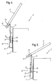
- the position of the cover 3 'shown in FIG. 4 essentially corresponds to that in FIG Figure 1 shown opening position of the lid 3 of the cooking device 1. In this position So there is a cooking basket attached to the lid 3 'outside the tub 7'.
- the cover 3 ' is rotatably mounted about an axis of rotation 5'.
- the cover is pivoted at least partially 3 'effected via a drive device 25.
- This drive device 25 comprises an electrical Drive unit 27, by means of which a lifting movement of a drive rod 29 can be forced is.
- This stroke movement of the drive rod 29 is in the form of a transmission element a gas spring 31 and a lever arm 33 in a rotational movement of the lid 3 'around Axis of rotation 5 'converted.
- the connection between the gas spring 31 and the drive rod 29 takes place via a joint element which is shown enlarged in FIG.
- the drive rod 29 ends in one fork-shaped receptacle 41 for a joint element 43 which is connected to the compressed gas spring 31 connected is.
- the hinge element 43 is also operatively connected to the pin 35, which engagement on both sides in grooves 37 formed in the U-shaped iron plate 39 are.
- FIG. 6 shows the position of the lid 3 'in which the tub 7' through the lid 3 ' is closed.
- the pin 35 is in the position of the cover shown in FIG 3 'at the lower stop of the groove 37 is a further pivoting of the cover 3 'possible in the horizontal position.
- This is made possible by the compressed gas spring 31.
- the gas spring 31 By using the gas spring 31 in the transmission element, it is thus achieved that a user at all times regardless of the drive device 25 Pivoting the lid 3 ', manually, can make. In particular, this is also the case possible if the cooking medium overheats within the tub 7 ' comes.
- the user pivots the lid 3 'against the force of the Compressed gas spring 31 in the position shown in Figure 6 and locks the lid 3 'in this Position via a locking device, not shown.
- the cover 3 'due to the stored in the gas spring 31 Energy opened automatically.
- the gas spring 31 is also achieved that this opening movement takes place in a controlled manner and no cracking of the deck ice 3 'takes place.
- Such a popping up would represent an increased risk for a user, since he is on the one hand could be hit by the lid 3 'or cooking medium from the vat 7' with one sprayed out by means of the lifting / lowering device attached to the lid 3 'cooking basket could be.
- the drive device 25 enables automatic lifting and lowering of a cooking basket can be achieved by pivoting the lid 3 '.
- the drive unit 27 with a control and regulation unit, not shown of the cooking device 1 'connected.
- input devices not shown
- the control and regulating unit then turns a cooking medium inside the tub 7 ' heated and by means of the drive unit 27 a cooking basket by a pivoting movement of the Lid 3 'lowered into the tub 7'.
- the specified cooking time has elapsed the cooking basket by means of a pivoting movement of the drive unit 27 Lid 3 'lifted from the tub 7'.
- control and regulating unit is connected to a weight sensor, which is in operative connection with the drive device 25.
- This sensor measures the force on the drive device 25 and thus the torque about the axis of rotation 5 ', whereby a determination of the weight of a food item in the cooking basket enables becomes. This determined value can then be used for cooking process control.
Landscapes
- Engineering & Computer Science (AREA)
- Food Science & Technology (AREA)
- Frying-Pans Or Fryers (AREA)
- Cookers (AREA)
Abstract
Description
- Figur 1
- eine Seitenschnittansicht eines Gargeräts mit einem erfindungsgemäßen Deckel im angehobenen Zustand eines Garkorbs;
- Figur 2
- eine Seitenschnittansicht des Gargeräts der Figur 1 in einer abgesenkten Position des Garkorbs;
- Figur 3
- eine Seitenschnittansicht des Gargeräts der Figuren 1 und 2 im geschlossenen Zustand des Deckels;
- Figur 4
- eine Detailseitenansicht einer Antriebsvorrichtung einer anderen Ausführungsform des erfindungsgemäßen Deckels in angehobener Position eines Garkorbs;
- Figur 5
- eine Detailseitenansicht der Antriebsvorrichtung der Figur 4 in abgesenkter Position des Garkorbs;
- Figur 6
- eine Detailseitenansicht der Antriebsvorrichtung der Figuren 4 und 5 im geschlossenen Zustand des Deckels; und
- Figur 7
- eine perspektivische Detailansicht eines Verbindungselements der Antriebsvorrichtung der Figuren 4 bis 6.
- 1, 1'
- Gargerät
- 3,3'
- Deckel
- 5, 5'
- Drehachse
- 7,7'
- Bottich
- 9
- Garmedium
- 11
- Garkorb
- 13
- Haken
- 15
- Gestänge
- 17
- Griff
- 19
- Biegung
- 21
- Rolle
- 23
- Lager
- 25
- Antriebsvorrichtung
- 27
- Antriebseinheit
- 29
- Antriebsstange
- 31
- Druckgasfeder
- 33
- Hebelarm
- 35
- Stift
- 37
- Nut
- 39
- Eisenplatte
- 41
- Aufnahme
- 43
- Gelenkelement
Claims (20)
- Deckel (3, 3') für ein Gargerät (1, 1') mit zumindest einem von dem Deckel (3, 3') zumindest teilweise verschließbaren ersten Garbehälter, insbesondere in Form eines Tiegels oder Bottichs (7, 7'), und zumindest einer Schwenkvorrichtung, über die der Deckel (3, 3') um eine im wesentlichen horizontal verlaufende Drehachse (5, 5') relativ zum Gargerät (1, 1') zwischen zumindest einer ersten, den ersten Garbehälter (7, 7'), insbesondere druckdicht, verschließenden Position und zumindest einer zweiten, den ersten Garbehälter (7, 7') öffnenden Position, insbesondere stufenlos, verschwenkbar ist, gekennzeichnet durch
zumindest eine Hebe-/Senkvorrichtung (13, 15, 17, 19, 21, 23) für zumindest einen zweiten Garbehälter, insbesondere in Form eines Garkorbs (11), über die der zweite Garbehälter (11) aus bzw. in den ersten Garbehälter (7) hebbar bzw. senkbar ist, wobei die Hebe-/Senkvorrichtung (13, 15, 17, 19, 21, 23) mit der Schwenkvorrichtung derart in Wirkverbindung steht, daß der zweite Garbehälter (11) durch Verschwenken des Deckels (3) aus zumindest einer dritten Position, in welcher der zweite Garbehälter (11) zumindest teilweise außerhalb und oberhalb des ersten Garbehälters (7) und/oder eines im ersten Garbehälter (7) einfüllbaren Garmediums (9) angeordnet ist, in zumindest eine vierte Position, in welcher der zweite Garbehälter (11) im wesentlichen in dem ersten Garbehälter (7) und/oder dem Garmedium (9) angeordnet ist, bewegbar ist. - Deckel nach Anspruch 1, gekennzeichnet durch
zumindest eine, insbesondere mechanische, elektromechanische, hydraulische, elektrohydraulische, pneumatische und/oder elektropneumatische, Antriebsvorrichtung (25), die vorzugsweise von der Schwenkvorrichtung und der Hebe-/Senkvorrichtung umfaßt ist. - Deckel nach Anspruch 1 oder 2, gekennzeichnet durch
zumindest eine Gegenkrafteinrichtung, insbesondere in Form einer Schrauben-, einer Spiral- und/oder Torsionsfeder und/oder umfassend zumindest ein Gegengewicht, zur Erleichterung des, insbesondere manuellen, Verschwenkens des Deckels zwischen der ersten und zweiten Position, wobei die Gegenkrafteinrichtung vorzugsweise in Wirkverbindung mit der Antriebsvorrichtung steht. - Deckel nach Anspruch 2 oder 3, dadurch gekennzeichnet, daß
die Antriebsvorrichtung (25) zumindest eine Antriebseinheit (27) und ein, vorzugsweise die Drehachse (5') des Deckels (3') mit der Antriebseinheit (27) verbindendes, Übertragungselement umfaßt,
das Übertragungselement zumindest ein erstes Verbindungselement, vorzugsweise in Form eines Hubzylinders und/oder einer ersten Federeinrichtung, insbesondere einer Druckgasfeder (31) und/oder Schraubenfeder, umfaßt, und
der Deckel (3'), vorzugsweise gegen die Kraft des Verbindungselements, manuell ohne Betätigung der Antriebseinheit (27), insbesondere in die erste Position, verschwenkbar ist. - Deckel nach einem der vorangehenden Ansprüche, dadurch gekennzeichnet, daß
der Deckel (3, 3') in zumindest einer zwischen der ersten und zweiten Position liegenden Position, insbesondere in der dritten und/oder vierten Position, arretierbar ist, vorzugsweise mittels der Antriebsvorrichtung (25). - Deckel nach Anspruch 5, dadurch gekennzeichnet, daß
das Übertragungselement, insbesondere das erste Verbindungselement (31), zum Arretieren des Deckels (3') zumindest einen, insbesondere mechanischen, Anschlag aufweist. - Deckel nach einem der vorangehenden Ansprüche, dadurch gekennzeichnet, daß
die Hebe-/Senkvorrichtung zumindest eine mit dem zweiten Garbehälter in Wirkverbindung stehende Tragevorrichtung, vorzugsweise in Form eines Gestänges (15), umfaßt,
die Tragevorrichtung lösbar mit zumindest einem zweiten Verbindungselement, vorzugsweise in Form eines am Deckel (3) angeordneten Hakens (13), verbindbar ist, und
die Verbindung zwischen dem Deckel (3) und dem zweiten Garbehälter (11), insbesondere bei einem Verschwenken des Deckels (3) in die erste Position, vorzugsweise automatisch, lösbar ist. - Deckel nach Anspruch 7, dadurch gekennzeichnet, daß
das Gestänge (15) bei bzw. nach einem Lösen der Verbindung zwischen dem Deckel (3) und dem zweiten Garbehälter (11) relativ zum Deckel (3), vorzugsweise mittels einer Rollvorrichtung (21), bewegbar ist. - Deckel nach Anspruch 7 oder 8, gekennzeichnet durch
zumindest eine zweite Federeinrichtung in Wirkverbindung mit dem zweiten Garbehälter (11) und der Tragevorrichtung, insbesondere zur Erleichterung des Verschwenkens aus der ersten Position heraus und/oder zum Auslenken des Gestänges (15). - Deckel nach einem der vorangehenden Ansprüche, gekennzeichnet durch
zumindest eine Sicherheitsvorrichtung, über die der Deckel bei der Durchführung eines Druckgarprozeßes innerhalb des ersten Garbehälters erst nach Ablassen des Drucks aus dem ersten Garbehälter aus der ersten Position heraus verschwenkbar ist. - Deckel nach einem der vorangehenden Ansprüche, gekennzeichnet durch
zumindest einen Sensor, insbesondere in Form eines Gewichtssensors, Rauchsensors, Drucksensors, Tempartursensors und/oder Positionssensors. - Deckel nach einem der vorangehenden Ansprüche, gekennzeichnet durch eine Ein- und/oder Ausgabeeinheit, insbesondere umfassend zumindest einen Schalter, eine Anzeige, einen Lautsprecher und/oder ein Mikrophon.
- Deckel nach einem der vorangehenden Ansprüche, gekennzeichnet durch
zumindest eine Steuer- und/oder Regeleinrichtung in Verbindung mit der Schwenkvorrichtung, der Hebe-/Senkvorrichtung, der Antriebsvorrichtung (25), der Antriebseinheit (27), der Gegenkrafteinrichtung, dem Übertragungselement, dem Anschlag, der Tragevorrichtung (15), dem ersten und/oder zweiten Verbindungselement (31, 13), der Sicherheitsvorrichtung, der ersten und/oder zweiten Federeinrichtung, der Rollvorrichtung (21), dem Sensor und/oder der Ein- und/oder Ausgabeeinheit. - Verfahren zum Betreiben eines Gargeräts, umfassend zumindest einen Deckel, insbesondere nach einem der vorangehenden Ansprüche, und einen zumindest teilweise mit dem Deckel verschließbaren ersten Garbehälter, insbesondere in Form eines Tiegels oder Bottichs, wobei der Deckel über eine Schwenkvorrichtung um eine im wesentlichen horizontal verlaufenden Drehachse relativ zum Gargerät zum Öffnen bzw. Verschließen des ersten Garbehälters in zumindest eine erste Position, in welcher der erste Garbehälter, insbesondere druckdicht, verschlossen wird, und eine zweite Position, in welcher der erste Garbehälter zugänglich wird, verschwenkt wird, dadurch gekennzeichnet, daß zumindest ein zweiter Garbehälter, insbesondere in Form eines Garkorbs, mittels einer vom Deckel umfaßten Hebe-/Senkvorrichtung in den ersten Garbehälter hinein- bzw. aus diesem herausbewegt wird, wobei der zweite Garbehälter durch Verschwenken des Dekkels aus zumindest einer dritten Position, in welcher der zweite Garbehälter zumindest teilweise oberhalb und außerhalb des ersten Garbehälters und/oder eines im ersten Garbehälter eingefüllten Garmediums positionert wird, in zumindest eine vierte Position, in welcher der zweite Garbehälter im wesentlichen in dem ersten Garbehälter und/oder dem Garmedium positioniert wird.
- Verfahren nach Anspruch 14, dadurch gekennzeichnet, daß
der Deckel mittels einer Antriebsvorrichtung, vorzugsweise automatisch, zumindest zwischen der dritten und vierten Position verschwenkt wird. - Verfahren nach Anspruch 14 oder 15, dadurch gekennzeichnet, daß
der Deckel zumindest in die erste Position manuell verschwenkt wird. - Verfahren nach einem der Ansprüche 14 bis 16, dadurch gekennzeichnet, daß
die Verbindung zwischen dem Deckel und dem zweiten Garbehälter gelöst werden kann, insbesondere beim Verschwenken in die erste Position. - Verfahren nach einem der Ansprüche 14 bis 17, dadurch gekennzeichnet, daß
der Deckel gesteuert und/oder geregelt bewegt wird in Abhängigkeit von dem Garmedium im ersten Garbehälter, einem Gargut im zweiten Garbehälter, einem Garverfahren und/oder einem Reinigungsverfahren. - Verfahren nach Anspruch 18, dadurch gekennzeichnet, daß
die Steuerung und/oder Regelung und/oder eine Diagnose über einen Datentransfer, insbesondere umfassend das Internet, durchgeführt wird. - Verfahren nach einem der Ansprüche 14 bis 19, dadurch gekennzeichnet, daß
der Deckel mit einem Benutzer kommuniziert über eine Ein- und/oder Ausgabeeinheit.
Applications Claiming Priority (2)
| Application Number | Priority Date | Filing Date | Title |
|---|---|---|---|
| DE10224465 | 2002-06-03 | ||
| DE10224465A DE10224465B4 (de) | 2002-06-03 | 2002-06-03 | Deckel für ein Gargerät |
Publications (2)
| Publication Number | Publication Date |
|---|---|
| EP1369071A1 true EP1369071A1 (de) | 2003-12-10 |
| EP1369071B1 EP1369071B1 (de) | 2005-05-11 |
Family
ID=29432572
Family Applications (1)
| Application Number | Title | Priority Date | Filing Date |
|---|---|---|---|
| EP03011095A Expired - Lifetime EP1369071B1 (de) | 2002-06-03 | 2003-05-21 | Deckel für ein Gargerät |
Country Status (2)
| Country | Link |
|---|---|
| EP (1) | EP1369071B1 (de) |
| DE (2) | DE10224465B4 (de) |
Cited By (2)
| Publication number | Priority date | Publication date | Assignee | Title |
|---|---|---|---|---|
| ITRM20090676A1 (it) * | 2009-12-22 | 2011-06-23 | Antica Pasticceria Artigianale S R L | Espositore da banco. |
| DE202016104337U1 (de) | 2015-10-22 | 2016-10-26 | Frima International Ag | Gargerät |
Families Citing this family (5)
| Publication number | Priority date | Publication date | Assignee | Title |
|---|---|---|---|---|
| DE102009042304A1 (de) * | 2009-09-19 | 2011-03-24 | Frank Domnick | Garvorrichtung und Verfahren zum Garen von Lebensmitteln |
| DE102010000327A1 (de) * | 2010-02-05 | 2011-08-11 | Maier, Max, 71636 | Pastakochgerät |
| DE102012015155A1 (de) * | 2012-07-31 | 2014-02-06 | Frima - T Sas | Gargerät mit Gewichtserkennung |
| CN103126536B (zh) * | 2013-02-28 | 2015-07-15 | 许锦标 | 适用于全自动炒菜机的锅盖控制装置 |
| DE202017101884U1 (de) | 2017-03-30 | 2017-06-01 | Frima International Ag | Gargerät |
Citations (4)
| Publication number | Priority date | Publication date | Assignee | Title |
|---|---|---|---|---|
| DE19653279A1 (de) * | 1996-12-20 | 1998-06-25 | Kueppersbusch | Gargerät für Lebensmittel |
| GB2321177A (en) * | 1997-01-18 | 1998-07-22 | Kenwood Marks Ltd | Combined basket handle and lid latch for deep fryer |
| US6022572A (en) * | 1997-12-05 | 2000-02-08 | Henny Penny Corporation | Apparatus and method for determining load size of food product |
| EP1275334A2 (de) * | 2001-07-12 | 2003-01-15 | Rational AG | Multifunktionaler Deckel für ein Gargerät |
Family Cites Families (3)
| Publication number | Priority date | Publication date | Assignee | Title |
|---|---|---|---|---|
| US4930408A (en) * | 1988-12-13 | 1990-06-05 | Henny Penny Corporation | Large capacity pressure cooker |
| FR2736978B1 (fr) * | 1995-07-21 | 1998-12-24 | Moulinex Sa | Charniere pour couvercle de boitier d'appareil de cuisson et son procede de montage |
| DE10005003B4 (de) * | 2000-02-04 | 2004-09-02 | Juno Großküchen GmbH | Garsystem mit Rohrkonstruktion |
-
2002
- 2002-06-03 DE DE10224465A patent/DE10224465B4/de not_active Expired - Fee Related
-
2003
- 2003-05-21 EP EP03011095A patent/EP1369071B1/de not_active Expired - Lifetime
- 2003-05-21 DE DE50300527T patent/DE50300527D1/de not_active Expired - Lifetime
Patent Citations (4)
| Publication number | Priority date | Publication date | Assignee | Title |
|---|---|---|---|---|
| DE19653279A1 (de) * | 1996-12-20 | 1998-06-25 | Kueppersbusch | Gargerät für Lebensmittel |
| GB2321177A (en) * | 1997-01-18 | 1998-07-22 | Kenwood Marks Ltd | Combined basket handle and lid latch for deep fryer |
| US6022572A (en) * | 1997-12-05 | 2000-02-08 | Henny Penny Corporation | Apparatus and method for determining load size of food product |
| EP1275334A2 (de) * | 2001-07-12 | 2003-01-15 | Rational AG | Multifunktionaler Deckel für ein Gargerät |
Cited By (4)
| Publication number | Priority date | Publication date | Assignee | Title |
|---|---|---|---|---|
| ITRM20090676A1 (it) * | 2009-12-22 | 2011-06-23 | Antica Pasticceria Artigianale S R L | Espositore da banco. |
| DE202016104337U1 (de) | 2015-10-22 | 2016-10-26 | Frima International Ag | Gargerät |
| DE102015118062A1 (de) | 2015-10-22 | 2017-04-27 | Frima International Ag | Gargerät und Verfahren zum Betreiben eines Gargeräts |
| DE102015118062B4 (de) | 2015-10-22 | 2020-07-30 | Rational International Ag | Gargerät und Verfahren zum Betreiben eines Gargeräts |
Also Published As
| Publication number | Publication date |
|---|---|
| DE10224465B4 (de) | 2004-04-08 |
| EP1369071B1 (de) | 2005-05-11 |
| DE10224465A1 (de) | 2003-12-18 |
| DE50300527D1 (de) | 2005-06-16 |
Similar Documents
| Publication | Publication Date | Title |
|---|---|---|
| DE102005020744B3 (de) | Verfahren zum Führen eines Garprozesses unter Berücksichtigung des Öffnungsgrades zumindest einer Garraumöffnung und Gargerät zur Durchführung solch eines Verfahrens | |
| EP1369072B1 (de) | Deckel für ein Gargerät | |
| EP1369071B1 (de) | Deckel für ein Gargerät | |
| DE10005003B4 (de) | Garsystem mit Rohrkonstruktion | |
| DE4427122A1 (de) | Haushaltgerät, insbesondere Geschirrspülmaschine oder Herd mit einer schwenkbar am Gerätegehäuse gelagerten Gerätetür | |
| DE19620973A1 (de) | Aufnahmebox für den Unterflureinbau | |
| DE3922839A1 (de) | Beschickungstuer fuer ein haushaltgeraet | |
| DE19653279A1 (de) | Gargerät für Lebensmittel | |
| DE19537135A1 (de) | Schrank- oder Regaleinrichtung | |
| EP3655703A1 (de) | Gargerät-einheit sowie gargerät-untergestell | |
| DE3631796A1 (de) | Einrichtung zum versorgen der kanone eines panzerfahrzeuges mit munition | |
| EP1788918B1 (de) | Frittiergerät | |
| DE102015118062B4 (de) | Gargerät und Verfahren zum Betreiben eines Gargeräts | |
| DE60218086T2 (de) | Kochtopf mit Sicherheitsdeckel | |
| DE19608175A1 (de) | Grillgerät | |
| DE2334327C3 (de) | Tragbares, zusammenklappbares Koch- und Bratgerät | |
| DE602005000164T2 (de) | Haushaltsgerät aus scharnierartig verbundenen Rostelementen | |
| DE20312397U1 (de) | Kippbarer oder verschwenkbarer Tiegel für ein Gargerät | |
| DE2205488C3 (de) | Aushängbare Bratofentür | |
| DE285542C (de) | ||
| DE141307C (de) | ||
| DE202007010955U1 (de) | Wasserfiltergerät | |
| DE1679273C3 (de) | Ölofen mit einer herausführbaren Brennerschale | |
| DE202019104796U1 (de) | Kamado-Grill mit abnehmbarem Deckel | |
| DE600119C (de) | Schiebefenster mit Gegengewicht und schwenkbar am Fensterrahmen gelagerten Fuehrungsmitteln fuer das Fenster |
Legal Events
| Date | Code | Title | Description |
|---|---|---|---|
| PUAI | Public reference made under article 153(3) epc to a published international application that has entered the european phase |
Free format text: ORIGINAL CODE: 0009012 |
|
| AK | Designated contracting states |
Kind code of ref document: A1 Designated state(s): AT BE BG CH CY CZ DE DK EE ES FI FR GB GR HU IE IT LI LU MC NL PT RO SE SI SK TR |
|
| AX | Request for extension of the european patent |
Extension state: AL LT LV MK |
|
| 17P | Request for examination filed |
Effective date: 20040109 |
|
| AKX | Designation fees paid |
Designated state(s): DE FR GB IT |
|
| GRAP | Despatch of communication of intention to grant a patent |
Free format text: ORIGINAL CODE: EPIDOSNIGR1 |
|
| GRAS | Grant fee paid |
Free format text: ORIGINAL CODE: EPIDOSNIGR3 |
|
| GRAA | (expected) grant |
Free format text: ORIGINAL CODE: 0009210 |
|
| AK | Designated contracting states |
Kind code of ref document: B1 Designated state(s): DE FR GB IT |
|
| REG | Reference to a national code |
Ref country code: GB Ref legal event code: FG4D Free format text: NOT ENGLISH |
|
| REG | Reference to a national code |
Ref country code: IE Ref legal event code: FG4D Free format text: LANGUAGE OF EP DOCUMENT: GERMAN |
|
| REF | Corresponds to: |
Ref document number: 50300527 Country of ref document: DE Date of ref document: 20050616 Kind code of ref document: P |
|
| GBT | Gb: translation of ep patent filed (gb section 77(6)(a)/1977) |
Effective date: 20050913 |
|
| PLBE | No opposition filed within time limit |
Free format text: ORIGINAL CODE: 0009261 |
|
| STAA | Information on the status of an ep patent application or granted ep patent |
Free format text: STATUS: NO OPPOSITION FILED WITHIN TIME LIMIT |
|
| ET | Fr: translation filed | ||
| 26N | No opposition filed |
Effective date: 20060214 |
|
| PGFP | Annual fee paid to national office [announced via postgrant information from national office to epo] |
Ref country code: GB Payment date: 20140520 Year of fee payment: 12 |
|
| GBPC | Gb: european patent ceased through non-payment of renewal fee |
Effective date: 20150521 |
|
| PG25 | Lapsed in a contracting state [announced via postgrant information from national office to epo] |
Ref country code: GB Free format text: LAPSE BECAUSE OF NON-PAYMENT OF DUE FEES Effective date: 20150521 |
|
| REG | Reference to a national code |
Ref country code: FR Ref legal event code: PLFP Year of fee payment: 14 |
|
| REG | Reference to a national code |
Ref country code: FR Ref legal event code: PLFP Year of fee payment: 15 |
|
| REG | Reference to a national code |
Ref country code: FR Ref legal event code: PLFP Year of fee payment: 16 |
|
| PGFP | Annual fee paid to national office [announced via postgrant information from national office to epo] |
Ref country code: IT Payment date: 20220531 Year of fee payment: 20 Ref country code: FR Payment date: 20220523 Year of fee payment: 20 Ref country code: DE Payment date: 20220519 Year of fee payment: 20 |
|
| REG | Reference to a national code |
Ref country code: DE Ref legal event code: R071 Ref document number: 50300527 Country of ref document: DE |