EP1367014B1 - Einrichtung für die Zuführung von Zuschnitten - Google Patents
Einrichtung für die Zuführung von Zuschnitten Download PDFInfo
- Publication number
- EP1367014B1 EP1367014B1 EP20030009658 EP03009658A EP1367014B1 EP 1367014 B1 EP1367014 B1 EP 1367014B1 EP 20030009658 EP20030009658 EP 20030009658 EP 03009658 A EP03009658 A EP 03009658A EP 1367014 B1 EP1367014 B1 EP 1367014B1
- Authority
- EP
- European Patent Office
- Prior art keywords
- stack
- blanks
- blank
- carrier part
- chamber
- Prior art date
- Legal status (The legal status is an assumption and is not a legal conclusion. Google has not performed a legal analysis and makes no representation as to the accuracy of the status listed.)
- Expired - Lifetime
Links
- 238000004806 packaging method and process Methods 0.000 claims description 4
- 238000012545 processing Methods 0.000 claims description 4
- 230000013011 mating Effects 0.000 claims description 2
- 239000013589 supplement Substances 0.000 claims 1
- 238000000926 separation method Methods 0.000 description 5
- 238000012546 transfer Methods 0.000 description 3
- 230000015572 biosynthetic process Effects 0.000 description 2
- 239000000969 carrier Substances 0.000 description 2
- 235000019504 cigarettes Nutrition 0.000 description 2
- 238000000034 method Methods 0.000 description 2
- 210000000056 organ Anatomy 0.000 description 2
- 238000000151 deposition Methods 0.000 description 1
- 238000013461 design Methods 0.000 description 1
- 238000003780 insertion Methods 0.000 description 1
- 230000037431 insertion Effects 0.000 description 1
- 230000003993 interaction Effects 0.000 description 1
- 238000012536 packaging technology Methods 0.000 description 1
- 230000002093 peripheral effect Effects 0.000 description 1
- 230000000284 resting effect Effects 0.000 description 1
- 125000006850 spacer group Chemical group 0.000 description 1
- 230000002123 temporal effect Effects 0.000 description 1
Images


Classifications
-
- B—PERFORMING OPERATIONS; TRANSPORTING
- B65—CONVEYING; PACKING; STORING; HANDLING THIN OR FILAMENTARY MATERIAL
- B65H—HANDLING THIN OR FILAMENTARY MATERIAL, e.g. SHEETS, WEBS, CABLES
- B65H1/00—Supports or magazines for piles from which articles are to be separated
- B65H1/30—Supports or magazines for piles from which articles are to be separated with means for replenishing the pile during continuous separation of articles therefrom
-
- B—PERFORMING OPERATIONS; TRANSPORTING
- B65—CONVEYING; PACKING; STORING; HANDLING THIN OR FILAMENTARY MATERIAL
- B65H—HANDLING THIN OR FILAMENTARY MATERIAL, e.g. SHEETS, WEBS, CABLES
- B65H2301/00—Handling processes for sheets or webs
- B65H2301/40—Type of handling process
- B65H2301/42—Piling, depiling, handling piles
- B65H2301/422—Handling piles, sets or stacks of articles
- B65H2301/4226—Delivering, advancing piles
- B65H2301/42264—Delivering, advancing piles by moving the surface supporting the lowermost article of the pile, e.g. conveyor, carriage
-
- B—PERFORMING OPERATIONS; TRANSPORTING
- B65—CONVEYING; PACKING; STORING; HANDLING THIN OR FILAMENTARY MATERIAL
- B65H—HANDLING THIN OR FILAMENTARY MATERIAL, e.g. SHEETS, WEBS, CABLES
- B65H2555/00—Actuating means
- B65H2555/30—Multi-axis
-
- B—PERFORMING OPERATIONS; TRANSPORTING
- B65—CONVEYING; PACKING; STORING; HANDLING THIN OR FILAMENTARY MATERIAL
- B65H—HANDLING THIN OR FILAMENTARY MATERIAL, e.g. SHEETS, WEBS, CABLES
- B65H2701/00—Handled material; Storage means
- B65H2701/10—Handled articles or webs
- B65H2701/17—Nature of material
- B65H2701/176—Cardboard
- B65H2701/1764—Cut-out, single-layer, e.g. flat blanks for boxes
Definitions
- the invention relates to a device for the supply of stacked blanks from paper, plastic or the like, so from blank stacks, to a Processing station, in particular packaging machine, wherein the blank stacks successively a container with stacking chambers for each blank stack by a stack conveyor with an entering into the stacking chamber Support member can be removed and fed to a separating unit.
- the blanks delivered as blank stacks - tax banderoles, coupons and other print carriers for cigarette packs - are in the field of packaging machine be handled reliably without manual intervention.
- the shafts or blank stacks are successively one Separation unit supplied and the blanks individually conveyed off (DE 197 30 307). The performance of this device is not yet satisfactory.
- a device for handling stacks of sheets is known (US Pat. No. 5,171,125).
- the stacks of sheets are fed in containers with four stacking chambers. each Stacking chamber has an upright slot on an outer wall of the container on.
- a support arm of a fixedly positioned stack lifter occur.
- the support arm is movable upwards with the stack of sheets, the stack of sheets introduced into a designed as a hollow body, bottom open stack receptacle becomes. This is then pivoted with the stack, the lower, open Side closed by the corresponding arcuate support arm becomes.
- An effective in the inclined position belt conveyor leads the individual Leaves off.
- the pile holder can only after complete emptying into the starting position to return. As a result, this device is too low Performance can not be used for packaging technology.
- the invention is based on the object, a device for the transfer of (small) blanks to a processing station to propose in the larger Quantities of blanks or blank stacks reliable without manual intervention can be processed.
- the core of the invention is the interaction of a specially trained Containers with a plurality of stacking chambers for each blank stack and a stack conveyor with a consisting of support member and guide member Bracket.
- This holder is designed so that a recorded and transported blank stack in an analogous manner in the area of a separating unit can be deducted in a position shaft positioned there.
- the blanks 10 are available as a larger stack, ie as a blank stack 11 placed and in a separation unit 12 successively at the bottom of the blank stacks 11 conveyed away and along two blank sheets 13, 14 in scaly Formation of a processing station, for example a packaging machine (not shown) supplied.
- the separating unit 12 consists of two cutting stations 15, 16. These are offset in height from each other and in plan view seen side by side. Each cutting station 15, 16 has a blank stock on. This is located in an upright cut shaft 17, 18. Each at the Underside of the fixed blanking shaft 17, 18, the blanks 10 through a removal organ carried away.
- Each blank slot 17, 18 is as a pre- or temporary storage for blanks 10 a Attachment shaft 19, 20 assigned. This takes a predetermined amount of blanks 10, namely a blank stack 11.
- the attachment shaft 19, 20 is on top the blanking shaft 17, 18 placed, so that the blanks 10 and the blank stacks 11 from the attachment shaft 19, 20 gradually in the blanking shaft 17, 18 can drain. When the top chute 19, 20 is emptied, this is the next blank stack 11 fed while still blanks 10 from the blank slot 17, 18 are taken.
- the blank stacks 11 are removed from a large-volume container, namely a Container 21. In this a plurality of blank stacks 11 is aligned in rows positioned. At least one blank stack 11 is fed through a stack conveyor 22 taken. This is designed as a lifting conveyor or like a robot with a Swivel arm 23, which has two articulated arms 24, 25. The stack conveyor 22 and its Boom or swing arm 23 is rotatable about a vertical axis.
- the robot or stack conveyor 22 is arranged on a support frame, namely on a vertical conveyor 26.
- Filled containers 21 are from a lower receiving position promoted upwards, in the area of the upper blanking station 15 or to the level of the underlying blanking station 16.
- the (filled) container 21st can the vertical conveyor 26 by a horizontal conveyor, not shown, or of Hand fed.
- Figure 2 are two Stations for container 21 provided, so two vertical conveyor 26 for the container 21, wherein the robot or stack conveyor 22 centrally between the two vertical conveyors 26th is positioned and thus empty the container 21 kept ready on both sides can.
- a lifting head or a Holder 27 for detecting and transporting and depositing each a blank stack 11 attached.
- the holder 27 is formed in a special way exists namely from a support member 28 for a blank stack 11 and a guide member 29.
- the support member 28 is relative to the guide member 29, but also relative to the articulated arm 25th movable up and down.
- Both legs 30, 31 are connected by an upright web 32 with each other connected, so that the support member 28 is formed a total of U-shaped.
- the cut pile 11 is during handling by the staple conveyor 22 on the lower Carrying leg 30 on.
- the counter-leg 31 is located at the top of the Blank stack 11, while the web 32 forms a lateral support.
- the organs, namely legs 30, 31 are arranged in fixed relative position to each other, so that the blank stack 10 is received without clamping action.
- the thus formed support member 28 works together with the guide member 29, which as a downwardly open shaft is formed with a U- or C-shaped cross-sectional contour (Fig. 8).
- the support member 28 is movable up and down within the guide member 29, wherein the web 32 in the region of an upright recess or an upright Slit 33 extends in at least one side wall of the guide member 29.
- the Legs 30, 31 pass through this slot 33 when a blank stack 11 in the guide member 29 is introduced by upward movement of the support member 28 or vice versa is moved out.
- Within the thus formed holder 27 is the blank stack 11 supported on all upright sides and lies on the bottom of the support leg 30 (position according to FIG. 7 or according to FIG. 10).
- the guide member 29 is fixedly connected to the boom or pivot arm 23, namely to the end of the articulated arm 25. At this a support piece 34 is attached to a transversely or horizontally projecting support arm 35. At this turn, the holder is 27th attached or the guide member 29th
- a lifting member for the up and Abmony of the support member 28 attached namely a pressure medium or pneumatic cylinder 36.
- Its piston rod 37 is connected to the support member 28, at the Outer side thereof in the region of the upright web 32, such that the (lower) End of the piston rod 37 is always above the support member 28.
- the cylinder 36 or the piston rod 37 is movable so that in a lower end position, the support member 28 completely outside of the guide member 29 is (Fig. 5, Fig. 6, Fig. 11, Fig. 12). In the other, upper end position is the support member 28 - with blank stack 11 - completely within the guide part 29.
- the support arm 35 is rotatable or pivotable on Support piece 34 is attached, so that the holder 27 (also) about a vertical axis is pivotable.
- the containers 21 are designed to provide a mechanized removal the blank stack 11 by the stack conveyor 22 to allow.
- the blank stacks 11 are arranged in compartments or chambers within the container 21 so that a Access of the holder 27 and the support member 28 for detecting and lifting a Blank stack 11 is possible.
- upright stacking chambers 38 are inside of the container 21, which are partially open on at least one side for attaching the support member.
- a plurality of parallel inner walls 39 are in the container 21 arranged a plurality of parallel inner walls 39. These run parallel to each other and at a distance corresponding to the width of a blank stack 11. Transverse to these inner walls 39 only partial walls are provided, namely opposite each other upright dividers 40.
- each row of stacking chambers 38 is assigned such an empty chamber 41, which is partially open to the adjacent stacking chamber 38, namely under formation an upright opening analogous to the slot 33rd
- the Holder 27 For the removal of a (first) blank stack 11 from a container 21 is the Holder 27 is moved by the pivoting arm 23 into a position above the container 21, and aligned on an edge-side empty chamber 41.
- the support member 28 is located initially completely within the guide part 29. Above the empty chamber 41st the support member 28 is lowered and introduced into the empty chamber 41.
- transverse movement FIG. 6
- a blank stack 11 is placed in a first, adjacent stacking chamber 38 detected (Fig. 6).
- the support leg 30 passes under the relevant blank stack 11th
- This process for detecting a blank stack 11 is characterized by another particular Detail of the container 21 allows.
- the blank stacks 11 are actually resting at the bottom on (lateral) spacers or projections 42, such that in the middle of a free space 43rd is created below the blank stack 11.
- This clearance 43 extends into the area of the empty chamber 41, so that in this located support member 28 at the Receiving a blank stack 11 with the lower support leg 30 pass under this can.
- the transfer of a blank stack 11 by the holder 27 to one or the other Cutting station 15, 16 takes place in an analogous manner with kinematic reversal of movement processes relative to Fig. 5 to Fig. 7.
- the holder 27 is connected to the blank stack 11 through the stack conveyor 22 in a position above the blanking shaft or the attachment shaft 19, 20 driven (Fig. 10).
- the Carrying member 28 With exact alignment is the Carrying member 28 with the blank stack 11 downwardly moved into the shaft or attachment shaft 19, 20. This is formed in cross section in the same or similar manner as the guide member 29 (Fig. 8).
- the support member 28 is moved so far down that the blank stack 11 is located entirely within the attachment shaft 19, 20 (FIG. 11).
- the blank stack 11 is set down on a support or support, namely on a (fork-shaped) support plate 44. This is from the side by a (Pressure medium) cylinder 45 inserted into the top chute 19, 20.
- the support plate 44 forms a temporary lower end of the attachment shaft 19, 20 relative to the respective Cutting shaft 17, 18.
- the holder is now moved overall in the position shown in FIG. 12.
- the support member 28 leaves the attachment shaft 19, 20.
- the support plate 44 is sideways withdrawn from the attachment shaft 19, 20.
- the blank stack 11 can now (Under dead weight) are moved down to the connection to a residual stack 46th in the cutting shaft 17, 18. This temporarily forms a unit with the attachment shaft 19, 20, until the emptying of the attachment shaft 19, 20. Thereafter, an exchange takes place or a (new) filling of the attachment shaft 19, 20.
- Each cut shaft 17, 18 are associated with several, namely two essay shafts 19a, b, 20a, b. These are transversely movable.
- a first attachment shaft 19a, 20a is located in a vertical plane offset to the cut-out shaft 17, 18, namely in a loading position (Fig. 3). In this position, the attachment shaft 19a, 20a in the described Way charged. Meanwhile, there is a second essay shaft 19b, 20b in a discharge position above the respective blanks 17, 18. After emptying the attachment shaft 19b, 20b this is transversely displaced in a to Blank shaft 17, 18 staggered position (dashed lines in Fig. 3).
- the filled Attachment shaft 19a, 20a moved to the position above the blanking shaft 17, 18.
- Filling a top chute 19, 20 and emptying a (other) top chute run simultaneously or with temporal overlap.
- the tower shafts 19a, 19b and 20a, 20b are displaceable by transverse drives 47.
- the each other associated top ducts 19a, 19b on the one hand and 20a, 20b on the other hand are on a (horizontal) transverse guide 48 attached. This in turn is about a support frame 49 connected to a machine frame of the separating unit 12.
Landscapes
- Engineering & Computer Science (AREA)
- Mechanical Engineering (AREA)
- Making Paper Articles (AREA)
- Supplying Of Containers To The Packaging Station (AREA)
- Specific Conveyance Elements (AREA)
Description
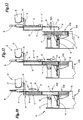
- Fig. 1
- eine Einrichtung mit Vereinzelungsaggregat und Beschickungsstation in Seitenansicht,
- Fig. 2
- die Einrichtung gemäß Fig. 1 in Draufsicht entsprechend Pfeil II der Fig. 1,
- Fig. 3
- eine Seitenansicht bzw. ein Vertikalschnitt in der Schnittebene III-III der Fig. 1,
- Fig. 4
- das Vereinzelungsaggregat als Einzelheit entsprechend Ausschnitt IV in Fig. 1,
- Fig. 5 bis Fig. 7
- Phasen bei der Aufnahme eines Zuschnittstapels aus einem Behälter bzw. Container im Vertikalschnitt des Containers,
- Fig. 8
- einen Horizontalschnitt durch einen Hubkopf bzw. eine Aufnahme des Stapelförderers im Horizontalschnitt VIII-VIII der Fig. 7,
- Fig. 9
- einen Detailausschnitt des Behälters bzw. Containers in einer vertikalen bodenseitigen Schnittebene IX-IX der Fig. 6,
- Fig. 10 bis Fig. 12
- Phasen der Übergabe eines Zuschnittstapels durch die Halterung des Stapelförderers an das Vereinzelungsaggregat in Seitenansicht bzw. im Vertikalschnitt.
- 10
- Zuschnitt
- 11
- Zuschnittstapel
- 12
- Vereinzelungsaggregat
- 13
- Zuschnittbahn
- 14
- Zuschnittbahn
- 15
- Zuschnittstation
- 16
- Zuschnittstation
- 17
- Zuschnittschacht
- 18
- Zuschnittschacht
- 19
- Aufsatzschacht
- 19a
- Aufsatzschacht
- 19b
- Aufsatzschacht
- 20
- Aufsatzschacht
- 20a
- Aufsatzschacht
- 20b
- Aufsatzschacht
- 21
- Container
- 22
- Stapelförderer
- 23
- Schwenkarm
- 24
- Gelenkarm
- 25
- Gelenkarm
- 26
- Vertikalförderer
- 27
- Halterung
- 28
- Tragteil
- 29
- Führungsteil
- 30
- Tragschenkel
- 31
- Gegenschenkel
- 32
- Steg
- 33
- Schlitz
- 34
- Tragstück
- 35
- Tragarm
- 36
- Zylinder
- 37
- Kolbenstange
- 38
- Stapelkammer
- 39
- Innenwand
- 40
- Trennsteg
- 41
- Leerkammer
- 42
- Vorsprung
- 43
- Freiraum
- 44
- Tragplatte
- 45
- Zylinder
- 46
- Reststapel
- 47
- Querantrieb
- 48
- Querführung
- 49
- Traggestell
Claims (11)
- Einrichtung für die Zuführung von gestapelten Zuschnitten (10) aus Papier, Kunststoff oder dergleichen, also von Zuschnittstapeln (11), zu einer Verarbeitungsstation, insbesondere Verpackungsmaschine, wobei die Zuschnittstapel (11) nacheinander einem Container (21) mit Stapelkammern (38) für je einen Zuschnittstapel (11) durch einen Stapelförderer (22) mit einem in die Stapelkammer (38) eintretenden Tragteil (28) entnehmbar und einem Vereinzelungsaggregat (12) zuführbar sind, gekennzeichnet durch folgende Merkmale:a) das Tragteil (28) ist Teil einer am Stapelförderer (22) angebrachten Halterung (27) und weist einen unteren Tragschenkel (30) auf, der beim Einführen des Tragteils (28) in eine Stapelkammer (38) unter den Zuschnitt (11) bewegbar ist, derart, dass der Zuschnittstapel (11) bei Aufwärtsbewegung des Tragteils (28) auf dem Tragschenkel (30) ruht,b) das Tragteil (28) ist mit einem erfassten Zuschnittstapel (11) durch Aufwärtsbewegung in ein feststehendes Führungsteil (29) der Halterung (27) einfahrbar, derart, dass der Zuschnittstapel (11) innerhalb des Führungsteils (29) allseitig abgestützt ist,c) der Zuschnittstapel (11) ist mit dem Tragteil (28) innerhalb des Führungsteils (29) dem Vereinzelungsaggregat (12) zuführbar.
- Einrichtung nach Anspruch 1, dadurch gekennzeichnet, dass das Tragteil (28) über eine mindestens teilweise offene, aufrechte Seite in die Stapelkammer (38) des Containers (21) durch Querbewegung einführbar ist zum Erfassen eines Zuschnittstapels (11).
- Einrichtung nach Anspruch 1 oder 2, dadurch gekennzeichnet, dass randseitig innerhalb des Containers (21) ein Raum für den Eintritt des Tragteils (28) zum Erfassen eines ersten Zuschnittstapels (11) gebildet ist, insbesondere eine Leerkammer (41) und dass zum Erfassen nachfolgender Zuschnittstapel (11) das Tragteil (28) in eine freie Stapelkammer (38) benachbart zu der zu entleerenden Stapelkammer (38) einführbar ist.
- Einrichtung nach Anspruch 3 oder einem der weiteren Ansprüche, dadurch gekennzeichnet, dass die Stapelkammern (38) im Container (21) in Reihen angeordnet sind mit einer randseitigen Leerkammer (41) für jede Reihe von Stapelkammern (38).
- Einrichtung nach Anspruch 1 oder einem der weiteren Ansprüche, dadurch gekennzeichnet, dass jede Stapelkammer (38) bodenseitig Vorsprünge (42) aufweist, die an aufrechten Wänden der Stapelkammer (38) angeordnet sind und auf denen die Zuschnittstapel (11) aufliegen unter Bildung eines Freiraums (43) unter jedem Zuschnittstapel (11) für den Eintritt des Tragschenkels (30) des Tragteils (28).
- Einrichtung nach Anspruch 1 oder einem der weiteren Ansprüche, dadurch gekennzeichnet, dass die Halterung (27) aus dem unteren Tragschenkel (30), einem oberen Gegenschenkel (31) an der Oberseite des erfassten Zuschnittstapels (11) und aus einem die beiden Schenkel (30, 31) miteinander verbindenden aufrechten Steg (32) besteht.
- Einrichtung nach Anspruch 6, dadurch gekennzeichnet, dass am Führungsteil (29) ein Zylinder (36) angebracht ist mit einer nach unten ausfahrbaren Kolbenstange (37), die mit dem Tragteil (28) verbunden ist, wobei das Tragteil (28) durch den Zylinder (36) bzw. die Kolbenstange (37) aus der unteren Aufnahmezustellung für einen Zuschnittstapel (11) in der Stapelkammer (38) und einer oberen Endstellung des Tragteils (28) im Führungsteil (29) bewegbar ist.
- Einrichtung nach Anspruch 1, gekennzeichnet durch folgende Merkmale:a) das Vereinzelungsaggregat (12) weist zur Bildung eines Vorrats an Zuschnitten (10) im Bereich einer Zuschnittstation (15, 16) einen feststehenden Zuschnittschacht (17, 18) auf zur Aufnahme mindestens eines Teils eines Zuschnittstapels (11),b) ein mit einem Zuschnittstapel (11) gefüllter Aufsatzschacht (19, 20) ist auf den Zuschnittschacht (17, 18) aufsetzbar zur Ergänzung bzw. Vergrößerung des Vorrats an Zuschnitten (10),c) der Zuschnittstapel (11) ist durch das Tragteil (28) der Halterung (27) von oben in den oben offenen Aufsatzschacht (19, 20) einführbar durch Abwärtsbewegung des Tragteils (28) mit Zuschnittstapel (11),d) das Tragteil (28) ist durch Querbewegung nach Absetzen des Zuschnittstapels (11) aus dem Aufsatzschacht (19, 20) seitlich herausfahrbar.
- Einrichtung nach Anspruch 8 oder einem der weiteren Ansprüche, dadurch gekennzeichnet, dass das Vereinzelungsaggregat (12) mehrere, vorzugsweise zwei Zuschnittstationen (15, 16) aufweist, die vorzugsweise in der Höhe sowie in Horizontalrichtung versetzt zueinander angeordnet sind, wobei die Zuschnittstationen (15, 16) durch einen gemeinsamen Stapelförderer (22) beschickbar sind.
- Einrichtung nach Anspruch 8 oder einem der weiteren Ansprüche, dadurch gekennzeichnet, dass der Aufsatzschacht (19, 20) zur Befüllung mit einem Zuschnittstapel (11) durch Querbewegung in eine gegenüber dem Zuschnittschacht (17, 18) versetzten Füllstation verschiebbar ist, wobei jeder Zuschnittstation (15, 16) bzw. jedem Zuschnittschacht (17, 18) zwei Aufsatzschächte (19a, 19b bzw. 20a, 20b) zugeordnet sind, die wechselweise in eine Befüllungsstellung sowie in eine Entleerungsstellung oberhalb des zugeordneten Zuschnittschachts (17, 18) querbewegbar sind.
- Einrichtung nach Anspruch 1 oder einem der weiteren Ansprüche, dadurch gekennzeichnet, dass die Container (21) mit den Zuschnittstapeln (11) durch einen Vertikalförderer (26) in eine erhöhte Entladungsstellung relativ zum Stapelförderer (22) bewegbar sind.
Applications Claiming Priority (2)
| Application Number | Priority Date | Filing Date | Title |
|---|---|---|---|
| DE2002124551 DE10224551A1 (de) | 2002-05-30 | 2002-05-30 | Einrichtung für die Zuführung von Zuschnitten |
| DE10224551 | 2002-05-30 |
Publications (2)
| Publication Number | Publication Date |
|---|---|
| EP1367014A1 EP1367014A1 (de) | 2003-12-03 |
| EP1367014B1 true EP1367014B1 (de) | 2005-12-14 |
Family
ID=29414302
Family Applications (1)
| Application Number | Title | Priority Date | Filing Date |
|---|---|---|---|
| EP20030009658 Expired - Lifetime EP1367014B1 (de) | 2002-05-30 | 2003-04-30 | Einrichtung für die Zuführung von Zuschnitten |
Country Status (2)
| Country | Link |
|---|---|
| EP (1) | EP1367014B1 (de) |
| DE (2) | DE10224551A1 (de) |
Families Citing this family (3)
| Publication number | Priority date | Publication date | Assignee | Title |
|---|---|---|---|---|
| IT1391713B1 (it) * | 2008-09-18 | 2012-01-27 | Gd Spa | Unità di alimentazione di pile di materiale di incarto ad una macchina impacchettatrice. |
| DE102009050712A1 (de) * | 2009-10-26 | 2011-04-28 | Focke & Co.(Gmbh & Co. Kg) | Verfahren und Vorrichtung zum Handhaben von Zuschnitten aus Verpackungsmaterial für Zigarettenpackungen |
| DE102013011884A1 (de) * | 2013-07-17 | 2015-01-22 | Focke & Co. (Gmbh & Co. Kg) | Verfahren und Vorrichtung zur Herstellung von Packungen für Zigaretten |
Family Cites Families (6)
| Publication number | Priority date | Publication date | Assignee | Title |
|---|---|---|---|---|
| DE3627868A1 (de) * | 1986-08-16 | 1988-02-18 | Focke & Co | Vorrichtung zum zufuehren von zuschnitten zu einer verpackungsmaschine |
| DE3827915A1 (de) * | 1988-08-17 | 1990-03-01 | Focke & Co | Einrichtung zum zufuehren von (packungs-) zuschnitten zu einer verpackungsmaschine |
| US5171125A (en) * | 1988-10-24 | 1992-12-15 | Am International Incorporated | Sheet material handling apparatus and method having a pivotable hopper and bottom feeder |
| IT1233670B (it) * | 1989-08-01 | 1992-04-13 | Gd Spa | Apparecchiatura per alimentare macchine confezionatrici con pile di materiale in foglio |
| DE19730307A1 (de) * | 1997-07-15 | 1999-01-21 | Focke & Co | Verfahren und Vorrichtung zum Handhaben von Banderolen bei der Übergabe an (Zigaretten-) Packungen |
| NL1017134C2 (nl) * | 2001-01-17 | 2002-07-18 | Fountain Tech Bv | Inrichting en werkwijze voor het aanvoeren van producten, in het bijzonder velvormige producten zoals in mould labels. |
-
2002
- 2002-05-30 DE DE2002124551 patent/DE10224551A1/de not_active Withdrawn
-
2003
- 2003-04-30 DE DE50301896T patent/DE50301896D1/de not_active Expired - Lifetime
- 2003-04-30 EP EP20030009658 patent/EP1367014B1/de not_active Expired - Lifetime
Also Published As
| Publication number | Publication date |
|---|---|
| EP1367014A1 (de) | 2003-12-03 |
| DE50301896D1 (de) | 2006-01-19 |
| DE10224551A1 (de) | 2003-12-11 |
Similar Documents
| Publication | Publication Date | Title |
|---|---|---|
| EP0421148B1 (de) | Verfahren und Vorrichtung zum Transport von Stapeln von Zuschnitten für die Herstellung von (Zigaretten-)Packungen | |
| EP0258597B1 (de) | Vorrichting zum Zuführen von Zuschnitten zu einer Verpackungsmaschine | |
| EP0563643B1 (de) | Kartoniereinrichtung | |
| DE3608079C2 (de) | ||
| DE4210813A1 (de) | Kartoniereinrichtung | |
| EP0668027A2 (de) | Verfahren und Einrichtung zur Handhabung von Zigarettenschragen aufnehmenden Containern | |
| EP0852213A2 (de) | Vorrichtung zum Handhaben von Zuschnittstapeln | |
| DE2537279A1 (de) | Palettenentlader | |
| EP0356654B1 (de) | Einrichtung zum Zuführen von (Packungs-) Zuschnitten zu einer Verpackungsmaschine | |
| EP1125843B1 (de) | Vorrichtung zur Handhabung von Zuschnitten, insbesondere Banderolen für Zigarettenpackungen | |
| EP1067050B1 (de) | Verfahren und Vorrichtung zum Herstellen von (Falt-) Kartons | |
| EP4438533A1 (de) | Verfahren und vorrichtung zum ausbilden von verpackungsstapeln | |
| EP2158146B1 (de) | Vorrichtung und verfahren zum übergeben von produktstapeln | |
| EP2480468B1 (de) | Hochgeschwindigkeitsspeicher | |
| DE69607698T2 (de) | Vorrichtung zum Be- und/oder Entladen von einem Behälter mit Stapeln von Packungen, insbesondere Eierkartons | |
| EP1367014B1 (de) | Einrichtung für die Zuführung von Zuschnitten | |
| EP1389597B1 (de) | Verfahren sowie Vorrichtung zum Entstapeln eines aus mehreren horizontal geschichteten Warenlagen bestehenden Warenstapels | |
| DE3804946A1 (de) | Verfahren und vorrichtung zum vereinzeln von ebenen teilen | |
| EP1811831A1 (de) | Entladevorrichtung für pflanzenbehälter | |
| DE3144490A1 (de) | Vorrichtung zum aufbringen von kartons auf die oberseite von in einem behaelter befindlichen gegenstaenden, insbesondere flaschen | |
| DE4426615C1 (de) | Vorrichtung zum Stapeln oder Entstapeln von stapelbarem Gut | |
| DE102019130652B4 (de) | Auflegevorrichtung | |
| EP1210270B1 (de) | Tray zur aufnahme und zum transport von flaschen | |
| DE19508248A1 (de) | Handhabungsvorrichtung für lagenförmige Zellstoffprodukte, insbesondere Wattepads | |
| DE19728402C2 (de) | Vorrichtung zum Ausrichten von zylindrischen Gegenständen |
Legal Events
| Date | Code | Title | Description |
|---|---|---|---|
| PUAI | Public reference made under article 153(3) epc to a published international application that has entered the european phase |
Free format text: ORIGINAL CODE: 0009012 |
|
| AK | Designated contracting states |
Kind code of ref document: A1 Designated state(s): AT BE BG CH CY CZ DE DK EE ES FI FR GB GR HU IE IT LI LU MC NL PT RO SE SI SK TR |
|
| AX | Request for extension of the european patent |
Extension state: AL LT LV MK |
|
| 17P | Request for examination filed |
Effective date: 20040203 |
|
| 17Q | First examination report despatched |
Effective date: 20040521 |
|
| AKX | Designation fees paid |
Designated state(s): CH DE FR GB IT LI NL |
|
| RAP1 | Party data changed (applicant data changed or rights of an application transferred) |
Owner name: FOCKE & CO. (GMBH & CO. KG) |
|
| GRAP | Despatch of communication of intention to grant a patent |
Free format text: ORIGINAL CODE: EPIDOSNIGR1 |
|
| GRAS | Grant fee paid |
Free format text: ORIGINAL CODE: EPIDOSNIGR3 |
|
| GRAA | (expected) grant |
Free format text: ORIGINAL CODE: 0009210 |
|
| AK | Designated contracting states |
Kind code of ref document: B1 Designated state(s): CH DE FR GB IT LI NL |
|
| REG | Reference to a national code |
Ref country code: GB Ref legal event code: FG4D Free format text: NOT ENGLISH |
|
| REG | Reference to a national code |
Ref country code: CH Ref legal event code: EP |
|
| REF | Corresponds to: |
Ref document number: 50301896 Country of ref document: DE Date of ref document: 20060119 Kind code of ref document: P |
|
| REG | Reference to a national code |
Ref country code: CH Ref legal event code: NV Representative=s name: R. A. EGLI & CO. PATENTANWAELTE |
|
| GBT | Gb: translation of ep patent filed (gb section 77(6)(a)/1977) |
Effective date: 20060215 |
|
| ET | Fr: translation filed | ||
| PLBE | No opposition filed within time limit |
Free format text: ORIGINAL CODE: 0009261 |
|
| STAA | Information on the status of an ep patent application or granted ep patent |
Free format text: STATUS: NO OPPOSITION FILED WITHIN TIME LIMIT |
|
| 26N | No opposition filed |
Effective date: 20060915 |
|
| PGFP | Annual fee paid to national office [announced via postgrant information from national office to epo] |
Ref country code: CH Payment date: 20130412 Year of fee payment: 11 |
|
| PGFP | Annual fee paid to national office [announced via postgrant information from national office to epo] |
Ref country code: IT Payment date: 20130420 Year of fee payment: 11 Ref country code: NL Payment date: 20130410 Year of fee payment: 11 |
|
| PGFP | Annual fee paid to national office [announced via postgrant information from national office to epo] |
Ref country code: GB Payment date: 20140430 Year of fee payment: 12 |
|
| PGFP | Annual fee paid to national office [announced via postgrant information from national office to epo] |
Ref country code: FR Payment date: 20140409 Year of fee payment: 12 Ref country code: DE Payment date: 20140429 Year of fee payment: 12 |
|
| REG | Reference to a national code |
Ref country code: NL Ref legal event code: V1 Effective date: 20141101 |
|
| REG | Reference to a national code |
Ref country code: CH Ref legal event code: PL |
|
| PG25 | Lapsed in a contracting state [announced via postgrant information from national office to epo] |
Ref country code: CH Free format text: LAPSE BECAUSE OF NON-PAYMENT OF DUE FEES Effective date: 20140430 Ref country code: LI Free format text: LAPSE BECAUSE OF NON-PAYMENT OF DUE FEES Effective date: 20140430 |
|
| PG25 | Lapsed in a contracting state [announced via postgrant information from national office to epo] |
Ref country code: NL Free format text: LAPSE BECAUSE OF NON-PAYMENT OF DUE FEES Effective date: 20141101 |
|
| PG25 | Lapsed in a contracting state [announced via postgrant information from national office to epo] |
Ref country code: IT Free format text: LAPSE BECAUSE OF NON-PAYMENT OF DUE FEES Effective date: 20140430 |
|
| REG | Reference to a national code |
Ref country code: DE Ref legal event code: R119 Ref document number: 50301896 Country of ref document: DE |
|
| GBPC | Gb: european patent ceased through non-payment of renewal fee |
Effective date: 20150430 |
|
| PG25 | Lapsed in a contracting state [announced via postgrant information from national office to epo] |
Ref country code: GB Free format text: LAPSE BECAUSE OF NON-PAYMENT OF DUE FEES Effective date: 20150430 Ref country code: DE Free format text: LAPSE BECAUSE OF NON-PAYMENT OF DUE FEES Effective date: 20151103 |
|
| REG | Reference to a national code |
Ref country code: FR Ref legal event code: ST Effective date: 20151231 |
|
| PG25 | Lapsed in a contracting state [announced via postgrant information from national office to epo] |
Ref country code: FR Free format text: LAPSE BECAUSE OF NON-PAYMENT OF DUE FEES Effective date: 20150430 |