EP1363846B1 - Verfahren und gerät zum aufnehmen, manipulieren und bewegen von produkten - Google Patents
Verfahren und gerät zum aufnehmen, manipulieren und bewegen von produkten Download PDFInfo
- Publication number
- EP1363846B1 EP1363846B1 EP02722130A EP02722130A EP1363846B1 EP 1363846 B1 EP1363846 B1 EP 1363846B1 EP 02722130 A EP02722130 A EP 02722130A EP 02722130 A EP02722130 A EP 02722130A EP 1363846 B1 EP1363846 B1 EP 1363846B1
- Authority
- EP
- European Patent Office
- Prior art keywords
- picking
- open end
- conveyor
- proximity
- sleeve
- Prior art date
- Legal status (The legal status is an assumption and is not a legal conclusion. Google has not performed a legal analysis and makes no representation as to the accuracy of the status listed.)
- Expired - Lifetime
Links
Images




Classifications
-
- B—PERFORMING OPERATIONS; TRANSPORTING
- B29—WORKING OF PLASTICS; WORKING OF SUBSTANCES IN A PLASTIC STATE IN GENERAL
- B29C—SHAPING OR JOINING OF PLASTICS; SHAPING OF MATERIAL IN A PLASTIC STATE, NOT OTHERWISE PROVIDED FOR; AFTER-TREATMENT OF THE SHAPED PRODUCTS, e.g. REPAIRING
- B29C49/00—Blow-moulding, i.e. blowing a preform or parison to a desired shape within a mould; Apparatus therefor
- B29C49/42—Component parts, details or accessories; Auxiliary operations
- B29C49/4205—Handling means, e.g. transfer, loading or discharging means
- B29C49/42093—Transporting apparatus, e.g. slides, wheels or conveyors
- B29C49/42101—Conveyors, e.g. flat conveyor or clamping between two bands
-
- B—PERFORMING OPERATIONS; TRANSPORTING
- B29—WORKING OF PLASTICS; WORKING OF SUBSTANCES IN A PLASTIC STATE IN GENERAL
- B29C—SHAPING OR JOINING OF PLASTICS; SHAPING OF MATERIAL IN A PLASTIC STATE, NOT OTHERWISE PROVIDED FOR; AFTER-TREATMENT OF THE SHAPED PRODUCTS, e.g. REPAIRING
- B29C49/00—Blow-moulding, i.e. blowing a preform or parison to a desired shape within a mould; Apparatus therefor
- B29C49/42—Component parts, details or accessories; Auxiliary operations
- B29C49/4205—Handling means, e.g. transfer, loading or discharging means
- B29C49/42073—Grippers
-
- B—PERFORMING OPERATIONS; TRANSPORTING
- B65—CONVEYING; PACKING; STORING; HANDLING THIN OR FILAMENTARY MATERIAL
- B65G—TRANSPORT OR STORAGE DEVICES, e.g. CONVEYORS FOR LOADING OR TIPPING, SHOP CONVEYOR SYSTEMS OR PNEUMATIC TUBE CONVEYORS
- B65G17/00—Conveyors having an endless traction element, e.g. a chain, transmitting movement to a continuous or substantially-continuous load-carrying surface or to a series of individual load-carriers; Endless-chain conveyors in which the chains form the load-carrying surface
- B65G17/30—Details; Auxiliary devices
- B65G17/32—Individual load-carriers
- B65G17/323—Grippers, e.g. suction or magnetic
-
- B—PERFORMING OPERATIONS; TRANSPORTING
- B65—CONVEYING; PACKING; STORING; HANDLING THIN OR FILAMENTARY MATERIAL
- B65G—TRANSPORT OR STORAGE DEVICES, e.g. CONVEYORS FOR LOADING OR TIPPING, SHOP CONVEYOR SYSTEMS OR PNEUMATIC TUBE CONVEYORS
- B65G47/00—Article or material-handling devices associated with conveyors; Methods employing such devices
- B65G47/74—Feeding, transfer, or discharging devices of particular kinds or types
- B65G47/90—Devices for picking-up and depositing articles or materials
-
- B—PERFORMING OPERATIONS; TRANSPORTING
- B29—WORKING OF PLASTICS; WORKING OF SUBSTANCES IN A PLASTIC STATE IN GENERAL
- B29C—SHAPING OR JOINING OF PLASTICS; SHAPING OF MATERIAL IN A PLASTIC STATE, NOT OTHERWISE PROVIDED FOR; AFTER-TREATMENT OF THE SHAPED PRODUCTS, e.g. REPAIRING
- B29C2949/00—Indexing scheme relating to blow-moulding
- B29C2949/07—Preforms or parisons characterised by their configuration
- B29C2949/0715—Preforms or parisons characterised by their configuration the preform having one end closed
-
- B—PERFORMING OPERATIONS; TRANSPORTING
- B29—WORKING OF PLASTICS; WORKING OF SUBSTANCES IN A PLASTIC STATE IN GENERAL
- B29C—SHAPING OR JOINING OF PLASTICS; SHAPING OF MATERIAL IN A PLASTIC STATE, NOT OTHERWISE PROVIDED FOR; AFTER-TREATMENT OF THE SHAPED PRODUCTS, e.g. REPAIRING
- B29C49/00—Blow-moulding, i.e. blowing a preform or parison to a desired shape within a mould; Apparatus therefor
- B29C49/02—Combined blow-moulding and manufacture of the preform or the parison
- B29C49/06—Injection blow-moulding
-
- B—PERFORMING OPERATIONS; TRANSPORTING
- B29—WORKING OF PLASTICS; WORKING OF SUBSTANCES IN A PLASTIC STATE IN GENERAL
- B29C—SHAPING OR JOINING OF PLASTICS; SHAPING OF MATERIAL IN A PLASTIC STATE, NOT OTHERWISE PROVIDED FOR; AFTER-TREATMENT OF THE SHAPED PRODUCTS, e.g. REPAIRING
- B29C49/00—Blow-moulding, i.e. blowing a preform or parison to a desired shape within a mould; Apparatus therefor
- B29C49/42—Component parts, details or accessories; Auxiliary operations
- B29C49/4205—Handling means, e.g. transfer, loading or discharging means
- B29C49/42073—Grippers
- B29C49/42085—Grippers holding inside the neck
-
- B—PERFORMING OPERATIONS; TRANSPORTING
- B29—WORKING OF PLASTICS; WORKING OF SUBSTANCES IN A PLASTIC STATE IN GENERAL
- B29C—SHAPING OR JOINING OF PLASTICS; SHAPING OF MATERIAL IN A PLASTIC STATE, NOT OTHERWISE PROVIDED FOR; AFTER-TREATMENT OF THE SHAPED PRODUCTS, e.g. REPAIRING
- B29C49/00—Blow-moulding, i.e. blowing a preform or parison to a desired shape within a mould; Apparatus therefor
- B29C49/42—Component parts, details or accessories; Auxiliary operations
- B29C49/64—Heating or cooling preforms, parisons or blown articles
- B29C49/6409—Thermal conditioning of preforms
- B29C49/6436—Thermal conditioning of preforms characterised by temperature differential
- B29C49/6462—Thermal conditioning of preforms characterised by temperature differential by masking
-
- B—PERFORMING OPERATIONS; TRANSPORTING
- B29—WORKING OF PLASTICS; WORKING OF SUBSTANCES IN A PLASTIC STATE IN GENERAL
- B29C—SHAPING OR JOINING OF PLASTICS; SHAPING OF MATERIAL IN A PLASTIC STATE, NOT OTHERWISE PROVIDED FOR; AFTER-TREATMENT OF THE SHAPED PRODUCTS, e.g. REPAIRING
- B29C49/00—Blow-moulding, i.e. blowing a preform or parison to a desired shape within a mould; Apparatus therefor
- B29C49/42—Component parts, details or accessories; Auxiliary operations
- B29C49/64—Heating or cooling preforms, parisons or blown articles
- B29C49/68—Ovens specially adapted for heating preforms or parisons
- B29C49/685—Rotating the preform in relation to heating means
-
- B—PERFORMING OPERATIONS; TRANSPORTING
- B65—CONVEYING; PACKING; STORING; HANDLING THIN OR FILAMENTARY MATERIAL
- B65G—TRANSPORT OR STORAGE DEVICES, e.g. CONVEYORS FOR LOADING OR TIPPING, SHOP CONVEYOR SYSTEMS OR PNEUMATIC TUBE CONVEYORS
- B65G2201/00—Indexing codes relating to handling devices, e.g. conveyors, characterised by the type of product or load being conveyed or handled
- B65G2201/02—Articles
-
- B—PERFORMING OPERATIONS; TRANSPORTING
- B65—CONVEYING; PACKING; STORING; HANDLING THIN OR FILAMENTARY MATERIAL
- B65G—TRANSPORT OR STORAGE DEVICES, e.g. CONVEYORS FOR LOADING OR TIPPING, SHOP CONVEYOR SYSTEMS OR PNEUMATIC TUBE CONVEYORS
- B65G2201/00—Indexing codes relating to handling devices, e.g. conveyors, characterised by the type of product or load being conveyed or handled
- B65G2201/02—Articles
- B65G2201/0235—Containers
- B65G2201/0244—Bottles
- B65G2201/0247—Suspended bottles
Definitions
- the present invention relates to a device, so-called chuck, and to a method for picking up, handling and moving objects and, more particularly, for picking up, handling and moving moulded products, such as bottles made of plastic material, within a production plant.
- the gripping of the moulded object during the operations of loading or unloading of the conveyor may prove particularly delicate, since the moulded object may be particularly subject to damage, for example, when the material of a blow-moulded bottle is not yet perfectly cross-linked, or a coating or paint is not yet cross-linked or hardened.
- the blown bottles or other objects to be coated are spinned to a relatively high rate while conveyed through a coating spray tunnel in order to achieve a uniform distribution of the spray on the bottle surface, and/or are conveyed at high velocity in high capacity production chains.
- a coating spray tunnel in order to achieve a uniform distribution of the spray on the bottle surface, and/or are conveyed at high velocity in high capacity production chains.
- One of the purposes that the present invention seeks to achieve is to provide an improved device and a method for picking up, handling and moving objects having at least one open end, using a conveyor, reducing any possible damage to the conveyed objects themselves during the operations of loading/unloading of the conveyor, under critical conditions, such as those encountered immediately downstream of a coating stage and even in combination with high speeds of the conveyor.
- Another purpose of the present invention is to provide an improved device and a method for picking up, handling and moving, by means of a conveyor, objects having at least one open end, protecting a pre-determined area in the vicinity of the point where the objects are picked up from possible aggressive environments during the conveying operation.
- a device for conveying objects having, in accordance with claim 1, at least one open end, comprising picking-up means suitable to grip and withhold the object from inside the open end, and comprising in addition a protective sliding sleeve suitable to cover and protect a pre-determined portion of the object in the proximity of the open end, characterised in that means are provided for sliding said protective sleeve between a first position in which said pre-determined portion of the object in the proximity of the open end is not covered and a second position in which said pre-determined portion of the object in the proximity of the open end is covered and vice versa, and in that there are provided actuation means for said picking-up means, wherein said actuation means is independent from said means for sliding said protective sleeve.
- Some preferred embodiments enable fast replacement of worn-out parts, using fast-action coupling systems.
- the picking-up device with a radially expandable ring of elastic or resilient extensions or fingers provides a simple and cheap holding device which can work at high spin rates and at high conveying velocity; the friction gripping force of the holding device on the object can be improved by using proper technopolymers such as polyvinylidene fluoride.
- the ring of elastic or resilient extensions or fingers can be produced by plastic injection moulding and allows a substantial cost reduction with respect to, e.g., chucks or holding devices with the gripping part made of metal.
- the chuck has thus a simple construction and can be produced at quite low assembly and manufacturing costs.
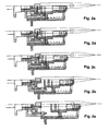
- Figure 1 is a schematic cross-sectional view according to a vertical plane of a device for picking up, handling and moving containers having at least one open end, according to a first preferred embodiment of the present invention.
- the device is used for picking up and handling blow-moulded bottles made of PET or PP.
- reference will be made indifferently to containers, bottles or objects to indicate the same objects on which the device according to the invention can be utilised.
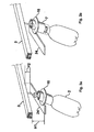
- the device for picking up, handling and moving objects which forms the subject of the present invention is designated, as a whole, by the reference number 1, and is suitable to fix an object 2 or, more particularly, a container 2, hereinafter referred to also as “bottle 2" - see Figures 3a and 3b, to a conveyor 3 of the type known as "endless traction element” or an overhead chain conveyor.
- the conveyor to which one or more picking-up devices 1 are to be applied may be a rope-and-button conveyor, a belt conveyor, a carriage conveyor, a platform conveyor, a slat conveyor, or an apron conveyor, and may also be a conveyor that stands on the floor or is located below floor level, or any other appropriate type of conveyor, to which the picking-up device 1, instead of hanging, may be fixed underneath after being rotated through 180° with respect to the position illustrated in Figure 1.
- the conveyor designated by the reference number 3 is generically a conveyor of any one of the aforementioned types.
- the device for picking up, handling and moving objects illustrated in Figure 1 comprises a rail or supporting guide made of section bar 4 obtained in general by bending, and, only in certain portions of the conveyor, by extrusion in order to ensure a higher stiffness and precision of positioning, as will be explained in greater detail in what follows.
- the device of Figure 1 is used in a plant (not shown) for the moulding and treatment of plastic bottles in order to convey the bottles from the blow-moulding unit to the stations downstream thereof, for example the coating or spray-coating stations, and from here to a possible drying oven, heat-treatment station, and/or a station for stacking or unloading the finished products.
- the device 1 for picking up, handling and moving objects shown in Figure 1 comprises a vertical shaft 5 inserted in a housing 6, on which there rotate, coaxially to the shaft 5, two rolling wheels (or bearings) 7a, 7b with vertical axis. Integral with the housing 6 is a horizontal shaft 8 on which there rotate two wheels (or bearings) 9a, 9b with horizontal axis.
- the shaft 5 can be fixed to a conveyor 3 in a wide range of ways; for example, it can be fixed in the middle of a chain element of a conveyor 3, at some distance from the wheels 7a, 7b, 9a, and 9b.
- the conveyor 3 can be of the type with just wheels with horizontal axis 9a, 9b or any other known conveyor of a suitable kind.
- the vertical shaft 5, supported by anti-friction bushings can turn about its own longitudinal axis with respect to the housing 6 and to the section bar 4, and can receive a rotational torque by means of the pinion gear 10 that is coaxial to it - for example the pinion gear 10 can be fixed on the shaft 5, either with an interference fit, or else with a slot-and-dowel, with an elastic pin 101 (see Figure 1b) or a taper pin.
- the pinion gear can be set in rotation, for example by a second drive chain which slides in the opposite direction to that of advance of the conveyor 3.
- the drive chain + pinion gear system 10 for example with a V-belt + pulley system, or else a plane belt + friction wheel system.
- the device 1 for picking up, handling and moving objects comprises picking-up means, usually called chuck, 20 suitable to grip and withhold the container 2 from inside the open end 200 (in the example shown, the picking-up means grip the bottle 2 from inside its neck 200 - Figure 3), and further comprises a protective sliding sleeve 7 suitable to cover and protect a predetermined portion of the object or container in the proximity of the open end 200 of the container 2, and is characterised in that the actuation for picking up or releasing the object 2 by the picking-up and withholding means 20 is independent of the movements of sliding of the sleeve 7 with respect to the ensemble of the device 1 for picking up, handling and moving objects.
- picking-up means usually called chuck
- a flange 11A having a slotted outer edge 11C which is complementary to the internal slotted section 40 of the sliding sleeve 7, with which it engages in such a way that it can slide therein longitudinally, transmitting driving torque parallel to the axis of rotation of the shaft 5 - the slotted coupling can be replaced by other modes of connection that enable vertical sliding with the transmission of a torque -. That is, the slotted external edge 11C constitutes a slide guide, on which the sleeve 7 slides.
- the picking-up means 20 in the preferred embodiment of Figure 1 consists of a radially expandable ring of elastic, or anyway deformable, fingers, extensions or prolongation 11B - made preferably of an injectable technopolymer with sufficient wear resistance, and resistance to temperature and chemical agents -, which rest, in a position corresponding to an internal groove ( Figure 1a), on an annular spring 21 set inside the aforesaid ring and positioned roughly perpendicular to the longitudinal axis of the ring.
- the annular spring 21 enables the ring of elastic prolongations 11B to expand or contract with an easily controllable radial elasticity (chiefly dependent upon the elastic characteristics of the wire of the spring and of its positioning along the axis of the ring), and enables solution of the problems of fatigue failure which elastic elements made of plastic material presented in the past.
- the thickness and shape of the elastic prolongations are adapted to the container that is to be conveyed, in order to support it more or less rigidly according to the process specifications (for example, speed, angular velocity, format of the container or preform, weight of the container or preform, design of the thread, temperature, etc.).
- the injectable polymer of which the ring of the elastic prolongations 11 B is made of, is polyvinylidene fluoride (PVDF) or another fluorine polymer or copolymer; the use of PVDF in carrying out the chuck 20 provides good friction forces with the bottleneck to be grasped; as further advantages, in this applications PVDF provides a good resistance to relatively high temperatures, around 100° to 120°C and wear, or erosion, resistance.
- PVDF polyvinylidene fluoride
- the ball-type press-block coupling is completed by a tubular element 12 ( Figure 1) the bottom end of which has internally a re-entrant surface shaped like the frustum of a cone.
- Preferably - but not necessarily - three balls 23 are housed inside the through holes in the vertical wall of the intermediate element 11.
- the balls jam in an annular groove 30 ( Figure 1a) or in a series of recesses suitable to transfer the moment generated by the rotation, made on the male part of the press-block coupling.
- the balls 23 are pushed towards the inside by the re-entrant surface shaped like a truncated cone (or by another system based on an inclined plane) since the tubular element 12 is pushed upwards by a first spring 13.
- the picking-up means 20 can be rapidly slid out by pushing the tubular element 12 downwards.
- the chuck 20 in Figure 1 are made hollow with an internal through hole through which an electrode 17 for electrostatic coating, the nozzle of a filler, or other elements which are to enter the bottle 2, can pass and come out.
- the sliding sleeve is constantly pressed downwards by a second spring 14 compressed between a bottom internal projection of the sleeve and the sliding flange 11A with slotted edge, and it is prevented from sliding out by an annular plug 15, which is snap-fitted into the top part of the sliding sleeve 7 and which bears upon the slotted flange when the device 1 for picking up, handling and moving objects is not gripping any bottle 2 and is empty.
- Raising of the sliding sleeve 7 can be controlled, for example, by a cam-type actuator made by providing on the sleeve a flange 16, which, during horizontal advance of the device 1, can be raised sliding on a pair of plane bars 24, which are also preferably made of technopolymers with an appropriate wear resistance and a low coefficient of sliding friction, for example, polyimide or polyphenyl resins, such as polyetherimide (PEI) or polyvinylidene fluoride (PVD), according to systems in themselves already known ( Figures 3a and 3b).
- the bar 24 is inclined with respect to the horizontal, the rail 3 is horizontal, and H1 is greater than H2.
- both the sliding sleeve 7 and the bars 24 - which are on the fixed supporting frame of the conveyor - of the cam-type actuation are made of appropriate technopolymers, which are sufficiently resistant to wear and which have low coefficients of sliding friction.
- a device 1 for picking up, handling and moving objects provided with the sliding sleeve 7, the annular plug 15 and the chuck 20 made of plastic material, can be injection-moulded at a low cost, has a very small weight and inertia, and the vibrations during a possible fast rotation of the bottle are such that the entire conveyor is subjected to less stress.
- the above three plastic components, which in the device 1 are the ones most subject to wear during operation, can be quickly replaced in a single operation, thanks to the ball-type press-block coupling, during extraordinary maintenance. Since In a plant for the production of bottles by blow-moulding, the devices 1 for picking up, handling and moving objects frequently number some hundreds, if not thousands, the overall saving is all the more evident.
- intermediate element 11 and the tubular element 12 are preferably made of metal.
- a bottle 2, or a generic container 2 having an open end 200 is pushed upwards against the ring of elastic extensions or prolongations 11 B into a loading station, in a known way.
- the ring of prolongations is driven into the neck 200 of the bottle 2 and, by friction, blocks the bottle 2 axially as well as preventing it from rotating.
- the second spring 14 keeps the sliding sleeve 7 pressed so that the latter bears upon one part of the bottle (for example, the collar or the tear-seal flange - Figure 5), in such a way as to isolate the neck 200 and obtain, as far as possible, a seal with respect to the outside environment, also depending upon the presence of other solution - if any - such as providing a seal on the annular ring of the sleeve which comes to bear upon the bottle 2.
- the shape, diameter, and travel of the sleeve 7 are designed according to the shape of the bottle or container and of the part of the bottle or container which the sleeve, when lowered, must isolate and protect from the outside environment.
- the sliding sleeve 7 also constitutes an additional protection and isolation - in combination with the picking-up means 20, which might occasionally be faulty - of the internal cavity of the bottle 2 not only against paint and solvent, but also against other external contaminants, such as lubricants.
- the bottle 2, produced, for instance, by blow-moulding, or by any other suitable technique, can thus be transported on an automatic conveyor 3 through the various processing stations downstream of the moulding station.
- the moulded bottle may pass through an HVLP spray-coating or electrostatic-coating station, for example for a colouring treatment or a treatment of impermeabilization to CO 2 or to molecular oxygen, as in the case of bottles for effervescent beverages, fruit juice or beer, or in any case beverages that are sensitive to attack by oxygen and to loss of CO 2 , without the region covered by the sliding sleeve for instance, the region of the neck and of the thread of the bottle, getting coated.
- the wheels 7A, 7B, 9A, 9B of the devices 1 are caused to slide within a precision-manufactured section bar 4, leaving an amount of play, between the wheels and the sectional strips 4, smaller than in the remaining stretches of the conveyor. This reduces the horizontal deflection of the device 1 under the thrust that the second drive chain exerts on the pinion gear 10.
- FIGs 4 and 5 are schematic illustrations of a second preferred embodiment of a device for picking up, handling and moving objects according to the present invention, in which the sliding sleeve 70, the springs 140 and 130, the tubular element 120, the intermediate element 110, the picking-up means 60, and the annular plug 150 correspond to, and have similar modes of operation as, respectively, the items designated by 7, 14, 13, 12, 11, 20 and 15 of Figure 1, previously described, whilst the shaft 50 for fixing to the conveying chain cannot rotate about its own axis, and the sleeve 70 + picking-up means 60 system can rotate on a vertical axis thanks to the bushings 180 and 190 set between the intermediate element 110 and the two elements 185 and 195, which are fixed with respect to the shaft 50.
- the sliding sleeve 70 can be set in rotation by a pulley, belt or cable which slides in a direction opposite to that of advance of the device 1 along the conveyor 3 and which grips inside the seat 170 made on the double flange similar to the flange 16 of Figures 3a and 3b. Also the double flange has the function of raising the sleeve 70 by means of an extemal-cam system 24, as illustrated in Figures 3a and 3b.
- the thickness and shape of the elastic extensions are adapted to the container that has to be conveyed, in order to support it more or less rigidly according to the process specifications, for example, conveying speed, angular velocity, format of the container or preform, weight of the container or preform, design of the thread, temperature, etc.
- the vertical shaft 5 may be either rotating or fixed, and may be positioned either in the vicinity of or at a distance from the wheels of the chain of the conveyor.
- the device 1 for picking up, handling and moving objects can be used for handling an extremely wide range of objects, including semi-finished products, such as preforms or parisons for blow-moulding;
- the flange 16 can be modified and replaced by one or more segments of flange or by an appropriate radial projection of the sliding sleeve 7, designed to raise the latter, sliding on an external cam;
- the annular spring 21 can be replaced generally with other radially resilient elements;
- the first male element 22 ( Figure 1a) integral with the picking-up means 20 can also be a metal insert around which the plastic body of the picking-up means 20 are co-moulded; further modifications are anyway possible.
Landscapes
- Engineering & Computer Science (AREA)
- Mechanical Engineering (AREA)
- Manufacturing & Machinery (AREA)
- Specific Conveyance Elements (AREA)
- Chain Conveyers (AREA)
- Control And Other Processes For Unpacking Of Materials (AREA)
- Manipulator (AREA)
- Blow-Moulding Or Thermoforming Of Plastics Or The Like (AREA)
Claims (16)
- Gerät (1) zum Halten von Produkten (2), die wenigstens ein offenes Ende (200) aufweisen, umfassend ein Aufnahmemittel (20), das geeignet ist das Produkt von der Innenseite des offenen Endes (200) her zu greifen und festzuhalten, weiter umfassend eine verschiebbare Schutzhülse (7, 70), mit der ein vorgegebener Abschnitt des Produkts (2) im Bereich des offenen Endes (200) abgedeckt und geschützt werden kann, dadurch gekennzeichnet, dass ein Mittel (24) vorhanden ist, um die genannte Schutzhülse (7, 70) zwischen einer ersten Position, in der der genannte vorgegebene Abschnitt des Produkts (2) im Bereich des offenen Endes nicht abgedeckt ist, und einer zweiten Position, in der der genannte vorgegebene Abschnitt des Produkts (2) im Bereich des offenen Endes abgedeckt ist, hin und her zu schieben, und dadurch gekennzeichnet, dass ein Antriebsmittel für das genannte Aufnahmemittel (20) vorhanden ist, wobei das genannte Antriebsmittel unabhängig von dem genannten Mittel zum Verschieben der genannten Schutzhülse ist.
- Gerät zum Halten von Produkten gemäß Anspruch 1, wobei die genannten Produkte einen Bundring oder einen Flansch zum Aufreißen des Siegels aufweisen und der genannte vorgegebene mit der Schutzhülse (7, 70) zu schützende Abschnitt wenigstens einen Teil der Seiten des genannten Halses bis zu dem genannten Bundring oder Flansch hinunter umfasst.
- Gerät gemäß Anspruch 1, wobei das Gerät weiter eine Gleitführung (11 C) umfasst, auf der die Schutzhülse gleiten kann und relativ zu der das Aufnahmemittel (20) eine feste Lage einnimmt.
- Gerät gemäß Anspruch 3 wobei die Schutzhülse (7, 70) wenigstens einen radialen Vorsprung 16 aufweist, mit dem die Gleitbewegung der Hülse (7, 70) über ein Nockenbetätigungssystem (24) gesteuert werden kann.
- Gerät gemäß Anspruch 3, wobei das Aufnahmemittel (20) auf seiner Außenseite einen in radialer Richtung dehnbaren Ring von elastischen und/oder deformierbaren Verlängerungen (11 B) aufweist.
- Gerät gemäß Anspruch 5, wobei die elastischen und/oder deformierbaren Verlängerungen (11B) auf einem in radialer Richtung elastischen Element (21) ruhen, das sich innerhalb des Rings elastischer und/oder deformierbarer Verlängerungen (11 B) befindet und relativ zu dem Ring selbst in radialer Richtung deformiert werden kann.
- Gerät gemäß einem oder mehreren der vorstehenden Ansprüche, wobei ein Mittel zur Bewegungsübertragung (10, 170) vorhanden ist, das geeignet ist das Aufnahmemittel (20) in Rotation zu versetzen, wobei das Mittel zur Bewegungsübertragung eine der folgenden Vorrichtungen ist: ein Zahntriebwerk, eine riemengetriebene Rolle oder ein Reibrad.
- Gerät gemäß Anspruch 1, wobei das Aufnahmemittel (20) einen ersten Sitz (22) für eine Druckblockkupplung umfasst, um das Aufnahmemittel (20) an das gesamte Gerät (1) zu koppeln.
- Gerät gemäß Anspruch 8, wobei ein Zwischenelement (11, 110) vorhanden ist, das seinerseits Folgendes umfasst: den zweiten Sitz zum Aufnehmen der Druckblockkupplung für das Aufnahmemittel (20), ein im Wesentlichen rohrförmiges Element (12, 120), das über dem Zwischenelement (11, 110) verschoben werden kann und durch eine Feder (13, 130) gedrückt wird, sowie eine oder mehrere geneigte Flächen oder geneigte Ebenen, die die Kugel oder die Kugeln (23) der Druckblockkupplung zusammendrücken können, wobei die gleitende Hülse (7, 70) auf einer oder um eine Außenfläche des rohrförmigen Elements (12, 120) gleiten kann.
- Gerät gemäß Anspruch 1, wobei weiter ein vertikales Verbindungselement (5, 50) vorhanden ist, das mit einem oder mehreren Rädern bzw. Rollen (7A, 7B; 9A, 9B) verbunden ist, die in einer tragenden Führung (4) gleiten können.
- Gerät gemäß Anspruch 10, wobei das vertikale Verbindungselement (5, 50) in Wesentlichen aus einem vertikalen Verbindungsschaft besteht, um den sich wenigstens ein Paar Räder oder Rollen (7A, 7B) um eine vertikale Achse dreht.
- Gerät gemäß Anspruch 11, wobei sich der vertikale Verbindungsschaft (5) um eine vertikale Achse in einem Gehäuse (6) drehen kann, auf dem sich das wenigstens eine Paar Räder oder Rollen (7A, 7B) koaxial mit dem Schaft (5) drehen kann.
- Gerät gemäß einem oder mehreren der vorstehenden Ansprüche, wobei das genannte Aufnahmemittel (20) aus einem formbaren Kunststoffmaterial besteht.
- Gerät gemäß Anspruch 13, wobei das genannte formbare Kunststoffmaterial Polyvinylidenfluorid und/oder Fluorpolymere und/oder Fluorcopolymere umfasst.
- Verfahren zum Manipulieren und Bewegen von Produkten (2), beispielsweise Flaschen oder anderen Behältern und Vorformlingen für das Druckluftformen, die wenigstens ein offenen Ende (200) und einen Hals aufweisen, wobei das genannte Verfahren mittels eines Geräts gemäß einem der Ansprüche 1 bis 5 durchgeführt wird und die folgenden Schritte umfasst:Greifen und Festhalten des Produkts (2) von der Innenseite des offenen Endes (200) her mit dem Aufnahmemittel (20), das weiter eine verschiebbare Schutzhülse (7) umfasst, die einen vorgegebenen Anschnitt des Produkts (2) im Bereich des offenen Endes (200) abdecken und schützen kann, wobei der genannte vorgegebene zu schützende Abschnitt wenigstens einen Teil der Seiten des genannten Halses umfasst und wobei das genannte Aufnahmemittel (20) durch einen Kreisförderer (3) mit einem Zugelement oder mit einer Förderband befördert wird;Bewegen des von dem Aufnahmemittel (20) festgehaltenen Produkts (2) durch eine vorgegebene Abfolge von Verarbeitungsstationen, wobei der vorgegebene Abschnitt des Produkts (2) im Bereich des offenen Endes (200) geschützt wird, indem wenigstens ein Teil der Seiten des Halses von der verschiebbaren Hülse (7) verdeckt ist;Freigeben des vorgegebenen Abschnitts des Produkts (2) im Bereich des offenen Endes (200) oder wenigstens eines Teils der Seiten des genannten Halses, wobei das Produkt weiter im offenen Ende (200) durch das Aufnahmemittel (20) festgehalten wird;Abnehmen des Produkts (2) von dem Aufnahmemittel (20) durch ein weiteres außerhalb des Aufnahmemittels (20) befindliches Aufnahmemittel.
- Verfahren gemäß Anspruch 15, wobei das Produkt (2) durch Greifen des offenen Endes (200) mit mechanischen Greifern von dem Aufnahmemittel (20) abgenommen wird.
Applications Claiming Priority (3)
| Application Number | Priority Date | Filing Date | Title |
|---|---|---|---|
| ITMI20010387 | 2001-02-26 | ||
| IT2001MI000387A ITMI20010387A1 (it) | 2001-02-26 | 2001-02-26 | Dispositivo e metodo per la presa e la movimentazione di oggetti |
| PCT/EP2002/001949 WO2002068300A1 (en) | 2001-02-26 | 2002-02-25 | Device and method for picking up, handling and moving objects |
Publications (2)
| Publication Number | Publication Date |
|---|---|
| EP1363846A1 EP1363846A1 (de) | 2003-11-26 |
| EP1363846B1 true EP1363846B1 (de) | 2005-10-12 |
Family
ID=11447018
Family Applications (1)
| Application Number | Title | Priority Date | Filing Date |
|---|---|---|---|
| EP02722130A Expired - Lifetime EP1363846B1 (de) | 2001-02-26 | 2002-02-25 | Verfahren und gerät zum aufnehmen, manipulieren und bewegen von produkten |
Country Status (9)
| Country | Link |
|---|---|
| US (1) | US7025193B2 (de) |
| EP (1) | EP1363846B1 (de) |
| JP (1) | JP4129398B2 (de) |
| CN (1) | CN1238230C (de) |
| CA (1) | CA2439411C (de) |
| DE (1) | DE60206601T2 (de) |
| IT (1) | ITMI20010387A1 (de) |
| RU (1) | RU2297380C2 (de) |
| WO (1) | WO2002068300A1 (de) |
Families Citing this family (15)
| Publication number | Priority date | Publication date | Assignee | Title |
|---|---|---|---|---|
| DE102005011804B4 (de) | 2005-03-15 | 2021-12-30 | Khs Corpoplast Gmbh | Verfahren und Vorrichtung zur Blasformung von Behältern |
| ITRM20060277A1 (it) * | 2006-05-24 | 2007-11-25 | Sipa Societa Industrializzazio | Impianto e processo di verniciatura di contenitori |
| DE102007037400A1 (de) | 2007-08-08 | 2009-02-12 | Krones Ag | Blasmaschine für Behälter und Dornhalter |
| US7473093B1 (en) * | 2007-09-28 | 2009-01-06 | Husky Injection Molding Systems Ltd. | Molded article picker |
| WO2009144664A2 (en) * | 2008-05-28 | 2009-12-03 | Sacmi Cooperativa Meccanici Imola Societa' Cooperativa | System for blowing plastic containers, specifically bottles. |
| IT1390890B1 (it) * | 2008-07-18 | 2011-10-19 | S I P A Societa' Ind Progettazione E Automazione S P A | Impianto di convogliamento di contenitori in materiale plastico |
| FR2942620B1 (fr) * | 2009-02-27 | 2011-03-25 | Sidel Participations | Dispositif de prehension d'un corps creux par son col |
| US8511730B2 (en) | 2011-11-18 | 2013-08-20 | The Procter & Gamble Company | Apparatus and method for engaging and handling articles of manufacture |
| DE102014212215A1 (de) * | 2014-06-25 | 2015-12-31 | Robert Bosch Gmbh | Greifeinheit zum Greifen und Halten von Behältnissen, insbesondere pharmazeutischen Behältnissen |
| ITUA20162626A1 (it) * | 2016-04-15 | 2017-10-15 | Sipa Progettazione Automaz | Sistema di trasferimento per contenitori |
| CN109132459B (zh) * | 2018-10-29 | 2024-04-05 | 长沙开元仪器有限公司 | 一种用于煤样瓶的进瓶装置 |
| EP4628278A3 (de) * | 2019-04-26 | 2026-04-01 | Rodney Laible | Verfahren zur herstellung eines behältereinsatzes zur verwendung in einem abgabesystem mit geschlossenem kreislauf |
| CN110510334B (zh) * | 2019-08-02 | 2024-11-01 | 珠海市金同农产品有限公司 | 一种鸡鸭升降送给装置 |
| DE102021121521A1 (de) * | 2021-08-19 | 2023-02-23 | Ulf Reinhardt | Stiftofen zum Herstellen von Behältern und Verfahren |
| FR3131581B1 (fr) * | 2022-01-03 | 2024-01-05 | Pochet Du Courval | Poste de chargement ou de déchargement d’objets creux en verre comprenant un système d’actionnement magnétique |
Family Cites Families (7)
| Publication number | Priority date | Publication date | Assignee | Title |
|---|---|---|---|---|
| US3945486A (en) * | 1974-10-15 | 1976-03-23 | Glass Containers Corporation | Container supporting and transporting device |
| US4082175A (en) * | 1977-05-17 | 1978-04-04 | Cincinnati Milacron Inc. | Conveyor combined with coupling |
| US4086999A (en) * | 1976-03-18 | 1978-05-02 | Cincinnati Milacron Inc. | Conveyor combined with coupling for handling workpiece |
| US4572355A (en) * | 1984-10-03 | 1986-02-25 | Sewell Plastics, Inc. | Coupling assembly |
| DE3908345C1 (en) * | 1989-03-15 | 1991-01-03 | Bekum Maschinenfabriken Gmbh, 1000 Berlin, De | Apparatus for blow-moulding prefabricated parisons |
| US5769476A (en) * | 1996-09-16 | 1998-06-23 | Feco Engineered Systems Ltd. | Apparatus and method for handling and processing articles |
| DE19922873A1 (de) * | 1999-05-19 | 2000-11-23 | Krones Ag | Vorrichtung zum Einbringen und/oder Ausbringen von Behältern |
-
2001
- 2001-02-26 IT IT2001MI000387A patent/ITMI20010387A1/it unknown
-
2002
- 2002-02-25 DE DE60206601T patent/DE60206601T2/de not_active Expired - Lifetime
- 2002-02-25 EP EP02722130A patent/EP1363846B1/de not_active Expired - Lifetime
- 2002-02-25 JP JP2002567629A patent/JP4129398B2/ja not_active Expired - Fee Related
- 2002-02-25 WO PCT/EP2002/001949 patent/WO2002068300A1/en not_active Ceased
- 2002-02-25 RU RU2003128868/11A patent/RU2297380C2/ru not_active IP Right Cessation
- 2002-02-25 CA CA2439411A patent/CA2439411C/en not_active Expired - Fee Related
- 2002-02-25 US US10/469,022 patent/US7025193B2/en not_active Expired - Fee Related
- 2002-02-25 CN CN02805578.0A patent/CN1238230C/zh not_active Expired - Fee Related
Also Published As
| Publication number | Publication date |
|---|---|
| DE60206601D1 (de) | 2006-02-23 |
| US7025193B2 (en) | 2006-04-11 |
| CN1238230C (zh) | 2006-01-25 |
| JP2004524245A (ja) | 2004-08-12 |
| RU2297380C2 (ru) | 2007-04-20 |
| WO2002068300A1 (en) | 2002-09-06 |
| RU2003128868A (ru) | 2005-02-10 |
| US20040134761A1 (en) | 2004-07-15 |
| CN1498188A (zh) | 2004-05-19 |
| EP1363846A1 (de) | 2003-11-26 |
| ITMI20010387A1 (it) | 2002-08-26 |
| CA2439411A1 (en) | 2002-09-06 |
| DE60206601T2 (de) | 2006-08-24 |
| JP4129398B2 (ja) | 2008-08-06 |
| CA2439411C (en) | 2010-09-07 |
Similar Documents
| Publication | Publication Date | Title |
|---|---|---|
| US7025193B2 (en) | Device and method for picking up, handling and moving objects | |
| KR101017440B1 (ko) | 블로우성형장치 | |
| CN1898137B (zh) | 型坯供应系统-尤其是用于容器吹塑机且带有定位不正型坯的逐出装置 | |
| KR101465641B1 (ko) | 물품 반송 장치 | |
| CN102431150B (zh) | 传送预制件的传送设备 | |
| US8640860B2 (en) | Device for gripping a blow-moulding container preform | |
| EP2671704B1 (de) | System zur Übergabe und Beabstandung von Objekte zwischen operativen Stationen | |
| EP0875470B1 (de) | Förderkettenvorrichtung | |
| CA2401286C (en) | Conveying apparatus for open containers | |
| US6575305B1 (en) | Arrangement for identifying and removing associated preforms from a continuous transfer line | |
| MX2010012977A (es) | Sistema para el soplado de envases de plastico, especificamente botellas. | |
| US7185753B2 (en) | Shuttle conveyor | |
| US20210371209A1 (en) | Method And System for Changing Article Pitch | |
| US20100193325A1 (en) | Method of conveying preforms and high speed device for tipping preforms | |
| JP2003500266A (ja) | 容器のブロー成形設備でブランクを搬送するシステム | |
| WO1995029860A1 (en) | Container transfer system for coating line | |
| KR102516341B1 (ko) | 용기 이송용 가변 그리퍼장치 | |
| US20030034231A1 (en) | Preform carrier | |
| US7337894B2 (en) | Conveyer for high temperature environment | |
| WO2019202447A1 (en) | Device for gripping containers | |
| EP1055619A1 (de) | Modulare Vorrichtung zum Kuppeln und Antreiben von freilaufenden Rollen welche Transport- und Lagerebenen bilden | |
| WO1998016367A2 (de) | Vorrichtung zur halterung von vorformlingen sowie blasmaschine zur formung von behältern | |
| CN106794942A (zh) | 成形品供给装置 | |
| US7431556B2 (en) | Stacking device for hollow stackable objects on exit from a rotating high-speed production machine | |
| EP4382278B1 (de) | Ein greifer für behältern oder vorformlinge |
Legal Events
| Date | Code | Title | Description |
|---|---|---|---|
| PUAI | Public reference made under article 153(3) epc to a published international application that has entered the european phase |
Free format text: ORIGINAL CODE: 0009012 |
|
| 17P | Request for examination filed |
Effective date: 20030925 |
|
| AK | Designated contracting states |
Kind code of ref document: A1 Designated state(s): AT BE CH CY DE DK ES FI FR GB GR IE IT LI LU MC NL PT SE TR |
|
| AX | Request for extension of the european patent |
Extension state: AL LT LV MK RO SI |
|
| RIN1 | Information on inventor provided before grant (corrected) |
Inventor name: ARMELLIN, ALBERTO Inventor name: LEONARDI, MARCO Inventor name: SARAN, ANDREA Inventor name: ZOPPAS, MATTEO Inventor name: TAMAGNONE, PAOLA |
|
| 17Q | First examination report despatched |
Effective date: 20040621 |
|
| GRAP | Despatch of communication of intention to grant a patent |
Free format text: ORIGINAL CODE: EPIDOSNIGR1 |
|
| RBV | Designated contracting states (corrected) |
Designated state(s): BE DE FR GB IT NL |
|
| RIN1 | Information on inventor provided before grant (corrected) |
Inventor name: LEONARDI, MARCO Inventor name: ZOPPAS, MATTEO Inventor name: SARAN, ANDREA Inventor name: TAMAGNONE, PAOLA Inventor name: ARMELLIN, ALBERTO |
|
| GRAS | Grant fee paid |
Free format text: ORIGINAL CODE: EPIDOSNIGR3 |
|
| GRAA | (expected) grant |
Free format text: ORIGINAL CODE: 0009210 |
|
| AK | Designated contracting states |
Kind code of ref document: B1 Designated state(s): BE DE FR GB IT NL |
|
| REG | Reference to a national code |
Ref country code: GB Ref legal event code: FG4D |
|
| REF | Corresponds to: |
Ref document number: 60206601 Country of ref document: DE Date of ref document: 20060223 Kind code of ref document: P |
|
| ET | Fr: translation filed | ||
| PLBE | No opposition filed within time limit |
Free format text: ORIGINAL CODE: 0009261 |
|
| STAA | Information on the status of an ep patent application or granted ep patent |
Free format text: STATUS: NO OPPOSITION FILED WITHIN TIME LIMIT |
|
| 26N | No opposition filed |
Effective date: 20060713 |
|
| PG25 | Lapsed in a contracting state [announced via postgrant information from national office to epo] |
Ref country code: IT Free format text: LAPSE BECAUSE OF NON-PAYMENT OF DUE FEES Effective date: 20070225 |
|
| PGRI | Patent reinstated in contracting state [announced from national office to epo] |
Ref country code: IT Effective date: 20110616 |
|
| REG | Reference to a national code |
Ref country code: FR Ref legal event code: PLFP Year of fee payment: 14 |
|
| PG25 | Lapsed in a contracting state [announced via postgrant information from national office to epo] |
Ref country code: BE Free format text: LAPSE BECAUSE OF NON-PAYMENT OF DUE FEES Effective date: 20150228 |
|
| PGRI | Patent reinstated in contracting state [announced from national office to epo] |
Ref country code: BE Effective date: 20150623 |
|
| REG | Reference to a national code |
Ref country code: FR Ref legal event code: PLFP Year of fee payment: 15 |
|
| REG | Reference to a national code |
Ref country code: FR Ref legal event code: PLFP Year of fee payment: 16 |
|
| REG | Reference to a national code |
Ref country code: FR Ref legal event code: PLFP Year of fee payment: 17 |
|
| PGFP | Annual fee paid to national office [announced via postgrant information from national office to epo] |
Ref country code: NL Payment date: 20180214 Year of fee payment: 17 |
|
| PGFP | Annual fee paid to national office [announced via postgrant information from national office to epo] |
Ref country code: GB Payment date: 20180221 Year of fee payment: 17 |
|
| PGFP | Annual fee paid to national office [announced via postgrant information from national office to epo] |
Ref country code: BE Payment date: 20180214 Year of fee payment: 17 |
|
| PGFP | Annual fee paid to national office [announced via postgrant information from national office to epo] |
Ref country code: FR Payment date: 20190225 Year of fee payment: 18 |
|
| REG | Reference to a national code |
Ref country code: NL Ref legal event code: MM Effective date: 20190301 |
|
| GBPC | Gb: european patent ceased through non-payment of renewal fee |
Effective date: 20190225 |
|
| REG | Reference to a national code |
Ref country code: BE Ref legal event code: MM Effective date: 20190228 |
|
| PG25 | Lapsed in a contracting state [announced via postgrant information from national office to epo] |
Ref country code: GB Free format text: LAPSE BECAUSE OF NON-PAYMENT OF DUE FEES Effective date: 20190225 Ref country code: NL Free format text: LAPSE BECAUSE OF NON-PAYMENT OF DUE FEES Effective date: 20190301 |
|
| PG25 | Lapsed in a contracting state [announced via postgrant information from national office to epo] |
Ref country code: BE Free format text: LAPSE BECAUSE OF NON-PAYMENT OF DUE FEES Effective date: 20190228 |
|
| PGFP | Annual fee paid to national office [announced via postgrant information from national office to epo] |
Ref country code: DE Payment date: 20200218 Year of fee payment: 19 |
|
| PG25 | Lapsed in a contracting state [announced via postgrant information from national office to epo] |
Ref country code: FR Free format text: LAPSE BECAUSE OF NON-PAYMENT OF DUE FEES Effective date: 20200229 |
|
| PGFP | Annual fee paid to national office [announced via postgrant information from national office to epo] |
Ref country code: IT Payment date: 20210224 Year of fee payment: 20 |
|
| REG | Reference to a national code |
Ref country code: DE Ref legal event code: R119 Ref document number: 60206601 Country of ref document: DE |
|
| PG25 | Lapsed in a contracting state [announced via postgrant information from national office to epo] |
Ref country code: DE Free format text: LAPSE BECAUSE OF NON-PAYMENT OF DUE FEES Effective date: 20210901 |