EP1363374A2 - Installationsgerät-Anschlusssystem - Google Patents
Installationsgerät-Anschlusssystem Download PDFInfo
- Publication number
- EP1363374A2 EP1363374A2 EP03009371A EP03009371A EP1363374A2 EP 1363374 A2 EP1363374 A2 EP 1363374A2 EP 03009371 A EP03009371 A EP 03009371A EP 03009371 A EP03009371 A EP 03009371A EP 1363374 A2 EP1363374 A2 EP 1363374A2
- Authority
- EP
- European Patent Office
- Prior art keywords
- connection
- screwless
- base
- terminals
- device connection
- Prior art date
- Legal status (The legal status is an assumption and is not a legal conclusion. Google has not performed a legal analysis and makes no representation as to the accuracy of the status listed.)
- Withdrawn
Links
Images


Classifications
-
- H—ELECTRICITY
- H01—ELECTRIC ELEMENTS
- H01R—ELECTRICALLY-CONDUCTIVE CONNECTIONS; STRUCTURAL ASSOCIATIONS OF A PLURALITY OF MUTUALLY-INSULATED ELECTRICAL CONNECTING ELEMENTS; COUPLING DEVICES; CURRENT COLLECTORS
- H01R24/00—Two-part coupling devices, or either of their cooperating parts, characterised by their overall structure
- H01R24/66—Two-part coupling devices, or either of their cooperating parts, characterised by their overall structure with pins, blades or analogous contacts and secured to apparatus or structure, e.g. to a wall
-
- H—ELECTRICITY
- H01—ELECTRIC ELEMENTS
- H01R—ELECTRICALLY-CONDUCTIVE CONNECTIONS; STRUCTURAL ASSOCIATIONS OF A PLURALITY OF MUTUALLY-INSULATED ELECTRICAL CONNECTING ELEMENTS; COUPLING DEVICES; CURRENT COLLECTORS
- H01R13/00—Details of coupling devices of the kinds covered by groups H01R12/70 or H01R24/00 - H01R33/00
- H01R13/62—Means for facilitating engagement or disengagement of coupling parts or for holding them in engagement
- H01R13/621—Bolt, set screw or screw clamp
- H01R13/6215—Bolt, set screw or screw clamp using one or more bolts
-
- H—ELECTRICITY
- H01—ELECTRIC ELEMENTS
- H01R—ELECTRICALLY-CONDUCTIVE CONNECTIONS; STRUCTURAL ASSOCIATIONS OF A PLURALITY OF MUTUALLY-INSULATED ELECTRICAL CONNECTING ELEMENTS; COUPLING DEVICES; CURRENT COLLECTORS
- H01R2103/00—Two poles
-
- H—ELECTRICITY
- H01—ELECTRIC ELEMENTS
- H01R—ELECTRICALLY-CONDUCTIVE CONNECTIONS; STRUCTURAL ASSOCIATIONS OF A PLURALITY OF MUTUALLY-INSULATED ELECTRICAL CONNECTING ELEMENTS; COUPLING DEVICES; CURRENT COLLECTORS
- H01R4/00—Electrically-conductive connections between two or more conductive members in direct contact, i.e. touching one another; Means for effecting or maintaining such contact; Electrically-conductive connections having two or more spaced connecting locations for conductors and using contact members penetrating insulation
- H01R4/28—Clamped connections, spring connections
- H01R4/48—Clamped connections, spring connections utilising a spring, clip, or other resilient member
- H01R4/4809—Clamped connections, spring connections utilising a spring, clip, or other resilient member using a leaf spring to bias the conductor toward the busbar
- H01R4/48185—Clamped connections, spring connections utilising a spring, clip, or other resilient member using a leaf spring to bias the conductor toward the busbar adapted for axial insertion of a wire end
- H01R4/4819—Clamped connections, spring connections utilising a spring, clip, or other resilient member using a leaf spring to bias the conductor toward the busbar adapted for axial insertion of a wire end the spring shape allowing insertion of the conductor end when the spring is unbiased
- H01R4/4821—Single-blade spring
-
- H—ELECTRICITY
- H01—ELECTRIC ELEMENTS
- H01R—ELECTRICALLY-CONDUCTIVE CONNECTIONS; STRUCTURAL ASSOCIATIONS OF A PLURALITY OF MUTUALLY-INSULATED ELECTRICAL CONNECTING ELEMENTS; COUPLING DEVICES; CURRENT COLLECTORS
- H01R4/00—Electrically-conductive connections between two or more conductive members in direct contact, i.e. touching one another; Means for effecting or maintaining such contact; Electrically-conductive connections having two or more spaced connecting locations for conductors and using contact members penetrating insulation
- H01R4/28—Clamped connections, spring connections
- H01R4/48—Clamped connections, spring connections utilising a spring, clip, or other resilient member
- H01R4/4809—Clamped connections, spring connections utilising a spring, clip, or other resilient member using a leaf spring to bias the conductor toward the busbar
- H01R4/4828—Spring-activating arrangements mounted on or integrally formed with the spring housing
- H01R4/483—Pivoting arrangements, e.g. lever pushing on the spring
-
- H—ELECTRICITY
- H01—ELECTRIC ELEMENTS
- H01R—ELECTRICALLY-CONDUCTIVE CONNECTIONS; STRUCTURAL ASSOCIATIONS OF A PLURALITY OF MUTUALLY-INSULATED ELECTRICAL CONNECTING ELEMENTS; COUPLING DEVICES; CURRENT COLLECTORS
- H01R4/00—Electrically-conductive connections between two or more conductive members in direct contact, i.e. touching one another; Means for effecting or maintaining such contact; Electrically-conductive connections having two or more spaced connecting locations for conductors and using contact members penetrating insulation
- H01R4/28—Clamped connections, spring connections
- H01R4/48—Clamped connections, spring connections utilising a spring, clip, or other resilient member
- H01R4/4809—Clamped connections, spring connections utilising a spring, clip, or other resilient member using a leaf spring to bias the conductor toward the busbar
- H01R4/484—Spring housing details
- H01R4/4842—Spring housing details the spring housing being provided with a single opening for insertion of a spring-activating tool
Definitions
- the invention relates to an installation device connection system.
- the invention can be used for example with motion detectors.
- the invention has for its object to provide an installation device connection system this is a problem-free and very simple mechanical and electrical assembly of the installation device.
- the network connection unit and device connection unit mechanically and electrically as separate units are designed so that the power supply unit is first mechanically assembled and can be electrically connected to the lines of the supply network. Subsequently the device connection unit is plugged onto the installed mains connection unit and mechanically connecting both units. Under use fewer and very inexpensive items will be a screwless connection technology both realized in the connection unit as well as in the device connection unit.
- the installation device can advantageously also be articulated, d. H. between Device connection unit or device base and other components of the installation device there may be movable joints in one or more axes his.
- the electrical connection between the device connection unit and these others Components are made using flexible device-internal cables. An assembly side It is not necessary to solder these internal lines to the device connection unit.
- the mains connection unit 1 shows a basic illustration of the components of a network connection unit shown.
- the mains connection unit 1 has a connection base 2 with three receiving chambers 3 for the loose use of three screwless terminals 10 on.
- the receiving chambers 3 On the face side, the receiving chambers 3 have insertion openings suitable for the cable entry 4 provided.
- Several locking pins 5 on the walls of the Receiving chambers are used to attach a protection against contact and fixation the cover 12 securing the connecting terminals.
- a mounting dome 6 is used to attach the installation device to the connection base 2.
- connection base 2 In the side walls and / or in the bottom of the connection base 2 can bores 7 (or predetermined breaking points) suitable for supplying the line (mains connection line) to break out such bores).
- the connector base 2 For attachment - in particular wall mounting - the connector base 2 are holes 8 in it Floor provided.
- a receiving chamber 9 is used to integrate a connection unit 17.
- several of these connection units can also be used in several Receiving chambers may be provided.
- the screwless terminals 10, which are also widely used for sockets have contact tulips 11 for the contacting of electrical in a generally known manner Plug contacts.
- the cover 12 is on the end face for cable entry suitable insertion openings 13 (corresponding to the insertion openings 4). Molded on the cover release buttons 14 are for releasing in the terminals 10 attached lines pressed.
- Locking holes 15 in the cover serve to receive the locking pins 5 of the connection base 2.
- Connector pin bores 16 serve to introduce those explained in more detail below Plug pins 28 in the contact tulips 11.
- Fig. 2 is a perspective view of one with screwless terminals and connection unit 17 equipped network connection unit 1.
- the cover 12 placed on the connection base 2 are covered by the Locking pin projecting locking holes 5 melted on the end, whereby locking end portions are formed to fix the cover.
- the Pin holes 16 are directly over the contact tulips of the terminals arranged.
- the mounting dome 6 and the release buttons are in the FIG 14 numbered.
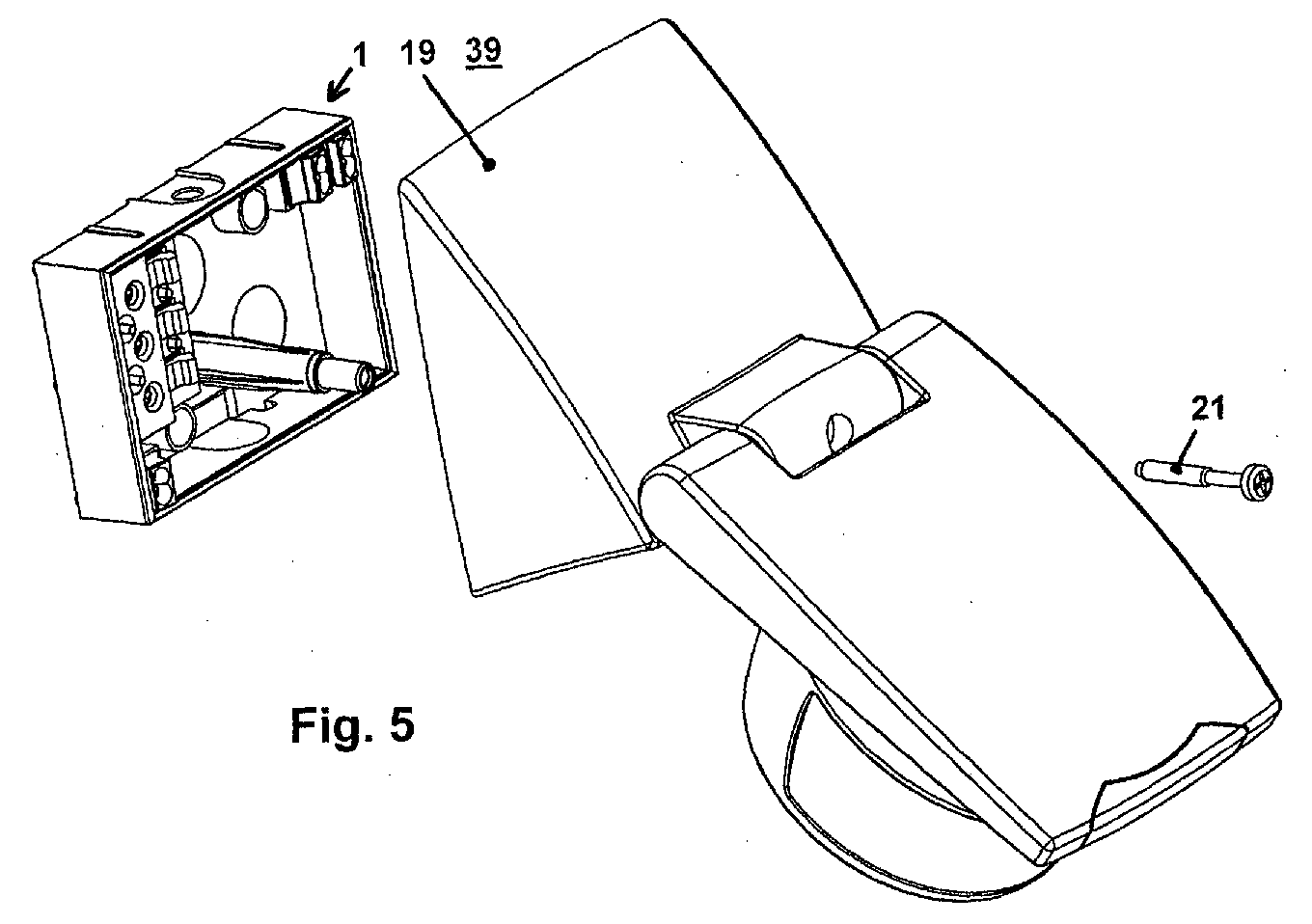
- the device connection unit 18 has a device base 19, which a fastening dome corresponding to the fastening dome 6 of the network connection unit 1 20, with a fastening screw for connecting the two fastening domes 21 engages in the fixing dome 6 through the fixing dome 20.
- Locking pin 22 of the device base 19 are used to attach a receptacle 23 and a cover 33 covering this receptacle.
- the receptacle 23 has three receiving chambers 24 for loose use in sockets frequently used screwless terminals 31. Such terminals are advantageous because of their mass production for sockets Can be obtained or manufactured inexpensively.
- screwless terminals 31 gives the possibility of being tinned inside the installation device to connect flexible cables electrically without screws and without soldering. They are on the front Receiving chambers 24 with insertion openings 25 suitable for cable entry Mistake.
- a plurality of locking bores 26 serve to push the locking pins through 22.
- Several locking pins 27 on the walls of the receiving chambers 24 of the receptacle 23 serve to fasten the cover 33.
- the screwless terminals 31 have contact tulips 32 through which preferably plug pins 28 designed as hollow rivets. These connector pins 28 are each provided at their first end with a locking collar 29, which after the device connection unit 18 has been completely equipped between the contact tulip 32 and bottom of the receptacle 23 is arranged, whereby a permanent locking of the Connector pins are made.
- the connector pins 28 each have one at their second end Cone section (taper) 30, which the insertion of the connector pins 28 in the Contact tulip 11 of a screwless terminal 10 of the power supply unit 1 facilitated.
- the cover 33 is on the end face with insertion openings suitable for cable entry 34 provided (corresponding to the insertion openings 25). Pin holes 35 in the cover 33 are used to carry out the above Plug pins 28. Locking holes 36 in the cover serve to receive the Locking pin 22 of the device base 19. Additional locking holes 37 in the Cover serve to receive the locking pin 27 of the receptacle 23. The fixation the cover 33 on the receptacle 23 and the fixation of the receptacle on Device base 19 is done by fusing the through the locking holes gripping locking pin. The cover 33 provides the fixation of the connector pins 28 assembled screwless terminals 31 securely.
- a screwless connection terminal has two insertion openings Plug in two lines. Since this is mostly with regard to the device connection unit is not required, the insertion openings 25, 34 can be arranged or formed in this way be that only a single insertion opening of a screwless terminal 31 is accessible. In this way, the factory assembly of the device-internal lines facilitated and in particular a faulty assembly (by electrically connecting two different lines to a single connection terminal) prevented.
- One with the device connection unit or with the device base is not numbered connecting component of the installation device (here motion detector).
- FIG. 4 is a perspective view of one with screwless terminals and connector pins 28 equipped device connection unit, wherein the installation device is designed as a motion detector 39.
- the installation device is designed as a motion detector 39.
- the locking pins 22, 27 are melted on the ends, as above explains what locking end portions are formed.
- Fig. 5 is a perspective view of a to be mounted on a power supply unit Motion detector 39 shown.
- the connector pins 28 can be coded in the Device connection unit may be arranged. Such coding is used, for example achieved if not all receiving chambers 24 with screwless terminals 31 and thus be equipped with connector pins 28.
- the receiving chambers 3 have screwless terminals 10 equipped. Accordingly, there are pin holes 35 and 16 only at the location of the receiving chambers equipped with connecting terminals. A faulty 180 ° rotated plugging of the device connection unit 18 on the power supply unit 1 is thus reliably prevented.
- the coding option explained above is dispensed with, it is also possible to according to an alternative embodiment to dispense with the receptacle 23 and directly in the base 19, the receiving chambers for the screwless terminals to provide, a cover closes these receiving chambers.
- the use of the additional receptacle 23 offers the advantage of differently designed ones and to fix coded receptacles 23 in device bases 19 of the same design.
- FIG. 6 is a side view of a motion detector attached to a power supply unit 1 39 shown with device base 19.
- the network connection unit 1 is on the site For example, attached to a wall and there electrically with the power lines connected to the supply network.
Landscapes
- Details Of Connecting Devices For Male And Female Coupling (AREA)
Abstract
Description
- Fig.1
- eine prinzipielle Darstellung der Komponenten einer Netzanschlußeinheit,
- Fig. 2
- eine perspektivische Ansicht einer bestückten Netzanschlußeinheit,
- Fig. 3
- eine prinzipielle Darstellung der Komponenten einer Geräteanschlußeinheit,
- Fig. 4
- eine perspektivische Ansicht einer bestückten Geräteanschlußeinheit,
- Fig. 5
- eine perspektivische Ansicht eines an einer Netzanschlußeinheit zu montierenden Bewegungsmelders,
- Fig. 6
- eine Seitenansicht eines an einer Netzanschlußeinheit befestigten Bewegungsmelders.
- eine Netzanschlußeinheit 1,
- eine Geräteanschlußeinheit 18 des Installationsgerätes, beispielsweise eines Bewegungsmelders 39.
Claims (12)
- Installationsgerät-Anschlußsystem mit zwei über Steckerstifte (28) elektrisch miteinander verbindbaren Hauptkomponenten, nämlicha) mit einer ortsseitig montierbaren und mit Netzleitungen verbindbaren Netzanschlußeinheit (1),b) mit einer mit geräteinternen Leitungen des Installationsgerätes verbindbaren Geräteanschlußeinheit (18),c) wobei die Netzanschlußeinheit (1) einen mit schraubenlosen Anschlußklemmen (10) bestückten Anschlußsockel (2) aufweist,d) wobei die Geräteanschlußeinheit (18) einen mit schraubenlosen Anschlußklemmen (31) bestückten Gerätesockel (19) aufweist,e) wobei die Steckerstifte (28) in Kontakttulpen (32) der schraubenlosen Anschlußklemmen (31) des Gerätesockels (19) fixiert sind undf) wobei die Steckerstifte (28) in Kontakttulpen (11) der schraubenlosen Anschlußklemmen (10) des Anschlußsockels (2) eingreifen.
- Installationsgerät-Anschlußsystem nach Anspruch 1, dadurch gekennzeichnet, daß der Anschlußsockel (2) Aufnahmekammern (3) für die schraubenlosen Anschlußklemmen (10) aufweist, welche mittels einer Abdeckung (12) abdeckbar sind, wobei diese Abdeckung Steckerstiftbohrungen (16) zum Einstecken der Steckerstifte (28) aufweist.
- Installationsgerät-Anschlußsystem nach Anspruch 2, dadurch gekennzeichnet, daß der Anschlußsockel (12) Arretierungszapfen (5) aufweist, welche durch Arretierungsbohrungen (15) der Abdeckung (12) greifen.
- Installationsgerät-Anschlußsystem nach Anspruch 1 oder 2, dadurch gekennzeichnet, daß die Abdeckung (12) Lösetasten (14) für die schraubenlosen Anschlußklemmen (10) aufweist.
- Installationsgerät-Anschlußsystem nach Anspruch 1, dadurch gekennzeichnet, daß der Gerätesockel (19) Aufnahmekammern (24) für die schraubenlosen Anschlußklemmen (31) aufweist, welche mittels einer Abdeckung (33) abdeckbar sind, wobei diese Abdeckung Steckerstiftbohrungen (35) zur Durchführung der Steckerstifte (28) aufweist.
- Installationsgerät-Anschlußsystem nach Anspruch 5, dadurch gekennzeichnet, daß der Gerätesockel (19) Arretierungszapfen (22) aufweist, welche durch Arretierungsbohrungen (36) der Abdeckung (33) greifen.
- Installationsgerät-Anschlußsystem nach Anspruch 5 oder 6, dadurch gekennzeichnet, daß die Abdeckung (33) zum Werkzeugeinsatz geeignete Bohrungen (38) zum Lösen von in die schraubenlosen Anschlußklemmen (31) eingesteckten Leitungen aufweist.
- Installationsgerät-Anschlußsystem nach einem der Ansprüche 5 bis 7, dadurch gekennzeichnet, daß eine eigenen Aufnahme (23) vorgesehen ist, welche die Aufnahmekammern (24) für schraubenlose Anschlußklemmen (31) aufweist und welche Arretierungsbohrungen (26) für den Durchgriff der Arretierungszapfen (2) des Gerätesockels (19) aufweist.
- Installationsgerät-Anschlußsystem nach einem der Ansprüche 5 bis 8, dadurch gekennzeichnet, daß Einstecköffnungen (25, 34) für das Einführen von Leitungen in schraubenlose Anschlußklemmen (31) derart vorgesehen sind, daß nur jeweils eine einzige Einführöffnung je Anschlußklemme zugänglich ist.
- Installationsgerät-Anschlußsystem nach einem der vorstehenden Ansprüche. dadurch gekennzeichnet, daß die Steckerstifte (28) in codierter Weise in der Geräteanschlußeinheit (18) angeordnet sind, so daß ein fehlerhaftes Aufstecken einer Geräteanschlußeinheit (18) auf eine Netzanschlußeinheit (1) oder das Aufstecken einer nicht passenden Geräteanschlußeinheit (18) nicht möglich ist.
- Installationsgerät-Anschlußsystem nach einem der vorstehenden Ansprüche, dadurch gekennzeichnet, daß ein Steckerstift (28) an seinem einen Ende einen Arretierungsbund (29) und an seinem anderen Ende einen Kegelabschnitt (30) aufweist.
- Installationsgerät-Anschlußsystem nach einem der vorstehenden Ansprüche, dadurch gekennzeichnet, daß die Befestigung zwischen Netzanschlußeinheit (1) und Geräteanschlußeinheit (18) über Befestigungsdome (6, 20) im Anschlußsockel (2) und im Gerätesockel (13) erfolgt.
Applications Claiming Priority (2)
| Application Number | Priority Date | Filing Date | Title |
|---|---|---|---|
| DE10221292A DE10221292B4 (de) | 2002-05-14 | 2002-05-14 | Installationsgerät-Anschlußsystem |
| DE10221292 | 2002-05-14 |
Publications (2)
| Publication Number | Publication Date |
|---|---|
| EP1363374A2 true EP1363374A2 (de) | 2003-11-19 |
| EP1363374A3 EP1363374A3 (de) | 2004-12-15 |
Family
ID=29265265
Family Applications (1)
| Application Number | Title | Priority Date | Filing Date |
|---|---|---|---|
| EP03009371A Withdrawn EP1363374A3 (de) | 2002-05-14 | 2003-04-25 | Installationsgerät-Anschlusssystem |
Country Status (2)
| Country | Link |
|---|---|
| EP (1) | EP1363374A3 (de) |
| DE (1) | DE10221292B4 (de) |
Families Citing this family (3)
| Publication number | Priority date | Publication date | Assignee | Title |
|---|---|---|---|---|
| DE102005036436B3 (de) * | 2005-08-03 | 2006-12-21 | Abb Patent Gmbh | Bewegungsmelder mit einem Haupt-Anschlussraum zwischen einem Montagesockel-Unterteil und einer Montagesockel-Abdeckung |
| DE102005036435B4 (de) | 2005-08-03 | 2007-06-28 | Abb Patent Gmbh | Bewegungsmelder mit Montagesockel-Unterteil und Montagesockel-Abdeckung |
| DE102007045869B3 (de) * | 2007-09-25 | 2008-08-21 | Albrecht Jung Gmbh & Co. Kg | Elektrisches/elektronisches Installationsgerät |
Family Cites Families (15)
| Publication number | Priority date | Publication date | Assignee | Title |
|---|---|---|---|---|
| DE3441671A1 (de) * | 1984-11-12 | 1986-05-15 | WAGO Verwaltungsgesellschaft mbH, 4950 Minden | Anschluss- und/oder durchfuehrungsklemme |
| DE3910514C2 (de) * | 1989-04-01 | 1998-07-02 | Merten Gmbh & Co Kg Geb | Infrarot-Bewegungsmelder |
| DE4003701C2 (de) * | 1990-02-05 | 1996-04-18 | Wago Verwaltungs Gmbh | Elektr. Anschlußklemme |
| DE4312778C3 (de) * | 1993-04-20 | 2001-10-25 | Vossloh Schwabe Gmbh | Elektrische Anschlußklemmeinrichtung |
| DE4336189C2 (de) * | 1993-10-23 | 2001-02-01 | Kleinhuis Hermann Gmbh | Geräteanschlußklemme |
| DE4412870A1 (de) * | 1994-04-14 | 1995-10-19 | Liebherr Hausgeraete | Elektrische Anschlußeinrichtung eines Kühl- und/oder Gefriergerätes |
| DE4413643C2 (de) * | 1994-04-20 | 1996-03-28 | Vossloh Schwabe Gmbh | Elektrische Anschluß- und Verbindungsklemme |
| DE29521473U1 (de) * | 1994-06-01 | 1997-06-26 | Saia-Burgess Electronics Ag, Murten | Elektrogerät |
| DE19508695B4 (de) * | 1995-03-02 | 2004-03-25 | Wago Verwaltungsgesellschaft Mbh | Trafoklemme |
| DE19610958C2 (de) * | 1996-03-20 | 1999-02-04 | Weidmueller Interface | Mehrpoliger Steckverbinder mit Zugfederanschlüssen |
| DE19617259A1 (de) * | 1996-04-18 | 1997-10-23 | Wago Verwaltungs Gmbh | Elektr. Klemme mit einem nach oben offenen Schneidklemmkontakt |
| DE19729014A1 (de) * | 1997-07-02 | 1999-01-07 | Wago Verwaltungs Gmbh | Elektronische Vorschaltgeräteklemme |
| DE19751705C2 (de) * | 1997-11-21 | 2000-11-09 | Jordan Paul Eltech | Verrasteter Einbaublock |
| DE20012352U1 (de) * | 2000-07-14 | 2000-09-14 | Phoenix Contact GmbH & Co. KG, 32825 Blomberg | Durchführungsklemme |
| DE10049751A1 (de) * | 2000-10-07 | 2002-04-25 | Aeg Hausgeraete Gmbh | Spannungsversorgung für Haushaltsgeräte |
-
2002
- 2002-05-14 DE DE10221292A patent/DE10221292B4/de not_active Expired - Fee Related
-
2003
- 2003-04-25 EP EP03009371A patent/EP1363374A3/de not_active Withdrawn
Also Published As
| Publication number | Publication date |
|---|---|
| EP1363374A3 (de) | 2004-12-15 |
| DE10221292A1 (de) | 2003-11-27 |
| DE10221292B4 (de) | 2006-09-14 |
Similar Documents
| Publication | Publication Date | Title |
|---|---|---|
| DE19716137C1 (de) | Modul zum Anschluß von Aktoren und/oder Sensoren | |
| EP1950836B1 (de) | Elektrische Anschlussklemme | |
| EP2351154B1 (de) | Reihenklemmenanordnung mit querverbindern und prüfsteckern | |
| DE102013114521A1 (de) | Türöffner mit elektrischem Anschlussblock | |
| EP2084784A2 (de) | Steckverbindung, insbesondere für sensor-/aktorleitungen | |
| DE202004011226U1 (de) | Einzelsteuergerät für Schildausbaugestelle | |
| DE102008025432A1 (de) | KLemmenanschlußblock | |
| DE10221292B4 (de) | Installationsgerät-Anschlußsystem | |
| EP3066720B1 (de) | Elektrischer verbinder mit einer mantelklemme | |
| EP3477791B1 (de) | Abgriffsteckverbinder | |
| DE102012111125B4 (de) | RJ45-Stecker und Steckverbinderanordnung mit Positionierungselement | |
| DE8111418U1 (de) | Anschlußverteiler | |
| WO2012031808A1 (de) | Verbindungssystem sowie aufnahmeeinheit für ein steuergerät | |
| EP2034568B1 (de) | Datentechnik-Anschlussdose | |
| DE202008000942U1 (de) | Elektrischer Steckverbinder | |
| WO2018234288A1 (de) | Signalvorrichtung und steckverbinder | |
| EP0328992A2 (de) | Elektrischer Steckverbinder | |
| EP1652274B1 (de) | Steckverbindungssystem mit integrierter verriegelung | |
| EP1039606B1 (de) | Vorrichtung zum elektrisch leitenden Verbinden von mindestens zwei elektrischen Geräten | |
| DE10331441A1 (de) | Kontakteinsatz zum Anschließen der Leiter eines mehradrigen Kabels und elektrisches Gerät | |
| EP1703593B1 (de) | Klemmtechnik für den Innenleiter einer Koaxialleitung zum Anschluss an eine Antennendose | |
| DE8109133U1 (de) | Anschlußklemme insbesondere zur Kontaktierung gedruckter Schaltungen | |
| DE10328497B4 (de) | Steckdosensockel einer elektrischen Steckdose | |
| DE102023129408A1 (de) | Anschlussadapter zum mechanischen Befestigen von elektrischen Steckverbindern verschiedener Bautypen | |
| DE102016119089B4 (de) | Elektronische Baugruppe |
Legal Events
| Date | Code | Title | Description |
|---|---|---|---|
| PUAI | Public reference made under article 153(3) epc to a published international application that has entered the european phase |
Free format text: ORIGINAL CODE: 0009012 |
|
| AK | Designated contracting states |
Kind code of ref document: A2 Designated state(s): AT BE BG CH CY CZ DE DK EE ES FI FR GB GR HU IE IT LI LU MC NL PT RO SE SI SK TR |
|
| AX | Request for extension of the european patent |
Extension state: AL LT LV MK |
|
| PUAL | Search report despatched |
Free format text: ORIGINAL CODE: 0009013 |
|
| AK | Designated contracting states |
Kind code of ref document: A3 Designated state(s): AT BE BG CH CY CZ DE DK EE ES FI FR GB GR HU IE IT LI LU MC NL PT RO SE SI SK TR |
|
| AX | Request for extension of the european patent |
Extension state: AL LT LV MK |
|
| RIC1 | Information provided on ipc code assigned before grant |
Ipc: 7H 01R 13/66 B Ipc: 7G 08B 25/06 B Ipc: 7H 01R 19/16 B Ipc: 7H 02G 3/00 A |
|
| 17P | Request for examination filed |
Effective date: 20050324 |
|
| AKX | Designation fees paid |
Designated state(s): AT BE CH DE ES LI NL |
|
| STAA | Information on the status of an ep patent application or granted ep patent |
Free format text: STATUS: THE APPLICATION IS DEEMED TO BE WITHDRAWN |
|
| 18D | Application deemed to be withdrawn |
Effective date: 20071103 |