EP1362952A1 - Blattbildungsvorrichtung - Google Patents
Blattbildungsvorrichtung Download PDFInfo
- Publication number
- EP1362952A1 EP1362952A1 EP03101322A EP03101322A EP1362952A1 EP 1362952 A1 EP1362952 A1 EP 1362952A1 EP 03101322 A EP03101322 A EP 03101322A EP 03101322 A EP03101322 A EP 03101322A EP 1362952 A1 EP1362952 A1 EP 1362952A1
- Authority
- EP
- European Patent Office
- Prior art keywords
- suction
- forming device
- suction box
- sheet forming
- roller
- Prior art date
- Legal status (The legal status is an assumption and is not a legal conclusion. Google has not performed a legal analysis and makes no representation as to the accuracy of the status listed.)
- Ceased
Links
- XLYOFNOQVPJJNP-UHFFFAOYSA-N water Substances O XLYOFNOQVPJJNP-UHFFFAOYSA-N 0.000 claims abstract description 9
- 229910010293 ceramic material Inorganic materials 0.000 claims abstract description 4
- 239000011111 cardboard Substances 0.000 claims description 15
- 239000011087 paperboard Substances 0.000 claims description 15
- 238000007789 sealing Methods 0.000 claims description 11
- 239000011358 absorbing material Substances 0.000 claims description 3
- 238000005299 abrasion Methods 0.000 description 2
- 230000015572 biosynthetic process Effects 0.000 description 2
- 238000004519 manufacturing process Methods 0.000 description 2
- 239000000919 ceramic Substances 0.000 description 1
- 230000006378 damage Effects 0.000 description 1
- 238000010790 dilution Methods 0.000 description 1
- 239000012895 dilution Substances 0.000 description 1
- 238000005516 engineering process Methods 0.000 description 1
- 239000000463 material Substances 0.000 description 1
- 239000000123 paper Substances 0.000 description 1
- 238000005096 rolling process Methods 0.000 description 1
Images


Classifications
-
- D—TEXTILES; PAPER
- D21—PAPER-MAKING; PRODUCTION OF CELLULOSE
- D21F—PAPER-MAKING MACHINES; METHODS OF PRODUCING PAPER THEREON
- D21F9/00—Complete machines for making continuous webs of paper
- D21F9/003—Complete machines for making continuous webs of paper of the twin-wire type
- D21F9/006—Complete machines for making continuous webs of paper of the twin-wire type paper or board consisting of two or more layers
-
- D—TEXTILES; PAPER
- D21—PAPER-MAKING; PRODUCTION OF CELLULOSE
- D21F—PAPER-MAKING MACHINES; METHODS OF PRODUCING PAPER THEREON
- D21F11/00—Processes for making continuous lengths of paper, or of cardboard, or of wet web for fibre board production, on paper-making machines
- D21F11/02—Processes for making continuous lengths of paper, or of cardboard, or of wet web for fibre board production, on paper-making machines of the Fourdrinier type
- D21F11/04—Processes for making continuous lengths of paper, or of cardboard, or of wet web for fibre board production, on paper-making machines of the Fourdrinier type paper or board consisting on two or more layers
Definitions
- the invention relates to a sheet forming device for producing a multilayer Paper or cardboard web with a sheet formation unit consisting of a primary sieve and a secondary sieve, the second layer of the multilayer Paper or cardboard web on a first by means of a rubber element Position of the primary screen, and the secondary screen in its course Deflection element for its deflection from a horizontal downward.
- the deflecting element is at least partially surrounded by a suction box, the suction box being seen through a first sealing element in the web running direction before the secondary screen runs onto the deflecting element and through a second sealing element in the web running direction seen after the secondary screen has run off from the deflection element in each case transversely to the web running direction against the secondary screen, and that at least one device with which the suction box is connected to at least one suction device comprising a suction pump and at least one suction nozzle with which this is in the suction box accumulated water can be removed are provided.
- This suction box ensures that the paper or cardboard web formed on the secondary wire is held in the area of the mentioned deflection over an extended distance due to the negative pressure present on the secondary wire and on the deflecting element and is thus guided securely. Skidding and possible destruction of the paper or cardboard web formed is effectively avoided.
- the sealing elements have wear parts made of ceramic on their outer surface Material. This is particularly important with regard to the service life of the secondary screen advantageous due to reduced abrasion. Furthermore, the stake causes of ceramic material no increased noise levels.
- the deflection element Acting scraper In the interior of the suction box there is also at least one on the deflection element Acting scraper provided so that the deflection elements are free of any Deposits and residues operated under optimal conditions can be.
- the deflecting element is a roller, in particular a screen suction roll or a forming roll.
- the roller can vary Use a closed surface or an open one, especially one have drilled and / or grooved surface
- the central support device within the roller provided on which the roller shell is supported.
- the central support device which is preferably a central yoke and at least one hydraulic supported punch with support member, points as a support member, for example a sliding shoe or a rolling device.
- the deflection element can also be a stationary suction shoe his.
- a suction shoe has long been known and has become well proven in many applications.
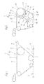
- FIG. 1 shows a sheet-forming device 1 according to the known prior art in a schematic side view.
- a sheet forming device 1 for producing a multilayer paper or cardboard web 2 comprises a sheet forming unit 1.1, consisting of a primary screen 3 and a secondary screen 4, which a second layer 5 of the multilayer paper or cardboard web 2 by means of a rubber element 6 on a first layer 7 of the Depends primary screen 3, and the secondary screen 4 has in its course a deflection element 8 for deflecting it from a horizontal H downwards.
- the sheet forming device 1 is associated with further devices and elements which are known to the person skilled in the art and which are not shown for the sake of simplicity.
- the web running directions of the screens 3, 4 are shown in all figures by means of arrows.
- FIG. 2 now shows a first sheet forming device 1 according to the invention, like the other figures in a schematic side view.
- the deflection element 8 is at least partially surrounded by a suction box 9, the suction box 9 being seen through a first sealing element 10 in the web running direction before the secondary screen 4 runs onto the deflection element 8 and through a second sealing element 11 in the web running direction after the secondary screen 4 has run out from the deflection element 8 is sealed transversely to the web running direction against the secondary wire 4.
- a device 12 with which the suction box 9 is connected to at least one suction device 14 comprising a suction pump 13, and a suction nozzle 15 with which the water accumulated in the suction box 9 can be removed are provided.
- the device 12 for the suction device 14 is the same as the suction nozzle 15 for water removal.
- the suction device 14 can be connected transversely to the web running direction as well as laterally on the suction box 9.
- the sealing elements 10, 11 advantageously wear parts 16 made of ceramic material on their outer surface.
- at least one scraper 18 acting on the deflection element 8 is provided in the interior 17 of the suction box 9, and a splash water protection 20 in a known design, for example in the form of a guide plate, is provided at the mouths of suction pipes 19 leading into the interior 17 of the suction box 9.
- the jacket 21 of the suction box 9 is advantageously covered with a cover 22 made of sound-absorbing material.
- the rubber element 6 is designed as a rubber roller 6.1.
- the deflection element 8, as shown in all the figures, is designed as a roller 8.1, in particular a screen suction roller or a forming roller. In the two Figures 1 and 2, this has a closed surface.
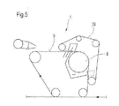
- FIGs 3, 4 and 5 show further advantageous embodiments of the invention Sheet forming device 1, with regard to the general Description of these figures will refer to the description of Figure 2.
- the roller 8.1 shown in Figure 3 has an open, in particular a drilled and / or grooved surface on and within the roller 8.1 is a central one Support device 23 is provided on which the roller shell 8.2 is supported.
- the central support device 23 has a slide shoe 25 as a support member 24, however, it can also have a roller device (not shown) as a support member 24.
- the sheet-forming device 1 of FIG. 3 furthermore has an only indicated upper sieve 26 together with an upper sieve suction box 27 (“D part”) for forming the second layer 5, which is opposed by 4 pressure strips 28 in the secondary sieve, which can be elastically attached, for example.
- the upper wire 26 is separated from the second layer 5 in the web running direction in front of or on the roller 8.1.
- the deflection element 8 can also be a stationary suction shoe.
- the rubber element also has 6 an embodiment of a rubber roller 6.1 Suction box 9.1 with features already mentioned.
- FIG. 5 shows an embodiment of the sheet forming device 1 similar to that of FIG. 3, but the top wire 26 wraps around the roller 8 and thus the top wire 26 is separated from the second layer 5 in the web running direction only after the roller 8.
- the top wire continues the second layer and places it on the primary wire, the headbox of the second layer then being directed in the direction of travel of the primary wire.
- the placement of the second layer on the primary screen can also be supported by means of at least one device, such as a suction device.
- An upper sieve suction box (“D part”) can also be arranged in the running direction in front of the deflection element in the upper sieve.
- the sheet forming device 1 of FIG. 5 merely represents a basic version for a wide variety of design options known to the person skilled in the art.
- the sheet forming device 1 shown in FIG. 6 has a secondary screen 4 which, in its course, has a deflection element 8 for deflecting it has a horizontal H down.
- the downward deflection lies there in a range from 15 ° to 75 °, preferably from 30 ° to 60 °, and the deflecting element 8 is at least partially of a suction box 9 according to the invention surround.
- the first layer 7 of the multilayer paper or cardboard web 2 is by means of a gap former, which is designed, for example, as a "DuoFormer Base", educated.
- a gap former of the "DuoFormer Base” type is, for example, from the German patent application DE 198 03 591 A1 (PB10656 DE) of the applicant known.
- the sheet forming device 1 of Figure 7 is used to produce a three-layer Paper or cardboard web 2.1, the second and third layer 5, 5.1 by means of a sheet formation unit 1.1, 1.2, which in turn each one Has deflecting element 8 is produced.
- All headboxes shown in Figures 1 to 7 can of course provided with fins and / or the known dilution water technology his.
- the invention improves Sheet forming device of the type mentioned is created, the Production of a high quality multilayer paper or cardboard web even at higher machine speeds.
Landscapes
- Paper (AREA)
Abstract
Description
Jedoch hat sich in letzter Zeit bei immer größer werdenden Maschinengeschwindigkeiten (≥ 1.000 m/min, vorzugsweise ≥ 1.250 m/min) insbesondere bei dieser Bauform der Blattbildungsvorrichtung das Problem ergeben, dass die auf dem Sekundärsieb gebildete Papier- oder Kartonbahn aufgrund ihrer einstufigen Umlenkung nach unten durch dabei wirkende Fliehkräfte vom Sekundärsieb abgeschleudert und gegebenenfalls zerstört wurde. Dies resultierte in einer Produktionsunterbrechung mit anschließendem Wiederanfahren der Papier- oder Kartonmaschine, verbunden mit hohen Ausfallkosten und niedrigem Wirkungsgrad.
Durch diesen Saugkasten wird sichergestellt, dass die auf dem Sekundärsieb gebildete Papier- oder Kartonbahn im Bereich der genannten Umlenkung aufgrund des anliegenden Unterdrucks am Sekundärsieb und am Umlenkelement über eine erweiterte Strecke festgehalten und damit sicher geführt wird. Ein Abschleudern und mögliches Zerstören der gebildeten Papier- oder Kartonbahn wird wirkungsvoll vermieden.
- Figur 1:
- eine Blattbildungsvorrichtung gemäß dem bekannten Stand der Technik in schematischer Seitenansicht; und
- Figuren 2 bis 7:
- verschiedene erfindungsgemäße Blattbildungsvorrichtungen in jeweiliger schematischer Seitenansicht.
Eine derartige Blattbildungsvorrichtung 1 zum Herstellen einer mehrlagigen Papier- oder Kartonbahn 2 umfasst eine Blattbildungseinheit 1.1, bestehend aus einem Primärsieb 3 und einem Sekundärsieb 4, das eine zweite Lage 5 der mehrlagigen Papier- oder Kartonbahn 2 mittels einem Gautschelement 6 auf eine erste Lage 7 des Primärsiebs 3 ablegt, und wobei das Sekundärsieb 4 in seinem Verlauf ein Umlenkelement 8 zu dessen Umlenkung aus einer Horizontalen H nach unten aufweist. Gemäß dem bekannten Stand der Technik sind der Blattbildungsvorrichtung 1 noch weitere Einrichtungen und Elemente zugeordnet, die dem Fachmann bekannt sind und die der Einfachheit halber nicht dargestellt sind. Die Bahnlaufrichtungen der Siebe 3, 4 sind in allen Figuren mittels Pfeile dargestellt.
Das Umlenkelement 8 ist von einem Saugkasten 9 zumindest teilweise umgeben, wobei der Saugkasten 9 durch ein erstes Dichtelement 10 in Bahnlaufrichtung gesehen vor dem Auflauf des Sekundärsiebs 4 auf das Umlenkelement 8 und durch ein zweites Dichtelement 11 in Bahnlaufrichtung gesehen nach dem Ablauf des Sekundärsiebs 4 von dem Umlenkelement 8 jeweils quer zur Bahnlaufrichtung gegen das Sekundärsieb 4 abgedichtet ist. Weiterhin sind eine Einrichtung 12, mit der der Saugkasten 9 an mindestens eine eine Saugpumpe 13 umfassende Saugeinrichtung 14 angeschlossen ist, und ein Absaugstutzen 15, mit dem das in dem Saugkasten 9 angesammelte Wasser entfernt werden kann, vorgesehen. Im bevorzugten Fall ist die Einrichtung 12 für die Saugeinrichtung 14 gleich dem Absaugstutzen 15 zur Wasserentfernung. Die Saugeinrichtung 14 kann sowohl quer zur Bahnlaufrichtung als auch seitlich am Saugkasten 9 angeschlossen sein. Die Dichtelemente 10, 11 tragen in vorteilhafter Weise auf ihrer Außenfläche Verschleißteile 16 aus keramischem Material. Ferner ist in dem Innenraum 17 des Saugkastens 9 mindestens ein an dem Umlenkelement 8 wirkender Schaber 18 vorgesehen und an den Mündungen von in den Innenraum 17 des Saugkastens 9 führenden Saugrohren 19 ist ein Spritzwasserschutz 20 in bekannter Ausführung, beispielsweise in Form eines Leitblechs, vorgesehen. Der Mantel 21 des Saugkastens 9 ist in günstiger Weise mit einer Abdeckung 22 aus schallabsorbierendem Material bedeckt. Das Gautschelement 6 ist als eine Gautschwalze 6.1 ausgebildet.
Das Umlenkelement 8 ist, wie in allen Figuren dargestellt, als eine Walze 8.1, insbesondere eine Siebsaugwalze oder eine Formierwalze, ausgebildet. In den beiden Figuren 1 und 2 weist diese eine geschlossene Oberfläche auf.
In weiterer, nicht dargestellter Ausgestaltung kann das Umlenkelement 8 auch ein stationärer Saugschuh sein.
In weiterer Ausgestaltung kann auch vorgesehen sein, dass das Obersieb die zweite Lage weiterführt und auf das Primärsieb ablegt, wobei dann der Stoffauflauf der zweiten Lage in Laufrichtung des Primärsiebs gerichtet ist. Die Ablegung der zweiten Lage auf das Primärsieb kann weiters mittels mindestens einer Einrichtung, wie beispielsweise einer Saugeinrichtung, unterstützt werden. Auch kann im Obersieb ein Obersiebsaugkasten ("D-Teil") in Laufrichtung vor dem Umlenkelement angeordnet sein.
Die Blattbildungsvorrichtung 1 der Figur 5 stellt lediglich eine Basisversion für verschiedenartigste, dem Fachmann bekannte Ausgestaltungsmöglichkeiten dar.
- 1
- Blattbildungsvorrichtung
- 1.1,1.2
- Blattbildungseinheit
- 2
- Mehrlagige Papier- oder Kartonbahn
- 2.1
- Dreilagige Papier- oder Kartonbahn
- 3
- Primärsieb
- 4
- Sekundärsieb
- 5
- Zweite Lage
- 5.1
- Dritte Lage
- 6
- Gautschelement
- 6.1
- Gautschwalze
- 7
- Erste Lage
- 8
- Umlenkelement
- 8.1
- Walze
- 8.2
- Walzenmantel
- 9, 9.1
- Saugkasten
- 10
- Erstes Dichtelement
- 11
- Zweites Dichtelement
- 12
- Einrichtung
- 13
- Saugpumpe
- 14
- Saugeinrichtung
- 15
- Absaugstutzen
- 16
- Verschleißteile
- 17
- Innenraum
- 18
- Schaber
- 19
- Saugrohr
- 20
- Spritzwasserschutz
- 21
- Mantel
- 22
- Abdeckung
- 23
- Zentrale Stützeinrichtung
- 24
- Stützglied
- 25
- Gleitschuh
- 26
- Obersieb
- 27
- Obersiebsaugkasten ("D-Teil")
- 28
- Druckleisten
- H
- Horizontale
Claims (11)
- Blattbildungsvorrichtung (1) zum Herstellen einer mehrlagigen Papier- oder Kartonbahn (2) mit einer Blattbildungseinheit (1.1), bestehend aus einem Primärsieb (3) und einem Sekundärsieb (4), das eine zweite Lage (5) der mehrlagigen Papier- oder Kartonbahn (2) mittels einem Gautschelement (6) auf eine erste Lage (7) des Primärsiebs (3) ablegt, und wobei das Sekundärsieb (4) in seinem Verlauf ein Umlenkelement (8) zu dessen Umlenkung aus einer Horizontalen (H) nach unten aufweist,
dadurch gekennzeichnet, dass das Umlenkelement (8) von einem Saugkasten (9) zumindest teilweise umgeben ist, wobei der Saugkasten (9) durch ein erstes Dichtelement (10) in Bahnlaufrichtung (Pfeil) gesehen vor dem Auflauf des Sekundärsiebs (4) auf das Umlenkelement (8) und durch ein zweites Dichtelement (11) in Bahnlaufrichtung (Pfeil) gesehen nach dem Ablauf des Sekundärsiebs (4) von dem Umlenkelement (8) jeweils quer zur Bahnlaufrichtung (Pfeil) gegen das Sekundärsieb (8) abgedichtet ist, und
dass mindestens eine Einrichtung (12), mit der der Saugkasten (9) an mindestens eine eine Saugpumpe (13) umfassende Saugeinrichtung (14) angeschlossen ist, und mindestens einen Absaugstutzen (15), mit dem das in dem Saugkasten (9) angesammelte Wasser entfernt werden kann, vorgesehen sind. - Blattbildungsvorrichtung (1) nach Anspruch 1,
dadurch gekennzeichnet, dass die Dichtelemente (10, 11) auf ihrer Außenfläche Verschleißteile (16) aus keramischem Material tragen. - Blattbildungsvorrichtung (1) nach Anspruch 1 oder 2,
dadurch gekennzeichnet, dass in dem Innenraum (17) des Saugkastens (9) mindestens ein an dem Umlenkelement (8) wirkender Schaber (18) vorgesehen ist. - Blattbildungsvorrichtung (1) nach einem der vorhergehenden Ansprüche,
dadurch gekennzeichnet, dass an den Mündungen von in den Innenraum (17) des Saugkastens (9) führenden Saugrohren (19) ein Spritzwasserschutz (20) vorgesehen ist. - Blattbildungsvorrichtung (1) nach einem der vorhergehenden Ansprüche,
dadurch gekennzeichnet, dass der Mantel (21) des Saugkastens (9) mit einer Abdeckung (22) aus schallabsorbierendem Material bedeckt ist. - Blattbildungsvorrichtung (1) nach einem der vorhergehenden Ansprüche,
dadurch gekennzeichnet, dass das Umlenkelement (8) eine Walze (8.1), insbesondere eine Siebsaugwalze oder eine Formierwalze, ist. - Blattbildungsvorrichtung (1) nach Anspruch 6,
dadurch gekennzeichnet, dass die Walze (8.1) eine geschlossene Oberfläche aufweist. - Blattbildungsvorrichtung (1) nach Anspruch 6 oder 7,
dadurch gekennzeichnet, dass die Walze (8.1) eine offene, insbesondere eine gebohrte und/oder gerillte Oberfläche aufweist. - Blattbildungsvorrichtung (1) nach einem der Ansprüche 6 bis 8,
dadurch gekennzeichnet, dass innerhalb der Walze (8.1) eine zentrale Stützeinrichtung (23) vorgesehen ist, an der der Walzenmantel (8.2) abgestützt ist. - Blattbildungsvorrichtung (1) nach Anspruch 9,
dadurch gekennzeichnet, dass die zentrale Stützeinrichtung (23) als Stützglied (24) einen Gleitschuh (25) oder eine Rolleinrichtung aufweist. - Blattbildungsvorrichtung (1) nach einem der Ansprüche 1 bis 5,
dadurch gekennzeichnet, dass das Umlenkelement (8) ein stationärer Saugschuh ist.
Applications Claiming Priority (2)
| Application Number | Priority Date | Filing Date | Title |
|---|---|---|---|
| DE10221755 | 2002-05-16 | ||
| DE2002121755 DE10221755A1 (de) | 2002-05-16 | 2002-05-16 | Blattbildungsvorrichtung |
Publications (1)
| Publication Number | Publication Date |
|---|---|
| EP1362952A1 true EP1362952A1 (de) | 2003-11-19 |
Family
ID=29265320
Family Applications (1)
| Application Number | Title | Priority Date | Filing Date |
|---|---|---|---|
| EP03101322A Ceased EP1362952A1 (de) | 2002-05-16 | 2003-05-13 | Blattbildungsvorrichtung |
Country Status (2)
| Country | Link |
|---|---|
| EP (1) | EP1362952A1 (de) |
| DE (1) | DE10221755A1 (de) |
Cited By (1)
| Publication number | Priority date | Publication date | Assignee | Title |
|---|---|---|---|---|
| EP3913137A1 (de) * | 2020-05-20 | 2021-11-24 | Valmet Technologies Oy | Vorrichtung zum umlenken einer faserstoffbahn in einer formierpartie einer maschine zur herstellung einer faserstoffbahn |
Citations (4)
| Publication number | Priority date | Publication date | Assignee | Title |
|---|---|---|---|---|
| US4172759A (en) * | 1976-09-13 | 1979-10-30 | Valmet Oy | Paper-machine structure and method for subjecting a web to suction |
| US5466341A (en) * | 1993-07-07 | 1995-11-14 | Valmet Paper Machinery, Inc. | Method for draining water from a paper web |
| DE19728824A1 (de) * | 1997-07-05 | 1999-01-07 | Voith Sulzer Papiermasch Gmbh | Saugwalze für eine Papiermaschine |
| DE19951928A1 (de) * | 1999-10-28 | 2001-05-03 | Voith Paper Patent Gmbh | Blattbildungsvorrichtung |
Family Cites Families (1)
| Publication number | Priority date | Publication date | Assignee | Title |
|---|---|---|---|---|
| FI933624A7 (fi) * | 1993-08-17 | 1995-02-18 | Enso Gutzeit Oy | Paperi- ja kartonkikoneen laite sekä sen käyttö |
-
2002
- 2002-05-16 DE DE2002121755 patent/DE10221755A1/de not_active Withdrawn
-
2003
- 2003-05-13 EP EP03101322A patent/EP1362952A1/de not_active Ceased
Patent Citations (4)
| Publication number | Priority date | Publication date | Assignee | Title |
|---|---|---|---|---|
| US4172759A (en) * | 1976-09-13 | 1979-10-30 | Valmet Oy | Paper-machine structure and method for subjecting a web to suction |
| US5466341A (en) * | 1993-07-07 | 1995-11-14 | Valmet Paper Machinery, Inc. | Method for draining water from a paper web |
| DE19728824A1 (de) * | 1997-07-05 | 1999-01-07 | Voith Sulzer Papiermasch Gmbh | Saugwalze für eine Papiermaschine |
| DE19951928A1 (de) * | 1999-10-28 | 2001-05-03 | Voith Paper Patent Gmbh | Blattbildungsvorrichtung |
Cited By (1)
| Publication number | Priority date | Publication date | Assignee | Title |
|---|---|---|---|---|
| EP3913137A1 (de) * | 2020-05-20 | 2021-11-24 | Valmet Technologies Oy | Vorrichtung zum umlenken einer faserstoffbahn in einer formierpartie einer maschine zur herstellung einer faserstoffbahn |
Also Published As
| Publication number | Publication date |
|---|---|
| DE10221755A1 (de) | 2003-11-27 |
Similar Documents
| Publication | Publication Date | Title |
|---|---|---|
| DE2741144A1 (de) | Verfahren fuer das aufbringen eines unterdrucks auf einen filz, ein sieb oder eine fasersuspensionsschicht einer papiermaschine und eine vorrichtung zur durchfuehrung des verfahrens | |
| DE202017106978U1 (de) | Siebpartie, insbesondere eine umgebaute Siebpartie | |
| DE10221755A1 (de) | Blattbildungsvorrichtung | |
| WO2022207248A1 (de) | Mehrlagenformer | |
| EP1022382B1 (de) | Siebpartie sowie Bandführungseinrichtung für eine solche Siebpartie | |
| EP2622130B1 (de) | Maschine für die entwässerung von zellstoff | |
| EP1536062A1 (de) | Doppelsiebformer für eine Maschine zur Herstellung einer Faserstoffbahn und dazugehöriges Verfahren | |
| DE102022131936A1 (de) | Saugkasten | |
| EP4328376A1 (de) | Schrägsiebformer | |
| DE102004046565A1 (de) | Vorrichtung zur Entwässerung einer Faserstoffsuspension in einer Maschine zur Herstellung einer Faserstoffbahn | |
| DE102005000088A1 (de) | Doppelsiebformer zur Herstellung einer Faserstoffbahn aus mindestens einer Faserstoffsuspension | |
| WO2007017208A1 (de) | Doppelsiebformer einer maschine zur herstellung einer faserstoffbahn | |
| EP1953296A1 (de) | Verfahren zur Herstellung einer Faserstoffbahn und Doppelsiebformer zur Durchführung des Verfahrens | |
| DE102004029289A1 (de) | Maschine und Verfahren zur Herstellung einer Faserstoffbahn | |
| DE202004002985U1 (de) | Doppelsiebformer einer Maschine zur Herstellung einer Faserstoffbahn | |
| DE102011081312A1 (de) | Doppelsiebformer für eine Maschine zur Herstellung einer Faserstoffbahn aus wenigstens einer Faserstoffsuspension | |
| DE102011088930A1 (de) | Doppelsiebanordnung in der Formierpartie einer Faserbahnmaschine | |
| DE10303464A1 (de) | Verfahren und Doppelsiebformer einer Maschine zur Herstellung einer Faserstoffbahn | |
| DE102005047628A1 (de) | Doppelsiebformer einer Maschine zur Herstellung einer Faserstoffbahn | |
| EP1489229A1 (de) | Doppelsiebformer einer Maschine zur Herstellung einer Faserstoffbahn | |
| EP1659211A2 (de) | Blattbildungssystem einer Maschine zur Herstellung einer Faserstoffbahn | |
| EP1382740A1 (de) | Siebpartie zur Herstellung einer mehrlagigen Faserstoffbahn | |
| DE102005000178A1 (de) | Blattbildungssystem einer Maschine zur Herstellung einer Faserstoffbahn | |
| DE102004032858A1 (de) | Doppelsiebformer in einer Maschine zur Herstellung einer Faserstoffbahn und Verfahren zum Herstellen einer Faserstoffbahn | |
| DE10162133A1 (de) | Verfahren und Maschine zur Herstellung einer Faserstoffbahn aus einer Faserstoffsuspension |
Legal Events
| Date | Code | Title | Description |
|---|---|---|---|
| PUAI | Public reference made under article 153(3) epc to a published international application that has entered the european phase |
Free format text: ORIGINAL CODE: 0009012 |
|
| AK | Designated contracting states |
Kind code of ref document: A1 Designated state(s): AT BE BG CH CY CZ DE DK EE ES FI FR GB GR HU IE IT LI LU MC NL PT RO SE SI SK TR |
|
| AX | Request for extension of the european patent |
Extension state: AL LT LV MK |
|
| 17P | Request for examination filed |
Effective date: 20040519 |
|
| AKX | Designation fees paid |
Designated state(s): AT BE BG CH CY CZ DE DK EE ES FI FR GB GR HU IE IT LI LU MC NL PT RO SE SI SK TR |
|
| RAP1 | Party data changed (applicant data changed or rights of an application transferred) |
Owner name: VOITH PATENT GMBH |
|
| STAA | Information on the status of an ep patent application or granted ep patent |
Free format text: STATUS: THE APPLICATION HAS BEEN REFUSED |
|
| 18R | Application refused |
Effective date: 20060728 |