EP1362735A2 - Steuerung der Antriebskraft eines Fahrzeugs - Google Patents
Steuerung der Antriebskraft eines Fahrzeugs Download PDFInfo
- Publication number
- EP1362735A2 EP1362735A2 EP03010826A EP03010826A EP1362735A2 EP 1362735 A2 EP1362735 A2 EP 1362735A2 EP 03010826 A EP03010826 A EP 03010826A EP 03010826 A EP03010826 A EP 03010826A EP 1362735 A2 EP1362735 A2 EP 1362735A2
- Authority
- EP
- European Patent Office
- Prior art keywords
- driving force
- compensation
- vehicle
- zone
- zone attribute
- Prior art date
- Legal status (The legal status is an assumption and is not a legal conclusion. Google has not performed a legal analysis and makes no representation as to the accuracy of the status listed.)
- Withdrawn
Links
- 230000004044 response Effects 0.000 claims abstract description 21
- 230000008859 change Effects 0.000 claims description 47
- 230000007423 decrease Effects 0.000 claims description 37
- 230000003247 decreasing effect Effects 0.000 claims description 12
- 238000000034 method Methods 0.000 claims description 4
- 230000001133 acceleration Effects 0.000 description 29
- 238000010586 diagram Methods 0.000 description 13
- 230000006870 function Effects 0.000 description 11
- 230000000881 depressing effect Effects 0.000 description 8
- 230000006399 behavior Effects 0.000 description 3
- 230000005540 biological transmission Effects 0.000 description 3
- 230000000994 depressogenic effect Effects 0.000 description 3
- 230000007613 environmental effect Effects 0.000 description 3
- 238000004364 calculation method Methods 0.000 description 2
- 230000001052 transient effect Effects 0.000 description 2
- 230000005856 abnormality Effects 0.000 description 1
- 230000003111 delayed effect Effects 0.000 description 1
- 230000000694 effects Effects 0.000 description 1
- 230000007274 generation of a signal involved in cell-cell signaling Effects 0.000 description 1
- 238000012986 modification Methods 0.000 description 1
- 230000004048 modification Effects 0.000 description 1
Images


Classifications
-
- B—PERFORMING OPERATIONS; TRANSPORTING
- B60—VEHICLES IN GENERAL
- B60K—ARRANGEMENT OR MOUNTING OF PROPULSION UNITS OR OF TRANSMISSIONS IN VEHICLES; ARRANGEMENT OR MOUNTING OF PLURAL DIVERSE PRIME-MOVERS IN VEHICLES; AUXILIARY DRIVES FOR VEHICLES; INSTRUMENTATION OR DASHBOARDS FOR VEHICLES; ARRANGEMENTS IN CONNECTION WITH COOLING, AIR INTAKE, GAS EXHAUST OR FUEL SUPPLY OF PROPULSION UNITS IN VEHICLES
- B60K31/00—Vehicle fittings, acting on a single sub-unit only, for automatically controlling vehicle speed, i.e. preventing speed from exceeding an arbitrarily established velocity or maintaining speed at a particular velocity, as selected by the vehicle operator
- B60K31/0058—Vehicle fittings, acting on a single sub-unit only, for automatically controlling vehicle speed, i.e. preventing speed from exceeding an arbitrarily established velocity or maintaining speed at a particular velocity, as selected by the vehicle operator responsive to externally generated signalling
-
- B—PERFORMING OPERATIONS; TRANSPORTING
- B60—VEHICLES IN GENERAL
- B60W—CONJOINT CONTROL OF VEHICLE SUB-UNITS OF DIFFERENT TYPE OR DIFFERENT FUNCTION; CONTROL SYSTEMS SPECIALLY ADAPTED FOR HYBRID VEHICLES; ROAD VEHICLE DRIVE CONTROL SYSTEMS FOR PURPOSES NOT RELATED TO THE CONTROL OF A PARTICULAR SUB-UNIT
- B60W50/00—Details of control systems for road vehicle drive control not related to the control of a particular sub-unit, e.g. process diagnostic or vehicle driver interfaces
- B60W2050/0001—Details of the control system
- B60W2050/0002—Automatic control, details of type of controller or control system architecture
- B60W2050/0012—Feedforward or open loop systems
-
- B—PERFORMING OPERATIONS; TRANSPORTING
- B60—VEHICLES IN GENERAL
- B60W—CONJOINT CONTROL OF VEHICLE SUB-UNITS OF DIFFERENT TYPE OR DIFFERENT FUNCTION; CONTROL SYSTEMS SPECIALLY ADAPTED FOR HYBRID VEHICLES; ROAD VEHICLE DRIVE CONTROL SYSTEMS FOR PURPOSES NOT RELATED TO THE CONTROL OF A PARTICULAR SUB-UNIT
- B60W2540/00—Input parameters relating to occupants
- B60W2540/10—Accelerator pedal position
-
- B—PERFORMING OPERATIONS; TRANSPORTING
- B60—VEHICLES IN GENERAL
- B60W—CONJOINT CONTROL OF VEHICLE SUB-UNITS OF DIFFERENT TYPE OR DIFFERENT FUNCTION; CONTROL SYSTEMS SPECIALLY ADAPTED FOR HYBRID VEHICLES; ROAD VEHICLE DRIVE CONTROL SYSTEMS FOR PURPOSES NOT RELATED TO THE CONTROL OF A PARTICULAR SUB-UNIT
- B60W2552/00—Input parameters relating to infrastructure
- B60W2552/05—Type of road, e.g. motorways, local streets, paved or unpaved roads
-
- B—PERFORMING OPERATIONS; TRANSPORTING
- B60—VEHICLES IN GENERAL
- B60W—CONJOINT CONTROL OF VEHICLE SUB-UNITS OF DIFFERENT TYPE OR DIFFERENT FUNCTION; CONTROL SYSTEMS SPECIALLY ADAPTED FOR HYBRID VEHICLES; ROAD VEHICLE DRIVE CONTROL SYSTEMS FOR PURPOSES NOT RELATED TO THE CONTROL OF A PARTICULAR SUB-UNIT
- B60W2552/00—Input parameters relating to infrastructure
- B60W2552/10—Number of lanes
-
- B—PERFORMING OPERATIONS; TRANSPORTING
- B60—VEHICLES IN GENERAL
- B60W—CONJOINT CONTROL OF VEHICLE SUB-UNITS OF DIFFERENT TYPE OR DIFFERENT FUNCTION; CONTROL SYSTEMS SPECIALLY ADAPTED FOR HYBRID VEHICLES; ROAD VEHICLE DRIVE CONTROL SYSTEMS FOR PURPOSES NOT RELATED TO THE CONTROL OF A PARTICULAR SUB-UNIT
- B60W2556/00—Input parameters relating to data
- B60W2556/45—External transmission of data to or from the vehicle
- B60W2556/50—External transmission of data to or from the vehicle of positioning data, e.g. GPS [Global Positioning System] data
-
- B—PERFORMING OPERATIONS; TRANSPORTING
- B60—VEHICLES IN GENERAL
- B60W—CONJOINT CONTROL OF VEHICLE SUB-UNITS OF DIFFERENT TYPE OR DIFFERENT FUNCTION; CONTROL SYSTEMS SPECIALLY ADAPTED FOR HYBRID VEHICLES; ROAD VEHICLE DRIVE CONTROL SYSTEMS FOR PURPOSES NOT RELATED TO THE CONTROL OF A PARTICULAR SUB-UNIT
- B60W2710/00—Output or target parameters relating to a particular sub-units
- B60W2710/10—Change speed gearings
- B60W2710/105—Output torque
-
- F—MECHANICAL ENGINEERING; LIGHTING; HEATING; WEAPONS; BLASTING
- F02—COMBUSTION ENGINES; HOT-GAS OR COMBUSTION-PRODUCT ENGINE PLANTS
- F02D—CONTROLLING COMBUSTION ENGINES
- F02D2200/00—Input parameters for engine control
- F02D2200/70—Input parameters for engine control said parameters being related to the vehicle exterior
- F02D2200/701—Information about vehicle position, e.g. from navigation system or GPS signal
Definitions
- the present invention generally relates to a vehicle driving force control apparatus. More specifically, the present invention relates to a vehicle driving force control apparatus that calculates a target driving force for a vehicle that corresponds to a driver's request and achieves the calculated target driving force by controlling an actual driving force generated by a drive train of the vehicle.
- vehicle driving force control apparatus of prior art is described in Japanese Laid-Open Patent Publication No. 2001-105932.
- the vehicle driving force control apparatus described in this publication is configured to obtain a requested vehicle driving force when traveling on connecting roads that join highways with general roads.
- This vehicle driving force control apparatus revises a normal target driving force that is calculated based on the accelerator operation amount and vehicle speed toward a larger value when it is determined that the vehicle is traveling on a connecting road that joins a highway with a general road.
- One object of the present invention is to provide a vehicle driving force control apparatus that can both eliminate unnecessary accelerator operation by the driver and respond suitably to zone attribute changes by taking into consideration a requested driving force requested by the driver when controlling the target driving force compensation in response to zone attributes.
- a vehicle driving force control apparatus comprises a zone attribute detecting component, a requested driving force detecting component and a target driving force computing component.
- the zone attribute detecting component is configured and arranged to detect at least two different zones with different zone attributes in which a vehicle travels.
- the requested driving force detecting component is configured and arranged to detect a requested driving force requested by a driver.
- the target driving force computing component is configured to calculate a target driving force based on a requested driving force that is adjusted by a final compensation driving force.
- the target driving force computing component includes a zone attribute compensation control section and a compensation driving force upper limit value setting section.
- the zone attribute compensation control section is configured to calculate a compensation driving force according to which of the zone attributes is being detected.
- the compensation driving force upper limit value setting section is configured to set an upper limit value for the compensation driving force according to an amount of the requested driving force that is detected by the requested driving force detecting component.
- the target driving force computing component is further configured to set the final compensation driving force as a value that is obtained by limiting the compensation driving force calculated by the zone attribute compensation control section with the upper limit value of the compensation driving force.
- the vehicle driving force control apparatus of the present invention adjust a driving force requested by the driver based on zone attributes in which the vehicle is traveling as explained below.
- the present invention can obtain a target driving force that both eliminates unnecessary accelerator operation by the driver (when the amount of the driving force requested by the driver does not correspond to the driver acceleration request distribution change determined by the zone attribute).
- the vehicle driving force control apparatus is well suited to the change in zone attribute (when the amount of the driving force requested by the driver does correspond to the driver acceleration request distribution change determined by the zone attribute).
- the target driving force is adjusted by the zone attribute compensation driving force when there is a change in a request for acceleration by the driver.
- compensations with respect to zone attribute should not be applied to the steady state target driving force.
- the following processing operations are performed: (a) compensation is not applied to the steady state target driving force; and (b) the compensation amount is changed by an amount that represents the acceleration intention of the driver. It is also necessary to prevent the compensation from becoming unnecessarily large when there is no request for acceleration by the driver.
- the following specific measures can be considered: (1) set the upper limit value based on the accelerator operation amount and minimize the zone attribute compensation value when there is no accelerator operation; and (2) when the target driving force determination section is divided into a steady state portion and a transitional portion that computes the compensation amount in response to the change in the steady state portion, apply compensation to the transitional portion only.
- Measure (1) is used in the first embodiment while measure (2) is used in the second embodiment.
- a combination of measures (1) and (2) is used in the third embodiment.
- Figure 1 a schematic block diagram of a vehicle equipped with a vehicle driving force control apparatus is illustrated to explain a first embodiment of the present invention. Specifically, Figure 1 shows a power train and a control system thereof for a vehicle equipped with a driving force control apparatus in accordance with the first embodiment of the present invention.
- the vehicle is equipped with a controller 9 that includes a target driving force computing component 1 in accordance with the first embodiment.
- the controller 9 and the target driving force computing component 1 are operatively coupled to a requested driving force detecting component 2, a vehicle speed detecting component 3 and a zone attribute detecting component 4.
- the requested driving force detecting component 2 is preferably configured and arranged to detect an accelerator operation amount that corresponds to an amount by which the driver operates an accelerator pedal P. Therefore, the requested driving force detecting component 2 is configured and arranged to detect the accelerator operation amount and produce an input signal indicative of an accelerator operation amount, which is sent to the controller 9.
- the vehicle speed detecting component 3 is configured and arranged to detect the traveling speed of the vehicle and produce an input signal indicative of a traveling speed, which is sent to the controller 9.
- the zone attribute detecting component 4 is configured and arranged to detect the zone attributes corresponding zones in which the vehicle travels and produce an input signal indicative of a zone attribute, which is sent to the controller 9.
- the controller 9 preferably includes a microcomputer with a control program that controls the driving force of the vehicle as discussed below. More specifically, the controller 9 is preferably operatively coupled to the power train of the vehicle such as an engine 5, a torque converter 6, a transmission 7 and/or a transfer case 8 to achieve the target driving force computed by the target driving force computing section 1 in the power train of the vehicle.
- the power train of the vehicle can include any structure and combination of components as long as the actual target driving force generated by the power train is able to be adjusted.
- the controller 9 can also include other conventional components such as an input interface circuit, an output interface circuit, and storage devices such as a ROM (Read Only Memory) device and a RAM (Random Access Memory) device.
- the memory circuit stores processing results and control programs that are run by the processor circuit.
- the controller 9 is operatively coupled to the various sensing devices or sensors in a conventional manner.
- the internal RAM of the controller 9 stores statuses of operational flags and various control data. It will be apparent to those skilled in the art from this disclosure that the precise structure and algorithms for the controller 9 can be any combination of hardware and software that will carry out the functions of the present invention.
- "means plus function" clauses as utilized in the specification and claims should include any structure or hardware and/or algorithm or software that can be utilized to carry out the function of the "means plus function” clause.
- the controller 9 is preferably configured as an engine controller comprising an onboard microcomputer or a traction controller into which the target driving force computing component 1 is built as a target driving force computing program.
- the target driving force computing component 1 can be built into any controllers that will carry out the function of achieving the computed target driving force in the power train of the vehicle.
- the target driving force computing component 1 can be a separate component that is configured and arranged to directly receive the input signals from the requested driving force detecting component 2, the vehicle speed detecting component 3 and the zone attribute detecting component 4, and communicate the computed target driving force with a controller that will carry out the function of achieving the computed target driving force in the power train of the vehicle.
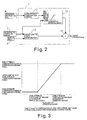
- FIG. 2 is a block diagram showing the vehicle driving force control apparatus in accordance with the first embodiment.
- the vehicle driving force control apparatus of the first embodiment basically comprises the target driving force computing component 1, the requested driving force detecting component 2, the vehicle speed detecting component 3, and the zone attribute detecting component 4.
- the target driving force computing component 1 further comprises a target driving force determination section 10, a zone attribute compensation control section 11, a compensation driving force upper limit value setting section 12, and an adder 13.
- the target driving force computing component 1 is configured and arranged to compute a target driving force that reflects a driver's request using information obtained from the requested driving force detecting component 2, the vehicle speed detecting component 3 and the zone attribute detecting component 4.
- the requested driving force detecting component 2 is configured and arranged to detect a requested driving force that corresponds to a driver's request.
- the requested driving force detecting component 2 is preferably an accelerator operation amount detecting component that is configured and arranged to detect an accelerator operation amount by which the driver operates the accelerator pedal P.
- the requested driving force detecting component 2 can be any device that detects the requested driving force measured from the accelerator operation of the driver, such as accelerator operation amount, throttle valve opening, engine intake volume, or the rate of change of any of these values.
- the vehicle speed detecting component 3 is configured and arranged to detect a vehicle speed.
- the vehicle speed detecting component 3 can be any component that has a function of detecting a vehicle speed, such as a transmission output shaft rotation sensor or a wheel speed sensor.
- the zone attribute detecting component 4 is configured and arranged to detect zone attribute information describing what type of road the vehicle is traveling on, e.g., highway, general road, narrow alley, congested road.
- a "road type” as used herein means a road that is characterized or classified based upon at least one of the following factors: speed limit, type of access, number of intersections, number of lanes, and the like.
- the zone attribute detecting component 4 is preferably an onboard navigation system that acquires road information, map data, and congestion information.
- the zone attribute detecting component 4 can also be any receiver or the like that receives road information from infrastructure installed along roads.
- the zone attribute detecting component 4 of the first embodiment preferably includes the onboard navigation system that calculates the current position periodically according to a fixed cycle using three types of signal that are indicative of: a traveling distance of the vehicle determined from a vehicle speed sensor, a turning angle of the vehicle determined from a gyro (angular velocity sensor), and a traveling direction of the vehicle determined from a GPS antenna (GPS information).
- the current position is identified by comparing or map matching the calculated current position to map data.
- the map data is read from a map CD-ROM stored in a CD-ROM drive and indicated on a display as a current position mark.
- a "zone attribute" is defined an external environmental factor that does not affect the vehicle physically but changes the vehicle behavior desired by the driver, e.g., highway, general road, narrow alley, or congested road.
- hills, snowy roads, wet roads, etc. are not the zone attributes because these external environmental factors change the traveling resistance of the vehicle and the gripping force of the tires with respect to the road surface and thus, affect the vehicle physically.
- roads are divided into four zone attributes, i.e., highway, general road, alley/narrow road, and congested road.
- zone attributes are also acceptable for other external environmental factors that do not affect the vehicle physically to be used as zone attributes.
- zone attributes it is also acceptable to divide the zone attributes into smaller categories by adding such factors as road width, road curvature, and degree of congestion to determine a zone attribute driving force, decrease/increase rates of a compensation value, based on these categories.
- the target driving force determination section 10 of the target driving force computing component 1 is configured to determine an initial target driving force (i.e., steady state target driving force) based on the vehicle speed detected by the vehicle speed detecting component 3 and an absolute value of the accelerator operation amount detected by the requested driving force detecting component 2. More specifically, the target driving force determination section 10 is configured to use an accelerator operation amount versus convergent vehicle speed characteristic determined based on the traveling resistance during steady state travel to determine the steady state target driving force, which is defined mainly in relation to the vehicle speed.
- an initial target driving force i.e., steady state target driving force
- the zone attribute compensation control section 11 of the target driving force computing component 1 is configured to calculate a compensation driving force that represents the amount by which the driver's desired acceleration distribution changes due to a difference zone attributes detected by the zone attribute detecting component 4.
- the compensation driving forces calculated by the zone attribute compensation control section 11 preferably include positive compensation driving forces that increase the target driving force and negative compensation driving forces that decrease the target driving force.
- the zone attribute compensation control section 11 is configured to calculate a large positive compensation driving force when the vehicle is on a highway.
- the zone attribute compensation control section 11 is configured to calculate a small compensation or zero compensation driving force when the vehicle is on a general road.
- the zone attribute compensation control section 11 is configured to calculate a negative compensation driving force when the vehicle is on an alley/narrow road. When any of these roads is congested, the calculated compensation driving force is decreased by a predetermined value that corresponds to a change in a desired driving force due to the congestion.
- the compensation driving force upper limit value setting section 12 of the target driving force computing component 1 is configured to set an upper limit value of the compensation driving force. More specifically, the compensation driving force upper limit value setting section 12 is configured to set the upper limit value of the compensation driving force in response to a value of the accelerator operation amount (the requested driving force) detected by the requested driving force detecting component 2, as shown in Figure 3.
- the compensation driving force upper limit value setting section 12 is configured to set the upper limit value to a zone attribute compensation minimum compensation driving force when the accelerator operation amount is less than or equal to a zone attribute compensation minimum accelerator operation amount (a first prescribed operation amount).
- the compensation driving force upper limit value setting section 12 is configured to set the upper limit value to a value that is proportional to the accelerator operation amount when the accelerator operation amount is between the zone attribute compensation minimum accelerator operation amount and a zone attribute compensation maximum accelerator operation amount (a second prescribed operation amount).
- the compensation driving force upper limit value setting section 12 is configured to set the upper limit value to a zone attribute compensation maximum compensation driving force when the accelerator operation amount is greater than or equal to the zone attribute compensation maximum accelerator operation amount.
- the zone attribute compensation minimum accelerator operation amount is preferably set to an accelerator operation amount at which the driver's intention to maintain the vehicle speed is clear.
- the zone attribute compensation minimum compensation driving force is preferably set to a compensation driving force value corresponding to steady state travel on a road type with a zone attribute that has a larger positive value of the compensation driving force.
- the zone attribute compensation maximum accelerator operation amount is preferably set to an accelerator operation amount at which the driver's intention to accelerate is clear.
- the zone attribute compensation upper limit compensation driving force is preferably set to a compensation driving force value corresponding to a prescribed upper limit of compensation value based on a road type with a zone attribute that has a larger positive value of the compensation driving force.
- the compensation driving force upper limit value setting section 12 is further configured not to limit the compensation driving force based on the accelerator operation amount when the target driving force is decreased by the compensation driving force calculated based on the zone attribute. If the upper limit value limitation based on the accelerator operation amount is executed when the zone attribute compensation value is a negative value, such as when the vehicle is on an alley/narrow road, then the increase and decrease of the accelerator operation amount and the target driving force will be reversed. Thus, this limitation should not be executed in such a case. Therefore, the zone attribute compensation minimum compensation driving force is preferably set to a value of zero or greater.
- the compensation driving force is a negative value that decreases the target driving force
- the limitation on the compensation driving force which is based on the accelerator operation amount by the driver, automatically ceases to be in effect.
- a feeling of abnormality during the accelerator operation can be eliminated when the target driving force is decreased by the zone attribute compensation driving force.
- the compensation driving force calculated by the zone attribute compensation control section 11 is limited by the upper limit value set by the compensation driving force upper limit value setting section 12. Then, the resulting value is outputted to the adder 13 as a final compensation driving force, which is used to adjust the target driving force that was determined by the target driving force determination section 10.
- the adder 13 is configured to add the initial target driving force (steady state target driving force) from the target driving force determination section 10 and the final compensation driving force from the compensation driving force upper limit setting section 12 together.
- the resulting sum value from the adder 13 is outputted as the final target driving force.
- the target driving force outputted by the adder 13 is received by a driving force control component of the vehicle.
- the driving force control component is preferably configured and arranged to control the actual driving force imparted to the drive wheels so as to match the target driving force.
- the driving force control component can be any device such as a drive output control component for an engine, motor, or other drive source, a gear ratio control means for a transmission provided so as to be connected to the drive source, or a system that combines a drive source output control means and a gear ratio control means.
- the distribution of driver's desired acceleration differs depending on the type of road on which the vehicle is traveling.
- the main types of accelerator operation are for maintaining constant speed travel in the vicinity of a designated speed limit and occasionally for accelerating for passing.
- the types of accelerator operations are limited to deceleration for the purpose of stopping and acceleration from a stopped condition toward the designated speed limit.
- the change in zone attribute is read from map data of a navigation system, and the target driving force is changed in response to the change in the driver's desired acceleration at that zone attribute.
- the driving force achieved in response to depressing the accelerator with a certain amount will be preferably larger than the driving force achieved on a general road in response to depressing the accelerator with the same amount.
- the driving force achieved in response to depressing the accelerator with a certain amount will be preferably smaller than the driving force achieved on a general road in response to depressing the accelerator with the same amount.
- a vehicle driving force characteristic that matches the current road environment or the zone attribute can be achieved.
- the target driving force is increased or decreased even when increasing or decreasing the target driving force is not desirable.
- Figure 4 is a diagram showing an accelerator operation amount characteristic and a target driving force characteristic for a case in which the target driving force is adjusted by a zone attribute compensation driving force without any consideration in an accelerator operation amount.
- a zone attribute that corresponds to the highway is detected based on map data from a navigation system, and thus, the target driving force is adjusted to a larger value.
- the target driving force will be adjusted even if the vehicle is traveling at a low speed for which increasing the driving force is undesirable.
- the driver will need to back off the accelerator to maintain the vehicle speed, as seen in Figure 4.
- the zone attribute compensation increases the driving force in the same manner as when the accelerator is depressed, the vehicle will accelerate if the driver does not back off the accelerator.
- the target driving force is adjusted by a compensation driving force that is limited by a value determined based on the accelerator operation amount. More specifically, the compensation driving force calculated by the zone attribute compensation control section 11 is limited by the compensation driving force upper limit value setting section 12. Therefore, the compensation driving force based on the zone attribute is significantly reduced in regions in which the accelerator operation amount is relatively small. Consequently, as shown in Figure 5, when the vehicle moves from a general road to a highway, most of the zone attribute compensation portion is reduced by the upper limit value limitation which is based on the accelerator operation amount. As a result, the amount by which the driver has to back off the accelerator to maintain the vehicle speed in the initial stage of transferring from the general road to the highway is reduced.
- the vehicle driving force control apparatus eliminates unnecessary accelerator operation.
- the compensation driving force based on the zone attribute is substantially reduced in these regions where the driver keeps the accelerator operation amount small.
- the compensation driving force based on the zone attribute will increase in response to the accelerator operation amount, as seen in Figure 5.
- the amount by which the target driving force is compensated based on the zone attribute is increased in regions where the driver depresses the accelerator greatly with the intention of accelerating.
- the target driving force is increased in a faster rate than on a general road. Accordingly, a good response characteristic to the driver's accelerator depression operation can be achieved.
- the vehicle driving force control apparatus of the second embodiment of the present invention differs from the first embodiment in that a target driving force computing component 101 is used instead of the target driving force computing component 1 of the first embodiment.
- the target driving force computing component 101 of the second embodiment includes a steady state target driving force determination section 110a (i.e., target driving force determination section), a transitional target driving force determination section 110b, a zone attribute compensation control section 111, a first adder 115 and a second adder 116.
- the transitional driving force determination section 110b is configured to compute a compensation amount or a transitional target driving force in response to a change in a steady state target driving force that is determined by the steady state target driving force determination section 110a.
- compensation based on zone attribute is only applied to the transitional target driving force.
- the steady state target driving force determination section 110a is configured to determine the steady state target driving force based on an accelerator operation amount detected by the requested driving force detecting component 2 and a vehicle speed detected by the vehicle speed detecting component 3.
- the zone attribute compensation control section 111 is configured to calculate a compensation driving force based on a zone attribute detected by the zone attribute detecting component 4.
- the first adder 115 is configured to add the steady state target driving force determined in the steady state target driving force determination section 110a and the compensation driving force calculated in the zone attribute compensation control section 111.
- the first adder 115 is further configured to output the resulting sum value to the transitional target driving force determination section 110b.
- the transitional target driving force determination section 110b is configured to determine the transitional target driving force using the sum of the steady state target driving force determined in the steady state target driving force determination section 110a and the compensation driving force calculated in the zone attribute compensation control section 111 that is inputted from the first adder 115.
- the target driving force is preferably compensated based on so called a transient response which is determined based on the change in the steady state target driving force (e.g., the vehicle speed for first order derivative, the acceleration for second order derivative, and higher number derivatives). Accordingly, the target driving force is compensated such that the change in the steady state target driving force is amplified.
- the transient response as used herein is a frequency characteristic such as "first order delay" used in control engineering.
- the transitional target driving force determination section 110b is preferably configured to determine the transitional target driving force based on such a first order delay frequency characteristic.
- it is also possible to determine the transitional target driving force by referring a prescribed data map for the rate of change in the target driving force and a corresponding compensation value.
- other various methods and/or calculations can be utilized to determine the transitional target driving force based on the steady state target driving force determined in the steady state target driving force determination section 110a and the compensation driving force calculated in the zone attribute compensation control section 111.
- the transitional target driving force determination section 110b is further configured to output the transitional target driving force to the second adder 116.
- the second adder 116 is configured to add the steady state target driving force determined by the steady state target driving force determination section 110a and the transitional target driving force determined by the transitional target driving force determination section 110b.
- the second adder 116 is configured to set the resulting sum value as a target driving force.
- the accelerator operation characteristic is as shown in Figure 7.
- Accelerator openings corresponding to low-speed travel will fluctuate only in a transitional manner, and thus, an additional accelerator operation is almost eliminated.
- a compensation portion due to a change in zone attributes is added in a transitional manner.
- the compensation portion due to a change in zone attributes does not become a problem because the original compensation gradient based on zone attributes would be expected to increase the target driving force at a rate of change that is barely detectable.
- the transitional target driving force is computed in accordance with the change in the steady state target driving force. Moreover, a compensation based on the zone attribute is executed only on the transitional target driving force. For example, when the vehicle is on a highway, and thus, the desired acceleration is larger than on a general road, the transitional target driving force will become larger due to the zone attribute compensation portion. Consequently, the change in the driver's desired acceleration caused by the change in zone attribute can be accommodated.
- the steady state driving force is compensated transitionally by the transitional target driving force determined based on the increase in accelerator depression amount in accordance with the accelerator operation as shown in Figure 8.
- the compensation based on zone attribute contributes such that the rise in target driving force with respect to the accelerator depression operation has a larger gain and the acceleration is higher than when there is no zone attribute compensation portion as previously described in Figure 8.
- a target driving force can be obtained which both eliminates unnecessary accelerator operation by the driver and responds to zone attribute changes in a highly suitable manner. More specifically, in this second embodiment, the target driving force is increased with a larger gain than in the first embodiment when the larger driving force is desired by the driver while the unnecessary increase of the driving force is eliminated when increasing the driving force is not desirable.
- the vehicle driving force control apparatus of the third embodiment of the present invention differs from the first embodiment in that a target driving force computing component 201 is used instead of the target driving force computing component 1 of the first embodiment.
- the target driving force computing component 201 of the third embodiment includes a steady state target driving force determination section 210a, a transitional target driving force determination section 210b, a zone attribute compensation control section 211, a compensation driving force upper limit value setting section 212, a first adder 215 and a second adder 216.
- the steady state target driving force determination section 210a is configured to determine a steady state target driving force of the target driving force based on an accelerator operation amount detected by the requested driving force detecting component 2 and a vehicle speed detected by the vehicle speed detecting component 3.
- the transitional target driving force determination section 210b is configured to determine a transitional target driving force based on a change in the steady state target driving force to compute the compensation amount.
- a compensation based on the zone attribute is applied only to the transitional target driving force.
- the compensation based on the zone attribute is limited with a value determined in the compensation driving force upper limit value setting section 212.
- the compensation driving force upper limit value setting section 212 is preferably configured to set the upper limit value of the compensation driving force in the same manner as the compensation driving force upper limit value setting section 12 of the first embodiment.
- the first adder 215 is configured to add the steady state target driving force determined by the steady state target driving force determination section 210a and the compensation driving force based on the zone attribute that is limited by a value determined in the compensation driving force upper limit value setting section 212.
- the first adder 215 is further configured to output the sum value to the transitional target driving force determination section 214.
- the transitional target driving force determination section 210b is configured to determine the transitional target driving force using the sum of the steady state target driving force determined in the steady state target driving force determination section 210a and the compensation driving force based on the zone attribute that is limited by a value determined in the compensation driving force upper limit value setting section 212 that is inputted from the first adder 215.
- the transitional target driving force determination section 210b is preferably configured to determine the transitional target driving force based on a first order delay frequency characteristic or a prescribed data map.
- the transitional target driving force determination section 210b is further configured to output the transitional target driving force to the second adder 216.
- the second adder 216 is configured to add the steady state target driving force determined by the steady state target driving force determination section 210a and the transitional target driving force determined by the transitional target driving force determination section 210b.
- the second adder 216 is configured to set the resulting sum value as a target driving force.
- the accelerator depression increase portion is compensated transitionally in accordance with the accelerator operation.
- the compensation driving force based on the zone attribute is increased as the accelerator depression amount increases according to a zone attribute compensation driving force upper limit value characteristic as previously described in Figure 3. Therefore, as shown in Figure 12, the increasing zone attribute compensation portion is added thereto and contributes to the rise in target driving force. As a result, the rise in target driving force with respect to the accelerator depression operation has a larger gain and the acceleration is higher.
- the compensation driving force calculated by the zone attribute compensation control section 211 is limited by the upper limit value determined in the compensation driving force upper limit value setting section 212, and the resulting value is used to determine the transitional target driving force, a target driving force can be obtained which both eliminates unnecessary accelerator operation by the driver in an effective manner and responds to zone attribute changes in a highly suitable manner.
- the zone attribute compensation control section 11 is configured to divide roads into a plurality of types, determine at least one attribute for each road type, and compute a compensation driving force in response to the change in desired driving force due to the attribute of the particular road type. As a result, the compensation driving force, which is responsive to the driver's desired driving force based on the attribute of the road, can be obtained.
- the zone attribute compensation control section 11 in accordance with the present invention is preferably configured and arranged so as to output one of the following as the zone attribute compensation driving force: a highway compensation driving force (positive value), an alley/narrow road compensation driving force (negative value), or a general road compensation driving force (zero).
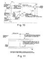
- FIG. 13 is a block diagram showing the zone attribute compensation control section 11 of the vehicle driving force control apparatus in accordance with the present invention.
- the zone attribute compensation control section 11 basically includes a map data determination portion 13a, a highway signal generating portion 13b, a highway compensation driving force setting portion 13c, an alley/narrow road signal generating portion 13d, an alley/narrow road compensation driving force setting portion 13e, a zero setting device 13f, a first comparator 13g, a second comparator 13h, a first switch device 13i, and a second switch device 13j.
- the map data determination portion 13a is configured to output signals that correspond to zone attributes of roads on which the vehicle travels when it determines the zone attributes based on vehicle position information and map data from the zone attribute detecting component 4. More specifically, the map data determination portion 13a is configured to output a highway signal when it determines that the vehicle is traveling (according to the map) on a highway or other similar road where the vehicle speed is high during steady state travel. Moreover, the map data determination portion 13a is configured to output an alley/narrow road signal when it determines that the vehicle is traveling (according to the map) on an alley, narrow road, or other similar road where the vehicle speed is low during steady state travel.
- the highway signal generation portion 13b is configured to produce a reference (highway) signal that is equivalent to a signal outputted from the map data determination section 13a, which indicates that the vehicle is traveling on a road with a zone attribute of a highway.
- the highway compensation driving force setting portion 13c is configured to set the highway compensation driving force such that the lower the vehicle speed is the larger the highway compensation driving force is, as shown in Figure 14.
- a characteristic can be created that allows high acceleration to be obtained readily when traveling on a low vehicle speed region of a highway and enables stable travel with the flow when traveling on a high vehicle speed region of the highway.
- the low vehicle speed region is generally a region from which high acceleration is executed in order to join the flow of traffic on the highway. After the vehicle has accelerated to the vicinity of the speed limit, high acceleration is no longer requested because the vehicle is required merely to maintain a state of traveling with the flow of the traffic.
- the highway compensation driving force setting portion 13c is configured to set the highway compensation driving force in response to the vehicle speed as shown in Figure 14.
- the alley/narrow road signal generating portion 13d is configured to produce a reference (alley/narrow road) signal that is equivalent to a signal outputted from the map data determination section 13a, which indicates that the vehicle is traveling on a road with a zone attribute of an alley/narrow road.
- the alley/narrow road compensation driving force setting portion 13e is configured to set a negative-valued alley/narrow road compensation driving force.
- the first comparator 13g is configured to output a command instructing the first switch device 13i to switch from the NO position to the YES position when highway signals that are equal are outputted from both the map data determination portion 13a and the highway signal generating portion 13b.
- the second comparator 13h is configured to output a command instructing the second switch device 13j to switch from the NO position to the YES position when alley/narrow road signals that are equal are outputted from both the map data determination portion 13a and the alley/narrow road signal generating portion 13d.
- the first comparator 13g is further configured to add a highway compensation driving force to the target driving force upon switching from zero compensation driving force to highway compensation driving force. Moreover, the first comparator 13g is configured to increase the compensation driving force at a prescribed rate of change until the highway compensation driving force is reached. As a result, the driving force can be increased smoothly while maintaining stable vehicle behavior.
- the second comparator 13h is further configured to subtract an alley/narrow road compensation driving force from the target driving force upon switching from zero driving force to alley/narrow road compensation driving force.
- the second comparator 13h is configured to decrease the compensation driving force at a prescribed rate of change until the alley/narrow road compensation driving force is reached. As a result, the driving force can be decreased smoothly while maintaining stable vehicle behavior.
- the first switch device 13i switches from the NO position to the YES position and the second switch device 13j remains in the NO position.
- the zone attribute compensation driving force changes from a zero driving force to a highway compensation driving force.
- the target driving force increases by an amount that increases gradually from zero to the highway compensation driving force. Accordingly, the target driving force is gradually adjusted to a value to which prescribed highway compensation driving force portion have been added.
- the driving force increases even if the accelerator operation amount remains the same.
- the vehicle accelerates smoothly in response to the change in the driver's desired acceleration distribution that changes as the zone attribute changes from general road to highway.
- the first switch device 13i remains in the NO position and the second switch device 13j switches from the NO position to the YES position.
- the zone attribute compensation driving force changes from zero driving force to alley/narrow road compensation driving force, which is set to a negative value.
- the target driving force decreases by an amount that decreases gradually from zero to the alley/narrow road compensation driving force. Accordingly, the target driving force is gradually adjusted to a value from which the set alley/narrow road compensation driving force portion has been subtracted.
- alternate zone attribute compensation control section 11a will be described in accordance with the present invention.
- the alternate zone attribute compensation control section 11a can be replaced with the zone attribute compensation control section 11 described above.
- the alternate zone attribute compensation control section 11a can be used in each of the above embodiments of the present invention.
- the parts of the alternate zone attribute compensation control section 11a that are identical to the parts of the zone attribute compensation control section 11 will be given the same reference numerals as the parts of the zone attribute compensation control section 11.
- the descriptions of the parts of the alternate zone attribute compensation control section 11a that are identical to the parts of the zone attribute compensation control section 11 may be omitted for the sake of brevity.
- the desired deceleration rate of the vehicle speed when the vehicle is entering a general road from a highway is different from the desired deceleration rate of the vehicle speed when the vehicle is entering to an alley from a highway.
- the compensation driving force should be set to decrease at a prescribed decrease rate depending upon which zones the vehicle is transferring to and from.
- the prescribed decrease rate of the compensation driving force for entering a general road from a highway should be different from the prescribed decrease rate of the compensation driving force for entering an alley from a general road. Therefore, it is desired to set a prescribed optimum rate of change with prescribed increase and decrease rates of the compensation driving force that corresponds to each situation and each zone attribute.
- the alternate zone attribute compensation control section 11a is further configured to set the prescribed increase and decrease rates of the compensation driving force based on the attribute of the road type when a zone attribute compensation driving force is outputted.
- the compensation driving force based on the zone attribute is decreased according to a prescribed optimum decrease rate.
- the compensation driving force based on the zone attribute is decreased according to a different prescribed optimum decrease rate.
- the alternate zone attribute compensation control section 11a includes a map data determination portion 13a, a highway signal generating portion 13b, a highway compensation driving force setting portion 13c, an alley/narrow road signal generating portion 13d, an alley/narrow road compensation driving force setting portion 13e, a zero setting device 13f, a first comparator 13g, a second comparator 13h, a first switch device 13i, and a second switch device 13j.
- These portions and devices basically function as the same portions and devices of the zone attribute compensation control section 11 that are given the same reference numerals.
- the alternate zone attribute compensation control section 11a further includes a highway compensation driving force increase rate setting portion 16a, a highway compensation driving force decrease rate setting portion 16b, an alley/narrow road compensation force increase rate setting portion 16c, an alley/narrow road compensation force decrease rate setting portion 16d, a first adder 16e, a second adder 16f, a minimum value selector 16g, a maximum value selector 16h, a third comparator 16i, a third switching device 16j, an delaying device 16k, zero setting devices 13f' and 13f", first switch devices 13i' and 13i", and second switch devices 13j' and 13j".
- the highway compensation driving force increase rate setting portion 16a is configured to set the prescribed optimum rate of change of the compensation driving force to increase at the prescribed optimum increase rate (i.e., amount of compensation driving force increase per processing cycle) when the vehicle enters a highway from a general road.
- the highway compensation driving force decrease rate setting portion 16b is configured to set the prescribed optimum rate of change of the compensation driving force to decrease at the prescribed optimum decrease rate (i.e., amount of compensation driving force decrease per processing cycle) when the vehicle enters a general road from a highway.
- the alley/narrow road compensation driving force increase rate setting portion 16c is configured to set the prescribed optimum rate of change of the compensation driving force to increase at the prescribed optimum increase rate (i.e., amount of compensation driving force increase per processing cycle) when the vehicle enters a general road from an alley.
- the alley/narrow road compensation driving force decrease rate setting portion 16d is configured to set the prescribed optimum rate of change of compensation driving force to decrease prescribed optimum decrease rate (i.e., amount of compensation driving force decrease per processing cycle) when the vehicle enters an alley from a general road.
- prescribed optimum decrease rate i.e., amount of compensation driving force decrease per processing cycle
- the zone attribute compensation driving force can always be increased or decreased at the optimum increase rate or decrease rate that correspond to each zone attribute.
- the first adder 16e is configured to add the prescribed increase rate that is determined by either the highway compensation driving force increase rate setting portion 16a or the alley/narrow road compensation driving force increase rate setting portion 16c to the zone attribute compensation driving force of the previous cycle to obtain the zone attribute compensation driving force for the current cycle.
- the first adder 16e is further configured to output the result to the minimum value selector 16g.
- the second adder 16f is configured to add the prescribed decrease rate that is determined by either the highway compensation driving force decrease rate setting portion 16b or the alley/narrow road compensation driving force decrease rate setting portion 16d to the zone attribute compensation driving force of the previous cycle to obtain the zone attribute compensation driving force for the current cycle.
- the second adder 16f is further configured to output the result to maximum value selector 16h.
- the minimum value selector 16g is configured to select the minimum value between the compensation driving force (target value) selected at that time and the zone attribute compensation driving force of the current cycle that is inputted by the first adder 16e when the driving force is being adjusted to a larger value.
- the maximum value selector 16h is configured to select the maximum [minimum] value between the compensation driving force (target value) selected at that time and the zone attribute compensation driving force of the current cycle that is inputted by the second adder 16f when the driving force is being adjusted to a smaller value.
- the third comparator 16i is configured to compare the zone attribute compensation driving force of the previous cycle to the compensation driving force (target driving force) selected.
- the third comparator 16i is further configured to set the third switch device 16j to the YES position when the driving force is being adjusted to a larger value and to the NO position when the driving force is being adjusted to a smaller value.
- the delaying device 16k is configured to output the zone attribute compensation driving force of the previous cycle, which is delayed with respect to the currently outputted zone attribute compensation driving force, to the first adder 16e, second adder 16f, and third switch device 16j.
Landscapes
- Engineering & Computer Science (AREA)
- Chemical & Material Sciences (AREA)
- Combustion & Propulsion (AREA)
- Transportation (AREA)
- Mechanical Engineering (AREA)
- Control Of Driving Devices And Active Controlling Of Vehicle (AREA)
- Control Of Vehicle Engines Or Engines For Specific Uses (AREA)
- Controls For Constant Speed Travelling (AREA)
- Control Of Transmission Device (AREA)
Applications Claiming Priority (2)
| Application Number | Priority Date | Filing Date | Title |
|---|---|---|---|
| JP2002141528 | 2002-05-16 | ||
| JP2002141528A JP2003327013A (ja) | 2002-05-16 | 2002-05-16 | 車両の駆動力制御装置 |
Publications (1)
| Publication Number | Publication Date |
|---|---|
| EP1362735A2 true EP1362735A2 (de) | 2003-11-19 |
Family
ID=29267813
Family Applications (1)
| Application Number | Title | Priority Date | Filing Date |
|---|---|---|---|
| EP03010826A Withdrawn EP1362735A2 (de) | 2002-05-16 | 2003-05-14 | Steuerung der Antriebskraft eines Fahrzeugs |
Country Status (3)
| Country | Link |
|---|---|
| US (1) | US6741923B2 (de) |
| EP (1) | EP1362735A2 (de) |
| JP (1) | JP2003327013A (de) |
Cited By (1)
| Publication number | Priority date | Publication date | Assignee | Title |
|---|---|---|---|---|
| WO2006042630A1 (de) * | 2004-10-20 | 2006-04-27 | Bayerische Motoren Werke Aktiengesellschaft | Längsdynamiksteuersystem in kraftfahrzeugen |
Families Citing this family (23)
| Publication number | Priority date | Publication date | Assignee | Title |
|---|---|---|---|---|
| JP4300728B2 (ja) * | 2001-10-17 | 2009-07-22 | マツダ株式会社 | 車両の変速操作装置 |
| DE10235363A1 (de) * | 2002-08-02 | 2004-02-19 | Robert Bosch Gmbh | Verfahren zur Regelung der Geschwindigkeit eines Fahrzeugs |
| JP4788464B2 (ja) * | 2006-04-28 | 2011-10-05 | 日産自動車株式会社 | 車間維持支援装置および車間維持支援方法 |
| US7728448B2 (en) * | 2006-05-09 | 2010-06-01 | Azure Dynamics, Inc. | Process and apparatus for reducing nitrogen oxide emissions in genset systems |
| WO2008000071A1 (en) | 2006-06-26 | 2008-01-03 | Azur Dynamics Inc. | Method, apparatus , signals , and media, for selecting operating conditions of a genset |
| US7826939B2 (en) * | 2006-09-01 | 2010-11-02 | Azure Dynamics, Inc. | Method, apparatus, signals, and medium for managing power in a hybrid vehicle |
| US9645968B2 (en) | 2006-09-14 | 2017-05-09 | Crown Equipment Corporation | Multiple zone sensing for materials handling vehicles |
| US8970363B2 (en) | 2006-09-14 | 2015-03-03 | Crown Equipment Corporation | Wrist/arm/hand mounted device for remotely controlling a materials handling vehicle |
| US9207673B2 (en) * | 2008-12-04 | 2015-12-08 | Crown Equipment Corporation | Finger-mounted apparatus for remotely controlling a materials handling vehicle |
| US9122276B2 (en) | 2006-09-14 | 2015-09-01 | Crown Equipment Corporation | Wearable wireless remote control device for use with a materials handling vehicle |
| JP5098736B2 (ja) * | 2008-03-25 | 2012-12-12 | 株式会社明電舎 | 車両速度制御装置 |
| US9522817B2 (en) | 2008-12-04 | 2016-12-20 | Crown Equipment Corporation | Sensor configuration for a materials handling vehicle |
| JP5552455B2 (ja) * | 2011-03-16 | 2014-07-16 | 富士重工業株式会社 | 車両用運転支援装置 |
| US9085237B2 (en) * | 2011-10-03 | 2015-07-21 | Fuji Jukogyo Kabushiki Kaisha | Speed limiter |
| JP5857947B2 (ja) * | 2012-12-11 | 2016-02-10 | トヨタ自動車株式会社 | 駆動力制御装置 |
| JP2014148200A (ja) * | 2013-01-31 | 2014-08-21 | Denso Corp | 車両制御装置 |
| KR101964026B1 (ko) * | 2015-11-09 | 2019-03-29 | 닛산 지도우샤 가부시키가이샤 | 제구동력 제어 방법 및 제구동력 제어 장치 |
| EP4269157A3 (de) | 2019-02-01 | 2023-12-20 | Crown Equipment Corporation | Bordladestation für eine fernsteuerungsvorrichtung |
| US11641121B2 (en) | 2019-02-01 | 2023-05-02 | Crown Equipment Corporation | On-board charging station for a remote control device |
| JP7360290B2 (ja) * | 2019-09-26 | 2023-10-12 | 株式会社Subaru | 車両の走行制御装置 |
| KR102844524B1 (ko) | 2020-08-11 | 2025-08-12 | 크라운 이큅먼트 코포레이션 | 원격 제어 장치 |
| JP7786055B2 (ja) * | 2021-07-02 | 2025-12-16 | 日産自動車株式会社 | 駆動力制御方法及び駆動力制御装置 |
| WO2024161542A1 (ja) * | 2023-02-01 | 2024-08-08 | 日産自動車株式会社 | 駆動力制御方法及び駆動力制御装置 |
Family Cites Families (9)
| Publication number | Priority date | Publication date | Assignee | Title |
|---|---|---|---|---|
| JPH08282519A (ja) * | 1995-04-10 | 1996-10-29 | Mitsubishi Electric Corp | 電動パワーステアリング装置の制御装置 |
| DE19736406B4 (de) * | 1997-08-21 | 2007-05-16 | Siemens Ag | Einrichtung zum Steuern eines automatischen Getriebes für ein Kraftfahrzeug |
| US6188950B1 (en) * | 1997-10-27 | 2001-02-13 | Nissan Motor Co., Ltd. | System and method for controlling inter-vehicle distance to preceding vehicle for automotive vehicle equipped with the system and method |
| JP3704934B2 (ja) * | 1997-12-19 | 2005-10-12 | マツダ株式会社 | 流体継ぎ手の締結力制御装置 |
| US6371885B1 (en) * | 1999-04-01 | 2002-04-16 | Komatsu Ltd. | Working vehicle and vehicle speed control method thereof, variable power engine and power setting method thereof, and vehicle with variable power engine and power control method thereof |
| JP2001058564A (ja) * | 1999-08-24 | 2001-03-06 | Mazda Motor Corp | 自動車の旋回姿勢制御装置 |
| JP3622591B2 (ja) | 1999-10-08 | 2005-02-23 | 日産自動車株式会社 | 車両の駆動力制御装置 |
| JP2001171504A (ja) * | 1999-12-16 | 2001-06-26 | Nissan Motor Co Ltd | 路面摩擦係数推定装置 |
| US6574535B1 (en) * | 2000-05-31 | 2003-06-03 | General Motors Corporation | Apparatus and method for active driveline damping with clunk control |
-
2002
- 2002-05-16 JP JP2002141528A patent/JP2003327013A/ja active Pending
-
2003
- 2003-04-28 US US10/423,917 patent/US6741923B2/en not_active Expired - Fee Related
- 2003-05-14 EP EP03010826A patent/EP1362735A2/de not_active Withdrawn
Cited By (1)
| Publication number | Priority date | Publication date | Assignee | Title |
|---|---|---|---|---|
| WO2006042630A1 (de) * | 2004-10-20 | 2006-04-27 | Bayerische Motoren Werke Aktiengesellschaft | Längsdynamiksteuersystem in kraftfahrzeugen |
Also Published As
| Publication number | Publication date |
|---|---|
| JP2003327013A (ja) | 2003-11-19 |
| US20030216854A1 (en) | 2003-11-20 |
| US6741923B2 (en) | 2004-05-25 |
Similar Documents
| Publication | Publication Date | Title |
|---|---|---|
| US6741923B2 (en) | Vehicle driving force control apparatus | |
| JP5139939B2 (ja) | 車両の減速支援装置 | |
| JP4571757B2 (ja) | 車両の走行速度を制御するための方法及び装置 | |
| JP3620359B2 (ja) | 車両用走行制御装置 | |
| CN101152842B (zh) | 行驶控制装置 | |
| US7433772B2 (en) | Target speed control system for a vehicle | |
| US7155341B2 (en) | System and method for informing vehicle environment | |
| US8712664B2 (en) | Vehicle control apparatus | |
| US6554090B1 (en) | Automobile running control system | |
| EP1281561A2 (de) | Abstandsbezogenes Fahrgeschwindigkeitsregelsystem | |
| US10974723B2 (en) | Drive force control system for vehicle | |
| US6294986B1 (en) | Method and system for determining a regulator object | |
| JP2020001551A (ja) | 車両制御装置 | |
| US20020095254A1 (en) | Vehicular adaptive cruise control apparatus and method with preceding vehicle following control function | |
| KR20200116412A (ko) | 차량의 구동력 제어 장치 | |
| JP3793431B2 (ja) | オートクルーズ制御装置 | |
| JP4874725B2 (ja) | 車両用減速意志判定装置および走行制御装置 | |
| JP3365064B2 (ja) | 車両用走行制御装置 | |
| JPH0717298A (ja) | 自動車の走行制御装置 | |
| JPH10338056A (ja) | 車両用追従走行制御装置 | |
| JP2004086714A (ja) | 車両用減速制御装置 | |
| JPH11348599A (ja) | 車両の走行制御装置 | |
| JP4206762B2 (ja) | 自動変速機の制御装置 | |
| KR102583173B1 (ko) | 차량의 주행 제어 장치 및 방법 | |
| WO2024161542A1 (ja) | 駆動力制御方法及び駆動力制御装置 |
Legal Events
| Date | Code | Title | Description |
|---|---|---|---|
| PUAI | Public reference made under article 153(3) epc to a published international application that has entered the european phase |
Free format text: ORIGINAL CODE: 0009012 |
|
| 17P | Request for examination filed |
Effective date: 20030514 |
|
| AK | Designated contracting states |
Kind code of ref document: A2 Designated state(s): AT BE BG CH CY CZ DE DK EE ES FI FR GB GR HU IE IT LI LU MC NL PT RO SE SI SK TR |
|
| AX | Request for extension of the european patent |
Extension state: AL LT LV MK |
|
| STAA | Information on the status of an ep patent application or granted ep patent |
Free format text: STATUS: THE APPLICATION HAS BEEN WITHDRAWN |
|
| 18W | Application withdrawn |
Effective date: 20041201 |