EP1361455A2 - Gerät für die bildgebende magnetische Resonanz mit besonders hoher Empfindlichkeit - Google Patents
Gerät für die bildgebende magnetische Resonanz mit besonders hoher Empfindlichkeit Download PDFInfo
- Publication number
- EP1361455A2 EP1361455A2 EP02028840A EP02028840A EP1361455A2 EP 1361455 A2 EP1361455 A2 EP 1361455A2 EP 02028840 A EP02028840 A EP 02028840A EP 02028840 A EP02028840 A EP 02028840A EP 1361455 A2 EP1361455 A2 EP 1361455A2
- Authority
- EP
- European Patent Office
- Prior art keywords
- magnetic field
- coil
- protein
- magnetic resonance
- nuclear magnetic
- Prior art date
- Legal status (The legal status is an assumption and is not a legal conclusion. Google has not performed a legal analysis and makes no representation as to the accuracy of the status listed.)
- Withdrawn
Links
- 238000013421 nuclear magnetic resonance imaging Methods 0.000 title claims abstract description 26
- 238000005481 NMR spectroscopy Methods 0.000 claims abstract description 85
- 102000004169 proteins and genes Human genes 0.000 claims abstract description 59
- 108090000623 proteins and genes Proteins 0.000 claims abstract description 59
- 238000003384 imaging method Methods 0.000 claims abstract description 48
- 239000013078 crystal Substances 0.000 claims description 21
- 241001465754 Metazoa Species 0.000 claims description 13
- 239000000463 material Substances 0.000 claims description 9
- 239000007788 liquid Substances 0.000 claims description 8
- XLYOFNOQVPJJNP-UHFFFAOYSA-N water Substances O XLYOFNOQVPJJNP-UHFFFAOYSA-N 0.000 claims description 5
- PZKRHHZKOQZHIO-UHFFFAOYSA-N [B].[B].[Mg] Chemical compound [B].[B].[Mg] PZKRHHZKOQZHIO-UHFFFAOYSA-N 0.000 claims description 2
- 238000010171 animal model Methods 0.000 claims 1
- 238000000034 method Methods 0.000 abstract description 33
- 238000005516 engineering process Methods 0.000 abstract description 20
- 238000005259 measurement Methods 0.000 abstract description 20
- 239000000126 substance Substances 0.000 abstract description 6
- 230000004060 metabolic process Effects 0.000 abstract description 5
- 230000008569 process Effects 0.000 abstract description 5
- 239000000523 sample Substances 0.000 description 56
- 230000035945 sensitivity Effects 0.000 description 39
- 210000004027 cell Anatomy 0.000 description 28
- 238000010276 construction Methods 0.000 description 23
- 230000000052 comparative effect Effects 0.000 description 21
- 238000004458 analytical method Methods 0.000 description 16
- 238000001514 detection method Methods 0.000 description 16
- 230000006872 improvement Effects 0.000 description 13
- 238000011161 development Methods 0.000 description 11
- 238000001228 spectrum Methods 0.000 description 9
- 230000000694 effects Effects 0.000 description 7
- 230000007246 mechanism Effects 0.000 description 7
- 238000009825 accumulation Methods 0.000 description 6
- 230000006870 function Effects 0.000 description 6
- 239000001307 helium Substances 0.000 description 6
- 229910052734 helium Inorganic materials 0.000 description 6
- SWQJXJOGLNCZEY-UHFFFAOYSA-N helium atom Chemical compound [He] SWQJXJOGLNCZEY-UHFFFAOYSA-N 0.000 description 6
- 239000000243 solution Substances 0.000 description 6
- 238000013461 design Methods 0.000 description 5
- 238000000425 proton nuclear magnetic resonance spectrum Methods 0.000 description 5
- IJGRMHOSHXDMSA-UHFFFAOYSA-N Atomic nitrogen Chemical compound N#N IJGRMHOSHXDMSA-UHFFFAOYSA-N 0.000 description 4
- 238000004891 communication Methods 0.000 description 4
- 238000012360 testing method Methods 0.000 description 4
- RYGMFSIKBFXOCR-UHFFFAOYSA-N Copper Chemical compound [Cu] RYGMFSIKBFXOCR-UHFFFAOYSA-N 0.000 description 3
- 230000008901 benefit Effects 0.000 description 3
- 230000019522 cellular metabolic process Effects 0.000 description 3
- 238000005352 clarification Methods 0.000 description 3
- 239000010949 copper Substances 0.000 description 3
- 208000037265 diseases, disorders, signs and symptoms Diseases 0.000 description 3
- 230000004907 flux Effects 0.000 description 3
- 239000011521 glass Substances 0.000 description 3
- 238000004519 manufacturing process Methods 0.000 description 3
- 238000001208 nuclear magnetic resonance pulse sequence Methods 0.000 description 3
- 229910020073 MgB2 Inorganic materials 0.000 description 2
- QVGXLLKOCUKJST-UHFFFAOYSA-N atomic oxygen Chemical compound [O] QVGXLLKOCUKJST-UHFFFAOYSA-N 0.000 description 2
- 210000003850 cellular structure Anatomy 0.000 description 2
- 238000001816 cooling Methods 0.000 description 2
- 229910052802 copper Inorganic materials 0.000 description 2
- 238000002425 crystallisation Methods 0.000 description 2
- 230000008025 crystallization Effects 0.000 description 2
- 201000010099 disease Diseases 0.000 description 2
- 238000009826 distribution Methods 0.000 description 2
- 238000002474 experimental method Methods 0.000 description 2
- 238000009434 installation Methods 0.000 description 2
- 238000006241 metabolic reaction Methods 0.000 description 2
- 239000011785 micronutrient Substances 0.000 description 2
- 235000013369 micronutrients Nutrition 0.000 description 2
- 230000004048 modification Effects 0.000 description 2
- 238000012986 modification Methods 0.000 description 2
- 239000002547 new drug Substances 0.000 description 2
- 229910000657 niobium-tin Inorganic materials 0.000 description 2
- 229910052757 nitrogen Inorganic materials 0.000 description 2
- 238000005457 optimization Methods 0.000 description 2
- 239000001301 oxygen Substances 0.000 description 2
- 229910052760 oxygen Inorganic materials 0.000 description 2
- 230000029553 photosynthesis Effects 0.000 description 2
- 238000010672 photosynthesis Methods 0.000 description 2
- 230000000644 propagated effect Effects 0.000 description 2
- 239000012460 protein solution Substances 0.000 description 2
- 239000007787 solid Substances 0.000 description 2
- 239000000758 substrate Substances 0.000 description 2
- 208000020406 Creutzfeldt Jacob disease Diseases 0.000 description 1
- 208000003407 Creutzfeldt-Jakob Syndrome Diseases 0.000 description 1
- 208000010859 Creutzfeldt-Jakob disease Diseases 0.000 description 1
- 230000003466 anti-cipated effect Effects 0.000 description 1
- 239000007864 aqueous solution Substances 0.000 description 1
- 230000005540 biological transmission Effects 0.000 description 1
- 230000008859 change Effects 0.000 description 1
- 238000006243 chemical reaction Methods 0.000 description 1
- 230000001684 chronic effect Effects 0.000 description 1
- 206010012601 diabetes mellitus Diseases 0.000 description 1
- 230000006806 disease prevention Effects 0.000 description 1
- 238000004535 dynamic nuclear magnetic resonance Methods 0.000 description 1
- 238000013399 early diagnosis Methods 0.000 description 1
- 235000013305 food Nutrition 0.000 description 1
- 239000007789 gas Substances 0.000 description 1
- 238000010191 image analysis Methods 0.000 description 1
- 230000003993 interaction Effects 0.000 description 1
- 230000001678 irradiating effect Effects 0.000 description 1
- 238000002595 magnetic resonance imaging Methods 0.000 description 1
- 229910052751 metal Inorganic materials 0.000 description 1
- 239000002184 metal Substances 0.000 description 1
- 150000002894 organic compounds Chemical class 0.000 description 1
- -1 protein Chemical class 0.000 description 1
- 230000006916 protein interaction Effects 0.000 description 1
- 238000005086 pumping Methods 0.000 description 1
- 230000009467 reduction Effects 0.000 description 1
- 239000012488 sample solution Substances 0.000 description 1
- 238000005070 sampling Methods 0.000 description 1
- 238000012216 screening Methods 0.000 description 1
- 239000004065 semiconductor Substances 0.000 description 1
- 238000000926 separation method Methods 0.000 description 1
- 230000008054 signal transmission Effects 0.000 description 1
- 238000004088 simulation Methods 0.000 description 1
- 208000024891 symptom Diseases 0.000 description 1
Images





Classifications
-
- G—PHYSICS
- G01—MEASURING; TESTING
- G01R—MEASURING ELECTRIC VARIABLES; MEASURING MAGNETIC VARIABLES
- G01R33/00—Arrangements or instruments for measuring magnetic variables
- G01R33/20—Arrangements or instruments for measuring magnetic variables involving magnetic resonance
- G01R33/28—Details of apparatus provided for in groups G01R33/44 - G01R33/64
- G01R33/38—Systems for generation, homogenisation or stabilisation of the main or gradient magnetic field
- G01R33/381—Systems for generation, homogenisation or stabilisation of the main or gradient magnetic field using electromagnets
- G01R33/3815—Systems for generation, homogenisation or stabilisation of the main or gradient magnetic field using electromagnets with superconducting coils, e.g. power supply therefor
-
- G—PHYSICS
- G01—MEASURING; TESTING
- G01R—MEASURING ELECTRIC VARIABLES; MEASURING MAGNETIC VARIABLES
- G01R33/00—Arrangements or instruments for measuring magnetic variables
- G01R33/20—Arrangements or instruments for measuring magnetic variables involving magnetic resonance
- G01R33/44—Arrangements or instruments for measuring magnetic variables involving magnetic resonance using nuclear magnetic resonance [NMR]
- G01R33/48—NMR imaging systems
- G01R33/54—Signal processing systems, e.g. using pulse sequences ; Generation or control of pulse sequences; Operator console
- G01R33/56—Image enhancement or correction, e.g. subtraction or averaging techniques, e.g. improvement of signal-to-noise ratio and resolution
- G01R33/5604—Microscopy; Zooming
-
- G—PHYSICS
- G01—MEASURING; TESTING
- G01R—MEASURING ELECTRIC VARIABLES; MEASURING MAGNETIC VARIABLES
- G01R33/00—Arrangements or instruments for measuring magnetic variables
- G01R33/20—Arrangements or instruments for measuring magnetic variables involving magnetic resonance
- G01R33/44—Arrangements or instruments for measuring magnetic variables involving magnetic resonance using nuclear magnetic resonance [NMR]
- G01R33/46—NMR spectroscopy
- G01R33/465—NMR spectroscopy applied to biological material, e.g. in vitro testing
Definitions
- the present invention relates to a supersensitive nuclear magnetic resonance imaging apparatus, and mainly to a high resolution imaging of biosamples such as cells, organic tissues, laboratory small animals, or the like, or to growth of high-grade protein crystal using high resolution imaging, on-site observation of the process of growth, and a method of growth.
- NMR nuclear magnetic resonance
- the object of the present invention is a supersensitive nuclear magnetic resonance imaging apparatus having spatial resolutions not more than 1 micron, and more preferably, in the order of 0.1 micron, which is required for enabling the analysis of metabolism of cells or protein information network in cells in the living organisms such as small animals or cellular structures, that corresponds to a special imaging apparatus requiring high performance three digits higher in spatial resolution, at least one digit higher in field strength of a superconducting magnet, four digits higher in uniformity of magnetic fields, three digits higher in stability in comparison with a medical MRI image diagnostic apparatus used for laminagraphy of human bodies, which requires image resolution of so called millimeter category, and thus requiring completely different designing technology and apparatus manufacturing technology.
- the nuclear magnetic resonance imaging apparatus is known as a medical image diagnostic apparatus using a field strength in the range of 0.2 to 8 T for a partial or entire human body, and generally, magnetic fields in the order of 0.3 to 1.5 Tesla is used in many cases.
- MR imaging technology Japanese Society of Radiological Technology, published by Ohmsha, 2001.
- magnetic fields of not less than 0.5 Tesla are utilized, and spatial resolution of images in the medical nuclear magnetic resonance image diagnostic apparatus is generally 0.2 mm.
- a spectroscopic apparatus using high magnetic fields in the order of 14 to 21 T for the purpose of utilizing a nuclear magnetic resonance analyzing method for analyzing the structure of organic matters or protein is also developed.
- the latest invention relating to a typical apparatus structure to be used in the case of employing such high-magnetic-field NMR in nuclear magnetic resonance includes the invention relating to a superconducting magnet in JP-A-2000-147082 disclosing a typical structure of a multi-layer hollow solenoid coil, the invention relating to a signal detection technology in USP No.6121776 disclosing a birdcage superconducting detector coil, and the invention in JP-A-2000-266830 and in JP-A-6-237912 disclosing a signal detecting technologies using saddle type coils or birdcage coils in the related art.
- a high resolution nuclear magnetic resonance analyzing apparatus in the related art employs a superconducting magnetic apparatus constructed of the combination of solenoid coils that generate magnetic fields in the vertical direction for irradiating electromagnetic wave of 400 to 900 MHz to a sample and detecting resonant wave generated by the sample by the use of a saddle type or a birdcage detector coils.
- a detector that is cooled to low temperatures for reducing heat noise generated when receiving is used for improving S/N sensitivity ratio.
- the nuclear magnetic resonance spectroscopic apparatus has been improved in its sensitivity basically by maintaining the same basic structure of the system such as an antenna, magnet, and the like, and increasing the central magnetic field strength of the superconducting magnet. Therefore, though the highest NMR measurement sensitivity reported thus far is obtained by the NMR apparatus of 900 MHz using a large superconducting magnet having a central magnetic field of 21.1 Tesla, the basic structure of the apparatus is no different from the related art as in JP-A-2000-147082. Protein using a solution is generally used as a sample, improvement of the central magnetic field has effects on improvement of sensitivity in NMR spectroscopy and on identification of separation of chemical shift.
- JP-A-11-248810 a method of magnetizing a high temperature superconducting bulk magnet in the horizontal direction, and detecting the NMR signal by a solenoid coil is lately devised.
- JP-A-7-240310 a method of constructing a superconducting magnet and a cooling container suitable to be used in the general NMR for eliminating limitation of the height of the apparatus due to the height of the ceiling is disclosed.
- a method of improving the detection sensitivity required for a high resolution imaging and a technical application for uniformity of magnetic fields or time-based stability of the magnetic field are not shown.
- the present invention provides a method for enabling imaging of images on a scale one digit smaller than the cell size.
- the specification of uniformity of magnetic fields in the general NMR apparatus is 0.01 ppm in a sample space and 0.01 ppm/h in the time-based stability.
- the allowable error is 6Hz.
- the aforementioned nuclear magnetic resonance imaging requires a space and time-based resolution of at least 1.0 Hz or less, and preferably, of 0.5 Hz or less.
- the superconducting magnet or the detector coil must be optimally constructed in such a manner that such uniformity of magnetic field and the time-based stability can be realized. Therefore, performance of the NMR apparatus that has been generally used in the related art is not sufficient, and thus the stability and uniformity of magnetic field one digit higher than the related art are required.
- a method of supersensitive measurement using a solenoid coil can be performed only with a minute quantity of specific sample tube and a specific detector probe, but it cannot be applied to cell imaging due to the issue of resolution.
- a magnetic field was generated in the horizontal direction with a strong magnet and a NMR signal was detected with a solenoid coil
- only a magnetic field less than 10T could be generated on the surface of a high temperature superconducting body, and the magnetic field in the portion of the sample was several Tesla at the highest.
- this method it was impossible to generate a magnetic field not less than 11 Tesla that was required for imaging of cells, or preferably, not less than 14.1 Tesla, in the desired sample space. Further, in this method, it was substantially difficult to achieve a time-based stability of 1.0Hz/h or less required for imaging of cells due to the effect of a magnetic flux creeping phenomenon of the high temperature superconducting body. As regards the uniformity of magnetic field required for analysis of protein, it was also difficult to achieve the uniformity of magnetic field in the level less than 1.0 Hz in Proton nuclear magnetic resonance frequencies in a space of 10 mm (diameter) x 10 mm (length), because of non-uniformity caused by the manufacturing process of the high temperature superconducting bulk body material.
- the object of the present invention is to provide a novel nuclear magnetic resonance analyzing apparatus in which a sampling chamber of 1 to 30 mm in diameter that can accommodate the needs of biological study is used, sensitivity for measuring the NMR signal is increased to the value in the order of at least three times conventional value at least at 600 MHz (14.1T), and the time-based stability and the spatial uniformity of the superconducting magnet required for imaging analysis in the cell can be provided.
- the operating temperature of the system is not limited to 4.2 K. It is also possible to aim the extreme performance by the application of the present invention, and depending on the applications, operation at 1.8K at 21.1T or 900 MHz, which used to be the limit of the magnetic field in the related art, is also possible. In such a case, improvement of sensitivity to the value three times that in the related art is possible, and thus breakthrough of the limit of detection sensitivity by the magnetic field strength, which used to be impossible in the related art, could be achieved for the first time.
- the present nuclear magnetic resonance apparatus has been developed as a method in which solution sample is placed at the center of the multi-layer hollow solenoid coil having superior uniformity in magnetic fields and detected by a saddle-type or a birdcage antenna, in order to successfully combine the cost and installability.
- measurement sensitivity has been improved by intensifying the central magnetic field while maintaining this basic system of the NMR.
- an example of using a superconducting birdcage antenna to reduce heat noise is also reported.
- the point is to increase sensitivity by applying a detector coil of solenoid system as a sample space of 1 to 30 mm in diameter and 20 to 60 mm in height with at least 400 MHz, and preferably, in the order of 600 MHz to 900 MHz in Proton nuclear magnetic resonance frequencies.
- improvement of sensitivity of at least about 2.5 to 2.8 times must be expected by the difference among the form factors of the detector coil, and further improvement is expected by other factors, whereby the data accumulation time required for imaging may be reduced to one-tenth or less.
- the sample is inserted from the top of the apparatus in the vertical direction.
- the construction of the superconducting magnet differs from that of a simple solenoid magnet of the related art, and is required to be constructed of a laterally divided pair of split magnets.
- a superconducting magnet In order to be applied to a special analysis, such as imaging of metabolism or analysis of protein information network in a cell or between cells, as described above, it is necessary to optimally design and manufacture a superconducting magnet to have 1.0 Hz/h in Proton nuclear magnetic resonance frequencies in terms of time-based stability, and 1.0 Hz or less in terms of spatial uniformity in the sample space. It is a design being at least one digit stricter than that in the related art, and is not in the range that can be realized by simply combining the known arts.
- each split magnet is subjected to a sufficient design examination to achieve generation of magnetic field with high level of accuracy of 0.000 ppm, which is the limit of effective number of digits on the computer, and then constructed by optimally arranging and combining a coil formed of high magnetic field superconducting wire such as Nb 3 Sn and a low magnetic field superconducting coil formed of NbTi superconducting wire.
- high magnetic field superconducting wire such as Nb 3 Sn
- NbTi superconducting wire formed of NbTi superconducting wire.
- this apparatus can achieve the time-based stability and spatial stability that can be applied to the bioinfomatic analysis on the cell scale for the first time in the world, that is, 1.0 Hz or less in the sample space and 1.0 Hz or less per hour in Proton nuclear magnetic resonance frequencies.
- magnet optimization technology that we have been concentrated on development, design of uniform magnet field of complicated split coil system, which was difficult in the related art, was enabled.
- the size of the magnet portion including the lower temperature container can be arranged within generally 1 m in width and 1 m in height per set, and thus an experimental apparatus of high degree of location occupying only a little space can be constructed while keeping the leakage of magnetic fields as low as possible, and that the construction of a "nuclear magnetic resonance imaging apparatus" of high throughput enjoying generally 10 times data accumulation time can be provided.
- a nuclear magnetic resonance imaging apparatus including a superconducting magnet, an gradient magnetic field coil, a high frequency emitting coil, and a receiving coil, wherein a biosample such as cells, organic tissues, or laboratory small animals is inserted into a sample chamber of generally 1 to 30 mm in diameter, the superconducting magnet is laterally divided sprit magnets, the direction of magnetic field generated by the magnet is generally horizontal, the receiving coil is a solenoid coil, and spatial resolution in imaging of biosample is not more than one-tenth of a cell that forms the biosample.
- a nuclear magnetic resonance imaging apparatus including a superconducting magnet, a gradient magnetic field coil, a high frequency emitting coil, and a receiving coil, wherein a biosample such as cells, organic tissues, or laboratory small animals is inserted into a sample chamber of generally 1 to 30 mm in diameter, the superconducting magnet is laterally divided sprit magnets, the direction of magnetic field generated by the magnet is generally horizontal, the receiving coil is a solenoid coil, the sample is inserted from the direction orthogonal to the direction of magnetic field in generally horizontal direction, and spatial resolution in imaging of biosample is not more than one-tenth of a cell that forms the biosample.
- a biosample such as cells, organic tissues, or laboratory small animals
- a nuclear magnetic resonance imaging apparatus including a superconducting magnet, a gradient magnetic field coil, a high frequency emitting coil, and a receiving coil, wherein a biosample such as cells, organic tissues, or laboratory small animals is inserted into a sample chamber of generally 1 to 30 mm in diameter, the superconducting magnet is laterally divided sprit magnets, the direction of magnetic field generated by the magnet is generally horizontal, the receiving coil is a solenoid coil, the sample is inserted from the direction orthogonal to the direction of magnetic field in generally vertical direction, and spatial resolution in imaging of biosample is not more than one-tenth of a cell that forms the biosample.
- a biosample such as cells, organic tissues, or laboratory small animals
- a nuclear magnetic resonance imaging apparatus including a superconducting magnet, a gradient magnetic field coil, a high frequency emitting coil, and a receiving coil, wherein a protein sample dissolved into water or the like is inserted into a sample tube, the superconducting magnet is laterally divided sprit magnets, the direction of magnetic field generated by the magnet is generally horizontal, the receiving coil is a solenoid coil, the sample is inserted from the direction orthogonal to the direction of magnetic field in generally vertical direction, a high-grade protein crystal can be grown in the magnetic field, spatial resolution being sufficient for observing the surface property of the protein crystal when the protein dissolved in the liquid is crystallized, growing velocity and growing surface of the crystal can be observed on- site by the nuclear magnetic resonance imaging, and the crystal growth conditions can be adequately controlled by obtained information.
- a nuclear magnetic resonance imaging apparatus wherein a stationary magnetic field generated by the superconducting magnet is not less than 11 T, and more preferably, not less than 14.1 T, variations per hour in Proton nuclear magnetic resonance frequencies due to variations in stationary magnetic field is not more than 1.0 Hz, and the uniformity of the stationary magnetic field in the sample space is not more than 1.0 Hz in Proton nuclear magnetic resonance frequencies.
- the problem can be solved by a nuclear magnetic resonance imaging apparatus wherein imaging spatial resolution is not more than 1 micron, and more preferably, not more than 0.1 micron.
- transmission of protein information network information in the organic tissues can be imaged as two-dimensional or three-dimensional image information, which can contribute to development in the study of molecular biology.
- the receiving coil is formed of oxide high temperature superconducting material, or of magnesium diboride, whereby coil temperatures between 5 K and 40 K inclusive enable supersensitive and high-resolution measurement.
- a supersensitive nuclear magnetic resonance imaging method for example, when the nuclear magnet resonance frequency is 14.1 T (600 MHz), the chemical shift of Proton is approximately 10 ppm in line width, or 6000 Hz, and thus resolutions on ⁇ m scales cannot be obtained without modification. Therefore, the resolution is increased by spectrally factorizing Proton NMR before imaging. In other words, a gradient magnetic field is applied to give positional information to a nuclear spin, and then Proton NMR spectrum is measured to obtain a two-dimensional image of a specific spectrum line. Since the line width of the specific spectrum line is in the order of 0.01 ppm (0.014 G), spatial resolution can drastically be increased.
- a gradient magnetic field of 280 G is given to the sample space of 10 mm, and the spatial distribution of a specific spectrum line is observed, spatial resolution of 0.5 micron can be obtained.
- the magnetic field uniformity of 0.001 ppm is required in the measurement space of 600 MHz (14.1T), and in addition, effective accumulation of faint spectrum by the supersensitive measuring method is required, and thus a solenoid signal detector coil of the present invention is essential.
- the first embodiment of the present invention is shown in Fig. 1.
- the coils are formed in such a manner that the inner side that is closer to the sample is formed of material having higher superconducting critical magnetic field.
- the superconducting magnet 1 is formed of Nb 3 Al
- the superconducting magnet 2 is formed of Nb 3 Sn
- the superconducting magnet 3 is formed of NbTi, and they can be optimally combined to obtain desired values of coil-generated magnetic field and of uniformity as needed.
- Bi-type such as Bi 2 Sr 2 CaCu 2 O 9 and the like or superconducting material such as Y 1 Ba 2 Cu 3 O 7 and the like may be used, or MgB 2 and the like may also be used.
- the direction of generation of magnetic fields of superconducting magnet constructed of the combination thereof is horizontal.
- the biosample 4 such as small animals, cells, organic tissues is inserted from the top of the apparatus into the center of the magnetic field in the glass container having the equivalent magnetic properties to water and being 1 to 30 mm in diameter, which is placed vertically.
- the magnetic field is applied on the sample in the lateral direction from the side. Therefore, each superconducting magnet is wound in a state of solenoid with the axis thereof oriented in the horizontal direction and disposed laterally symmetrically.
- the maximum width of the magnet is 400 mm, and the maximum height is 700mm, which allow for compact arrangement.
- uniformity of the magnetic field is adjusted to the value not more than 0.001 ppm, which corresponds to 0.5 Hz or less when represented by Proton nuclear magnetic resonance frequencies, and time-based stability is not more than 0.001 ppm/h, which corresponds to 0.5 Hz/h or less when represented by Proton nuclear magnetic field resonance frequencies.
- a coil for uniformity adjustment may be disposed in the vicinity of the center of the magnetic field as needed.
- a conducting wire may be used for adjustment at the constant temperature portion, or another superconducting wire may be used for adjustment at the lower temperature portion, or the combination thereof may be used for adjustment.
- the central magnetic field is generally 14.1 T and uniformity of the magnetic field is not more than 0.5 Hz in the sphere of 18 mmwhen represented by Proton nuclearmagnetic resonance frequencies.
- the operating temperature of the coil is 4.2 K and pumping of liquid helium is not necessary, whereby operation is easy.
- the sample is inserted vertically.
- the superconducting magnet is held at the permanent current mode by the permanent current changeover switch 9 and time-based variations of the magnetic field is adjusted to 0.5 Hz per hour or less.
- the superconducting magnet is soaked in liquid helium 7 and held at low temperatures . Consumption of helium is cut down by employing a double structure in which the outside is covered by liquid nitrogen 8.
- the central magnetic field of 14.1 T which corresponds to 600 MHz in Proton nuclear magnetic resonance frequencies, was obtained.
- S/N ratio signal/noise ratio
- uniformity of the magnetic field of 0.001 ppm enabled improvement of imaging resolution, and spatial resolution of 0.5 ⁇ m, which is one digit smaller than the cell size of 1 to 10 ⁇ m, was realized.
- the nuclear magnetic resonance frequency is 14.1 T (600 MHz) for example
- the chemical shift of Proton, or the line width is approximately 10 ppm, which corresponds to 6000 Hz, and thus resolutions on ⁇ m scales could not obtained without modification. Therefore, the resolution was increased by spectrally factorizing Proton NMR before imaging.
- a gradient magnetic field was applied to give positional information to a nuclear spin, and then Proton NMR spectrum was measured to obtain a two-dimensional image of a specific spectrum line. Since the line width of the specific spectrum line was in the order of 0.01 ppm (0.014 G), spatial resolution could drastically be increased.
- the second embodiment of the present invention is shown in Fig. 2.
- the construction is generally identical to the first embodiment, but the low temperature container is divided by the left and right superconducting magnets to provide openness to the available space for the user.
- dynamic behavior of the liming organisms such as photosynthesis can be measured while performing light irradiation or laser beam irradiation on the sample easily. Since the dynamic NMR signal can be observed in this manner, for example, signal transmission or reaction of photosynthesis of protein can be inspected.
- liquid helium is pumped to cool down and operate at 1.8 K, so that the superconducting magnet can be operated approximately at 900 MHz (21.1 T) at the central magnetic field.
- the detection sensitivity in this case is equivalent to the NMR of 2 GHz or higher when converted to the NMR apparatus of the related art shown in Fig. 8, which significantly exceeds the critical magnetic field of the traditional superconducting material. Therefore, though such detection sensitivity could not be achieved in the related art, high level of detection sensitivity, which could not achieved in the related art, can be realized easily at magnetic field strengths between 600 and 900 MHz (21.1T).
- the magnetic fields leaked from the apparatus in the vertical direction are significantly different from those in the case of the NMR apparatus of 900 MHz class in the related art, and in the present invention, it was 3 m in the vertical direction, and 4.5 m at the maximum in the axial direction of the coil (horizontal direction).
- FIG. 3 A third embodiment of the present invention is shown in Fig. 3.
- the biosample is inserted into the apparatus from the top, and the measurement probe is inserted from the side.
- the frame 11 provided with a anti-vibration device can be lowered, and thus the height of the apparatus can be lowered, whereby the operability is improved, and vibrations propagated from the floor to the apparatus can be reduced. Therefore, an economically effective system, which is superior in installability and maintenanceability, can be provided.
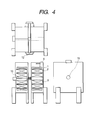
- the fourth embodiment of the present invention is shown in Fig. 4.
- the biosample is inserted into the apparatus from the side, and the measurement probe is inserted through the through hole 12 formed on the other side.
- the height of the apparatus can be lowered so that it can be used even when there is a limit in the height of the ceiling, whereby the operability is significantly improved and vibrations propagated from the floor to the apparatus can be reduced. Therefore, an economically effective system, which is superior in installability and maintenanceability, can be provided.
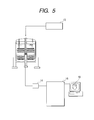
- the fifth embodiment of the present invention is shown in Fig. 5.
- the biosample 4 is sent to the sample being maintained in a living state by the use of a oxygen supply unit 13.
- the NMR signal is sent to the controller 15 via a preamplifier 14.
- Various types of pulse sequences are applied to receive the NMR signal.
- the pulse is emitted as needed, and the pulse sequence is combined with a gradient magnetic field and imaged, and then sent to the display 16. It is also possible to use the preamplifier 14 after being cooled to temperatures close to that of liquid nitrogen in order to reduce heat noise of the signal.
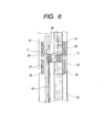
- Fig. 6 shows the structure of the detector probe according to the present invention in detail.
- the biosample 4 is a small animal.
- the biosample 4 is inserted into a glass tube of 1 to 30 mm in diameter having the equivalent properties as water, and disposed in the center of the magnetic field in the apparatus from below.
- Material of the solenoid detector coil 17 may be copper or superconducting wire. When superconducting wire is used, it is cooled generally to 4 to 20 K by helium gas 25. When copper wire is used, there is a case where it is maintained at ordinary temperatures.
- the combination of 3-axis gradient magnetic field coils 19, 20, 21, 22, 23, 24, can generate a desired magnetic field gradient in the desired direction, and used for imaging in combination with the pulse sequence.
- the detected signal is sent to the preamplifier via a lead 18.
- sensitivity is increased to three-fold that in the related art, thereby being superior in maintenanceability, and enabling the experiment of light irradiation described in Embodiment 2.
- sensitivity is increased to ten-fold that in the related art by forming the detector coil into a solenoid shape and providing the same a superconducting property, when it is put into practice with 900 MHz (21.1 T) for example, detection sensitivity that corresponds to 2.7GHz in the related art can be obtained, it can effectively realize detection sensitivity that was impossible to achieve in the related art.
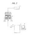
- the sixth embodiment of the present invention is shown in Fig. 7.
- the basic structure of the apparatus is identical to Embodiment 5 of the present invention.
- growth of protein is carried out in the magnetic field.
- Crystal is grown while solidifying protein 26 dissolved in the test tube.
- Conditions of crystal growth can be controlled by changing the flow rate of oxygen or the temperature conditions of the sample.
- the protein crystal of good quality can be grown up by observing the process of growth under such circumstances by means of supersensitive imaging with spatial resolutions in the order of 0.5 micron.
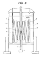
- FIG. 8 A typical construction of the NMR imaging apparatus of 600 MHz class in the related art is shown in Fig. 8 as a comparative example of the construction of the NMR apparatus in the present invention.
- the central magnetic field is 14.1 T.
- a birdcage receiving coil 27 and superconducting magnets 28, 29, 30 form a multi-layer hollow solenoid coil.
- the only way to improve sensitivity to the same level as the present invention in this detecting method is to increase the central magnetic field.
- the limit is 21 T.
- detection sensitivity is in the order of one-third the case of the present invention. Spatial resolution of image analysis is 40 ⁇ m, which is caused by insufficient uniformity of magnetic field and low sensitivity.
- the construction of the birdcage probe 27 in the related art is shown in Fig. 9 as a comparative example of the construction of the NMR apparatus in the present invention.
- a saddle type coil is used in the related art
- the same level of detection sensitivity as in Embodiment 1 of the present invention could not be obtained in a method combined with Comparative Example 1.
- the only way to improve sensitivity in this detecting method is to decrease the temperature.
- a method of utilizing superconducting technology is also proposed in the present circumstances, there arise problems of high costs and of maintenanceability.
- detection sensitivity is as low as one-third the solenoid detector coil of the present invention, and thus it was difficult to obtain a sufficient spectrum intensity required for imaging.
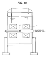
- the comparative example of the present invention is shown in Fig. 10.
- a known multi-purpose NMR solenoid coil generating uniform magnetic field in the horizontal direction in the known horizontal-type magnetic field arrangement was combined with the known birdcage detector coil in Comparative Example 2, and a test tube containing protein solution was inserted into the measuring portion through the communication hole formed in the horizontal direction.
- the nuclear magnetic resonance signal of generally 400 MHz was obtained by the magnetic field in the measuring portion, but the spatial nonuniformity that corresponds to the error of 20 Hz occurred in the magnetic field with the sample space of 10 mm in diameter and 20 mm in length.
- Nonuniformity of magnetic field per hour was 10 Hz/h.
- a comparative example of the present invention is shown in Fig. 11.
- a known multi- purpose NMR solenoid coil generating uniform magnetic field in the horizontal direction in the known horizontal-type magnetic field arrangement was combined with the known birdcage detector coil in Comparative Example 2 through the communication hole from the top of the apparatus to the measuring portion, and protein solution is inserted into a test tube. Since the measuring instrument was inserted from the top, the through hole was upsized to 200 mm in maximum diameter. As a consequent, the central magnetic field strength was lowered. Even when efforts were made to adjust the magnetic field strength, only the nuclear magnetic resonance signal of 300 MHz could be obtained in the center of the magnetic field at the maximum. Nonuniform magnetic field corresponding to the error of 10 Hz was observed in the sample space of 10 mm in diameter and 20 mm in length. These values are normal as a multi-purpose NMR apparatus, but accuracy was one digit lower for high resolution NMR imaging.
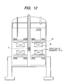
- FIG. 12 A comparative example of the present invention is shown in Fig. 12.
- Two known multi-purpose NMR solenoid coils that generate uniform magnetic fields in the vertical direction of 18 T-class were combined in the known horizontal-type magnetic field arrangement. Then, they are combined with the solenoid detector coil of the present invention through a communication hole of 70 mm in diameter formed from the top of the apparatus to the measuring portion, and a small animal was inserted therein. All the measuring instruments and solution sample are inserted from the top.
- the maximum magnetic field of each magnet was 18 T in the direction of axes of two magnetic systems.
- the time-based stability of the magnetic field was in the order of 0.001 ppm/h.
- the stationary magnetic field strength in the sample space was 7.5 T, and uniformity of the sample space magnetic field was not more than 100 ppm, which were the level that cannot be used for measurement as a high resolution NMR imaging apparatus.
- FIG. 13 A comparative example of the present invention is shown in Fig. 13.
- a detector coil 31 wound in the solenoid shape combined with a known high temperature superconducting bulk magnet 32 that generates magnetic fields in the vertical direction was used for constructing the NMR imaging measurement for small animals. It is characterized by the solenoid coil wound so as to be protruded significantly from the area of uniform magnetic field, which helps to recognize variations in magnetic flux in a wide range, but is poor in image measuring accuracy in comparison with the case in which the detector coil is disposed within the uniform magnetic field.
- the highest magnetic field of the magnet was 10 T, but the highest magnetic field in the sample space was 4T.
- Uniformity in the magnetic field was 200 to 500 ppm or less due to nonuniformity of the high temperature superconducting body.
- the time-based stability of the magnetic field was in the order of 20 to 100 ppm/h due to the magnetic flux creeping phenomenon of the high temperature superconducting body. As a consequent, it was the system that cannot be reached to the image resolution intended by the present invention at all.
- the nuclear magnetic resonance imaging that enables the interior of cells in a nondestructive manner can display its greatest force. Accordingly, what kind of roles (functions) the individual protein has on the scales of cells, organic tissues, or living organisms can be figured out, and thus the study of life science can significantly be advanced.
- the physical behavior of protein molecules can be brought out as well by analyzing the phase change process of crystallizing solution to a solid substance in detail. Therefore, the volume of a protein molecule at the moment when water is hydrated on a specific surface thereof can be estimated by examining the effects of pressure affected on the solubility of protein in a state in which the crystal is growing.
- the present invention analysis of interaction between proteins becomes possible.
- imaging with resolution not more than 1 micron becomes possible by supersensitive NMR measurement, which is three fold that in the related art.
- the required resonance frequency is at least 600 MHz, and when the central magnetic field is operated at 900 MHz that is the highest level in the current superconducting technology, the detection sensitivity corresponding to 2.7 GHz in the related art may be obtained, which may realize a supersensitive signal detection which was impossible in the related art.
- the functions of the structurally known protein in the living organisms and the control thereof, or applications of crystallization can effectively be promoted in the study of life science in this era.
- Optimal development fully utilizing the advanced biotechnology while enjoying support of molecular design combined with, for example, the calculated simulation, is necessary for creating industrial applications such as molecular motors or biocomputers.
- the costs and term of development can considerably be reduced.
- the ripple effect of such advantages affected on this country and thus on all humankind is incalculable.
- the NMR technology of the present invention improves the detection sensitivity as much as three-fold or more that in the related art, the accumulated time can be reduced to one-tenth, and thus imaging in the cell becomes possible.
- the affect of micrometal on the living bodies can effectively be investigated. More specifically, real-time follow up of the affects of metal element of the same concentration as in the living bodies on the existence of protein or the dynamic state of labeled protein or micronutrient in the living bodies by the use of the imaging method may be able to apply in a huge number of disorders involving micronutrient or protein in the living bodies, for example, development of medical treatment of Alzheimer, or early diagnosis of chronic or intractable diseases before showing the symptoms of the diseases (diabetes or Creutzfeldt-Jakob disease). Furthermore, according to the present measurement technology, maintenanceability and installability of the measuring instrument can significantly be improved, and thus it provides good benefits when introduced. Especially, even with the relatively limited scale of experimental equipment, high-quality data acquisition as in the large-scale experimental equipment of 900 MHz class may be realized.
Landscapes
- Physics & Mathematics (AREA)
- General Physics & Mathematics (AREA)
- Condensed Matter Physics & Semiconductors (AREA)
- Nuclear Medicine, Radiotherapy & Molecular Imaging (AREA)
- Radiology & Medical Imaging (AREA)
- Engineering & Computer Science (AREA)
- Signal Processing (AREA)
- General Health & Medical Sciences (AREA)
- High Energy & Nuclear Physics (AREA)
- Health & Medical Sciences (AREA)
- Electromagnetism (AREA)
- Magnetic Resonance Imaging Apparatus (AREA)
- Investigating Or Analyzing Materials By The Use Of Magnetic Means (AREA)
Applications Claiming Priority (2)
| Application Number | Priority Date | Filing Date | Title |
|---|---|---|---|
| JP2002132253A JP2003329756A (ja) | 2002-05-08 | 2002-05-08 | 超高感度核磁気共鳴イメージング装置 |
| JP2002132253 | 2002-05-08 |
Publications (2)
| Publication Number | Publication Date |
|---|---|
| EP1361455A2 true EP1361455A2 (de) | 2003-11-12 |
| EP1361455A3 EP1361455A3 (de) | 2004-08-25 |
Family
ID=29244101
Family Applications (1)
| Application Number | Title | Priority Date | Filing Date |
|---|---|---|---|
| EP02028840A Withdrawn EP1361455A3 (de) | 2002-05-08 | 2002-12-23 | Gerät für die bildgebende magnetische Resonanz mit besonders hoher Empfindlichkeit |
Country Status (3)
| Country | Link |
|---|---|
| US (3) | US6975118B2 (de) |
| EP (1) | EP1361455A3 (de) |
| JP (1) | JP2003329756A (de) |
Cited By (2)
| Publication number | Priority date | Publication date | Assignee | Title |
|---|---|---|---|---|
| GB2431048A (en) * | 2005-10-06 | 2007-04-11 | Bruker Biospin Gmbh | Superconducting magnet coil system with quench protection |
| CN110346397A (zh) * | 2019-08-05 | 2019-10-18 | 固安县朝阳生物科技有限公司 | 核磁共振多模块检测模体 |
Families Citing this family (20)
| Publication number | Priority date | Publication date | Assignee | Title |
|---|---|---|---|---|
| JP2003130937A (ja) * | 2001-10-24 | 2003-05-08 | Hitachi Ltd | 溶液用核磁気共鳴分析装置 |
| US20040041565A1 (en) * | 2002-05-08 | 2004-03-04 | Shigeru Kakugawa | NMR magnet device for solution analysis and NMR apparatus |
| JP3879584B2 (ja) * | 2002-05-08 | 2007-02-14 | 株式会社日立製作所 | Nmr分析装置 |
| JP3993127B2 (ja) * | 2003-04-24 | 2007-10-17 | 株式会社日立製作所 | Nmr装置用超電導プローブコイル |
| US7378844B2 (en) * | 2004-09-30 | 2008-05-27 | General Electric Company | Magnetic resonance system, receiver & method of generating detecting and digitizing analog MR signals solely within the MR shielded environment |
| JP4309854B2 (ja) | 2005-01-20 | 2009-08-05 | 株式会社日立製作所 | 低温プローブ及びそれを用いた核磁気共鳴分析装置 |
| JP4319650B2 (ja) | 2005-07-29 | 2009-08-26 | 株式会社日立製作所 | Nmr用低温プローブおよびnmr装置 |
| RU2008129669A (ru) * | 2005-12-20 | 2010-01-27 | Конинклейке Филипс Электроникс Н.В. (Nl) | Магнитно-резонансный сканер с градиентной катушкой, расположенной рядом с обмотками основного магнита |
| EP2592136B1 (de) * | 2006-02-14 | 2022-04-20 | Aspect AI Ltd. | Reaktor auf MRD-Basis |
| JP4787033B2 (ja) * | 2006-02-15 | 2011-10-05 | 株式会社日立製作所 | 核磁気共鳴信号用ソレノイドコイル及び核磁気共鳴信号取得装置 |
| US9494540B2 (en) | 2006-08-21 | 2016-11-15 | Aspect Ai Ltd. | System and method for a nondestructive on-line testing of samples |
| WO2008066146A1 (fr) | 2006-11-30 | 2008-06-05 | Japan Science And Technology Agency | Dispositif d'imagerie par resonance magnétique nucléaire, et système d'imagerie et procédé d'imagerie utilisant un tel dispositif |
| JP4861149B2 (ja) * | 2006-12-08 | 2012-01-25 | 株式会社日立製作所 | 核磁気共鳴装置 |
| US8035385B2 (en) * | 2007-11-22 | 2011-10-11 | Kabushiki Kaisha Toshiba | MRI system and RF coil with enhanced cooling in vicinty of included circuit elements |
| JP5472896B2 (ja) * | 2007-11-22 | 2014-04-16 | 株式会社東芝 | 磁気共鳴装置 |
| JP2011518409A (ja) * | 2008-03-30 | 2011-06-23 | ヒルズ, インコーポレイテッド | 超伝導ワイヤおよびケーブルならびにその製造方法 |
| JP5582756B2 (ja) * | 2008-11-28 | 2014-09-03 | 株式会社東芝 | 高周波コイルユニットおよび磁気共鳴診断装置 |
| US8807084B2 (en) | 2010-09-30 | 2014-08-19 | Aspect Imaging Ltd. | MRI device with a plurality of individually controllable entry ports and inserts therefor |
| US10292617B2 (en) | 2010-09-30 | 2019-05-21 | Aspect Imaging Ltd. | Automated tuning and frequency matching with motor movement of RF coil in a magnetic resonance laboratory animal handling system |
| JP6341535B2 (ja) * | 2014-04-30 | 2018-06-13 | 株式会社エム・アール・テクノロジー | 画像撮像ユニット |
Family Cites Families (41)
| Publication number | Priority date | Publication date | Assignee | Title |
|---|---|---|---|---|
| US3329890A (en) * | 1964-08-17 | 1967-07-04 | Varian Associates | Gyromagnetic resonance apparatus |
| US3450952A (en) * | 1965-08-30 | 1969-06-17 | Varian Associates | Superconducting magnet apparatus |
| JPS4911574B1 (de) * | 1970-08-17 | 1974-03-18 | ||
| US3764892A (en) * | 1971-01-04 | 1973-10-09 | Southwest Res Inst | Spectroscopic apparatus |
| US3771055A (en) * | 1972-03-17 | 1973-11-06 | Varian Associates | Double nuclear magnetic resonance coil |
| US4628263A (en) * | 1983-06-13 | 1986-12-09 | Jeol Ltd. | Nuclear magnetic resonance spectrometer |
| JPS61115958U (de) * | 1984-12-30 | 1986-07-22 | ||
| US4788500A (en) * | 1985-08-14 | 1988-11-29 | Brigham & Women's Hospital | Measurement of capillary flow using nuclear magnetic resonance |
| US4716367A (en) * | 1986-08-15 | 1987-12-29 | Brigham & Women's Hospital | Creation and use of a moving reference frame for NMR imaging of flow |
| DE3907927A1 (de) * | 1989-03-11 | 1990-09-20 | Bruker Analytische Messtechnik | Magnetsystem |
| US5276398A (en) * | 1992-06-01 | 1994-01-04 | Conductus, Inc. | Superconducting magnetic resonance probe coil |
| US6159402A (en) * | 1992-08-04 | 2000-12-12 | Valyi; Emery I. | Process for forming a color coated article |
| GB9324596D0 (en) * | 1993-11-30 | 1994-01-19 | Oxford Analytical Instr Ltd | Variable temperature nmr probe |
| JPH07240310A (ja) * | 1994-03-01 | 1995-09-12 | Mitsubishi Electric Corp | 核磁気共鳴分析装置用超電導マグネット |
| JPH07333311A (ja) * | 1994-06-10 | 1995-12-22 | Hitachi Ltd | 核磁気共鳴装置 |
| EP0738897B1 (de) * | 1995-03-25 | 2000-08-09 | Bruker AG | HF-Empfangsspulenanordnung für NMR-Spektrometer |
| JP3505566B2 (ja) * | 1995-06-23 | 2004-03-08 | 独立行政法人農業・生物系特定産業技術研究機構 | 生理状態解析装置および方法 |
| US5696476A (en) * | 1995-07-31 | 1997-12-09 | General Electric Company | Open architecture magnetic resonance imaging superconducting magnet assembly |
| US5552709A (en) * | 1995-10-17 | 1996-09-03 | Varian Associates, Inc. | NMR sample cell |
| DE19548272C1 (de) * | 1995-12-22 | 1997-05-28 | Bruker Analytische Messtechnik | Supraleitende NMR-Magnetanordnung |
| JP2002034947A (ja) * | 1997-10-24 | 2002-02-05 | Hitachi Ltd | マグネット装置、および、これを用いたmri装置 |
| US5986453A (en) * | 1997-11-07 | 1999-11-16 | Varian, Inc. | AC magnetic susceptibility control of superconducting materials in nuclear magnetic resonance (NMR) probes |
| US6201392B1 (en) * | 1997-11-07 | 2001-03-13 | Varian, Inc. | Coplanar RF probe coil arrangement for multifrequency excitation |
| US6198281B1 (en) * | 1997-11-12 | 2001-03-06 | The Research Foundation Of State University Of New York | NMR spectroscopy of large proteins |
| US6163154A (en) * | 1997-12-23 | 2000-12-19 | Magnetic Diagnostics, Inc. | Small scale NMR spectroscopic apparatus and method |
| JPH11248810A (ja) * | 1998-02-27 | 1999-09-17 | Rikagaku Kenkyusho | 核磁気共鳴装置 |
| GB9808333D0 (en) * | 1998-04-18 | 1998-06-17 | Inst Of Food Research | A cyclic field-cycling spectrometer |
| US6159444A (en) * | 1998-09-11 | 2000-12-12 | The Regents Of The University Of California | NMR/MRI with hyperpolarized gas and high Tc SQUID |
| DE19956977A1 (de) * | 1998-11-27 | 2000-07-20 | Jeol Ltd | NMR-Sonde |
| CA2369935A1 (en) * | 1999-04-06 | 2000-10-12 | The Uab Research Foundation | Method for screening crystallization conditions in solution crystal growth |
| JP4074042B2 (ja) * | 2000-03-17 | 2008-04-09 | 独立行政法人物質・材料研究機構 | 高磁場で磁場均一度の高い超電導磁石装置 |
| US6788061B1 (en) * | 2000-08-01 | 2004-09-07 | The Board Of Trustees Of The University Of Illinois | Microcoil based micro-NMR spectrometer and method |
| JP3497826B2 (ja) * | 2001-01-12 | 2004-02-16 | シーメンス アクチエンゲゼルシヤフト | 磁気共鳴撮像装置 |
| US6646836B2 (en) * | 2001-03-01 | 2003-11-11 | Kabushiki Kaisha Kobe Seiko Sho | Superconducting magnet apparatus in persistent mode |
| DE10118835C2 (de) * | 2001-04-17 | 2003-03-13 | Bruker Biospin Ag Faellanden | Supraleitende Resonatoren für Anwendungen in der NMR |
| US6650116B2 (en) * | 2001-04-20 | 2003-11-18 | Regents Of The University Of Minnesota | Method and system for NMR using adiabatic RF pulses producing spatially quadratic phase |
| GB0120697D0 (en) * | 2001-08-24 | 2001-10-17 | Coated Conductors Consultancy | Superconducting coil fabrication |
| JP2003130937A (ja) * | 2001-10-24 | 2003-05-08 | Hitachi Ltd | 溶液用核磁気共鳴分析装置 |
| US6777938B2 (en) * | 2001-11-15 | 2004-08-17 | Bruker Biospin Gmbh | NMR magnet coil system with separate superconducting short-circuited regions for drift compensation as well as method for operation thereof |
| JP3879584B2 (ja) * | 2002-05-08 | 2007-02-14 | 株式会社日立製作所 | Nmr分析装置 |
| JP4090389B2 (ja) * | 2003-06-10 | 2008-05-28 | 株式会社日立製作所 | 核磁気共鳴装置 |
-
2002
- 2002-05-08 JP JP2002132253A patent/JP2003329756A/ja active Pending
- 2002-12-23 US US10/326,085 patent/US6975118B2/en not_active Expired - Fee Related
- 2002-12-23 EP EP02028840A patent/EP1361455A3/de not_active Withdrawn
-
2003
- 2003-09-08 US US10/656,185 patent/US6937019B2/en not_active Expired - Fee Related
-
2005
- 2005-06-28 US US11/167,185 patent/US20050248349A1/en not_active Abandoned
Cited By (4)
| Publication number | Priority date | Publication date | Assignee | Title |
|---|---|---|---|---|
| GB2431048A (en) * | 2005-10-06 | 2007-04-11 | Bruker Biospin Gmbh | Superconducting magnet coil system with quench protection |
| US7330341B2 (en) | 2005-10-06 | 2008-02-12 | Bruker Biospin Gmbh | Superconducting magnet coil system with quench protection |
| GB2431048B (en) * | 2005-10-06 | 2009-08-12 | Bruker Biospin Gmbh | Superconducting magnet coil system with quench protection |
| CN110346397A (zh) * | 2019-08-05 | 2019-10-18 | 固安县朝阳生物科技有限公司 | 核磁共振多模块检测模体 |
Also Published As
| Publication number | Publication date |
|---|---|
| US6937019B2 (en) | 2005-08-30 |
| JP2003329756A (ja) | 2003-11-19 |
| US20040046556A1 (en) | 2004-03-11 |
| EP1361455A3 (de) | 2004-08-25 |
| US20030210052A1 (en) | 2003-11-13 |
| US20050248349A1 (en) | 2005-11-10 |
| US6975118B2 (en) | 2005-12-13 |
Similar Documents
| Publication | Publication Date | Title |
|---|---|---|
| US6975118B2 (en) | Supersensitive nuclear magnetic resonance micro imaging apparatus | |
| US7492159B2 (en) | Nuclear magnetic resonance spectrometer for liquid-solution | |
| US8723522B2 (en) | Superconductor RF coil array | |
| US8731635B2 (en) | Coils for magnetic resonance spectroscopy and imaging of human breast | |
| US20040222796A1 (en) | Solid-state nuclear magnetic resonance probe | |
| US9285443B2 (en) | MSC-SelMQC method for simultaneous mapping of polyunsaturated fatty acids, lactate and choline in high fat tissues | |
| WO2010123939A2 (en) | Cryogenically cooled superconductor rf head coil array and head-only magnetic resonance imaging (mri) system using same | |
| Goloshevsky et al. | Development of low field nuclear magnetic resonance microcoils | |
| JP2006521551A (ja) | 受信コイルアレイを使って多数のサンプルを同時に分析するための核磁気共鳴装置 | |
| Borisjuk et al. | Perspectives: The look insight–magnet resonance imaging (MRI) of the inner life of plants | |
| CA2339316C (en) | Mini-invasive nuclear magnetic resonance spectroscopy catheter probe | |
| JP2007090089A (ja) | 超高感度核磁気共鳴イメージング装置 | |
| EP1477822A1 (de) | Kernspinresonanzspektrometer für flüssige Lösungen | |
| Zhou et al. | A Chip-based Miniature MRI Platform with Integrated PDMS-PCB Coil Frontend for Microlitre-volume Sample Analysis | |
| JP4319641B2 (ja) | Nmr装置及びその測定方法 | |
| EP1555538A1 (de) | Verfahren der schnellen multidimensionalen NMR-Spektroskopie | |
| JP2007114209A (ja) | 溶液用核磁気共鳴分析装置 | |
| Massin et al. | Magnetic resonance imaging using microfabricated planar coils |
Legal Events
| Date | Code | Title | Description |
|---|---|---|---|
| PUAI | Public reference made under article 153(3) epc to a published international application that has entered the european phase |
Free format text: ORIGINAL CODE: 0009012 |
|
| AK | Designated contracting states |
Kind code of ref document: A2 Designated state(s): AT BE BG CH CY CZ DE DK EE ES FI FR GB GR IE IT LI LU MC NL PT SE SI SK TR |
|
| AX | Request for extension of the european patent |
Extension state: AL LT LV MK RO |
|
| PUAL | Search report despatched |
Free format text: ORIGINAL CODE: 0009013 |
|
| AK | Designated contracting states |
Kind code of ref document: A3 Designated state(s): AT BE BG CH CY CZ DE DK EE ES FI FR GB GR IE IT LI LU MC NL PT SE SI SK TR |
|
| AX | Request for extension of the european patent |
Extension state: AL LT LV MK RO |
|
| 17P | Request for examination filed |
Effective date: 20050223 |
|
| AKX | Designation fees paid |
Designated state(s): CH DE GB LI |
|
| RBV | Designated contracting states (corrected) |
Designated state(s): CH DE GB LI |
|
| 17Q | First examination report despatched |
Effective date: 20091217 |
|
| STAA | Information on the status of an ep patent application or granted ep patent |
Free format text: STATUS: THE APPLICATION IS DEEMED TO BE WITHDRAWN |
|
| 18D | Application deemed to be withdrawn |
Effective date: 20100629 |