EP1360397B2 - Procede et palette pour produire une piece prefabriquee en beton precise - Google Patents
Procede et palette pour produire une piece prefabriquee en beton precise Download PDFInfo
- Publication number
- EP1360397B2 EP1360397B2 EP02706697A EP02706697A EP1360397B2 EP 1360397 B2 EP1360397 B2 EP 1360397B2 EP 02706697 A EP02706697 A EP 02706697A EP 02706697 A EP02706697 A EP 02706697A EP 1360397 B2 EP1360397 B2 EP 1360397B2
- Authority
- EP
- European Patent Office
- Prior art keywords
- accordance
- foregoing
- pallet
- shuttering
- unfinished part
- Prior art date
- Legal status (The legal status is an assumption and is not a legal conclusion. Google has not performed a legal analysis and makes no representation as to the accuracy of the status listed.)
- Expired - Lifetime
Links
- 238000000034 method Methods 0.000 title claims abstract description 42
- 238000004519 manufacturing process Methods 0.000 title claims abstract description 36
- 239000011178 precast concrete Substances 0.000 title claims abstract description 31
- 229910000831 Steel Inorganic materials 0.000 claims description 79
- 239000010959 steel Substances 0.000 claims description 79
- 239000004567 concrete Substances 0.000 claims description 22
- 238000012545 processing Methods 0.000 claims description 22
- 238000003754 machining Methods 0.000 claims description 14
- 230000002787 reinforcement Effects 0.000 claims description 13
- 239000000872 buffer Substances 0.000 claims description 10
- 238000001035 drying Methods 0.000 claims description 9
- 238000003860 storage Methods 0.000 claims description 6
- 238000004140 cleaning Methods 0.000 claims description 5
- 230000006835 compression Effects 0.000 claims description 3
- 238000007906 compression Methods 0.000 claims description 3
- 239000000835 fiber Substances 0.000 claims description 3
- 238000000227 grinding Methods 0.000 claims description 3
- 239000000463 material Substances 0.000 claims description 3
- 238000006073 displacement reaction Methods 0.000 claims description 2
- 238000009416 shuttering Methods 0.000 claims 20
- 238000005520 cutting process Methods 0.000 claims 2
- 230000003014 reinforcing effect Effects 0.000 claims 2
- 239000011248 coating agent Substances 0.000 claims 1
- 238000000576 coating method Methods 0.000 claims 1
- 238000005304 joining Methods 0.000 claims 1
- 241001669679 Eleotris Species 0.000 abstract 1
- 238000009415 formwork Methods 0.000 description 43
- 238000010276 construction Methods 0.000 description 7
- 239000007787 solid Substances 0.000 description 7
- 238000009434 installation Methods 0.000 description 6
- 210000001520 comb Anatomy 0.000 description 4
- 238000012805 post-processing Methods 0.000 description 4
- 229910001294 Reinforcing steel Inorganic materials 0.000 description 3
- 239000000969 carrier Substances 0.000 description 3
- 238000003801 milling Methods 0.000 description 3
- 238000003780 insertion Methods 0.000 description 2
- 230000037431 insertion Effects 0.000 description 2
- 238000004904 shortening Methods 0.000 description 2
- 230000020347 spindle assembly Effects 0.000 description 2
- 238000005266 casting Methods 0.000 description 1
- 239000007795 chemical reaction product Substances 0.000 description 1
- 150000001875 compounds Chemical class 0.000 description 1
- 238000000205 computational method Methods 0.000 description 1
- 230000006837 decompression Effects 0.000 description 1
- 230000003292 diminished effect Effects 0.000 description 1
- 230000000694 effects Effects 0.000 description 1
- 239000012467 final product Substances 0.000 description 1
- 230000002045 lasting effect Effects 0.000 description 1
- 230000002093 peripheral effect Effects 0.000 description 1
- 239000011295 pitch Substances 0.000 description 1
- 230000036316 preload Effects 0.000 description 1
- 238000000926 separation method Methods 0.000 description 1
- 238000007493 shaping process Methods 0.000 description 1
- 239000006228 supernatant Substances 0.000 description 1
Images

Classifications
-
- B—PERFORMING OPERATIONS; TRANSPORTING
- B28—WORKING CEMENT, CLAY, OR STONE
- B28B—SHAPING CLAY OR OTHER CERAMIC COMPOSITIONS; SHAPING SLAG; SHAPING MIXTURES CONTAINING CEMENTITIOUS MATERIAL, e.g. PLASTER
- B28B11/00—Apparatus or processes for treating or working the shaped or preshaped articles
- B28B11/08—Apparatus or processes for treating or working the shaped or preshaped articles for reshaping the surface, e.g. smoothing, roughening, corrugating, making screw-threads
- B28B11/0863—Apparatus or processes for treating or working the shaped or preshaped articles for reshaping the surface, e.g. smoothing, roughening, corrugating, making screw-threads for profiling, e.g. making grooves
-
- B—PERFORMING OPERATIONS; TRANSPORTING
- B28—WORKING CEMENT, CLAY, OR STONE
- B28B—SHAPING CLAY OR OTHER CERAMIC COMPOSITIONS; SHAPING SLAG; SHAPING MIXTURES CONTAINING CEMENTITIOUS MATERIAL, e.g. PLASTER
- B28B23/00—Arrangements specially adapted for the production of shaped articles with elements wholly or partly embedded in the moulding material; Production of reinforced objects
- B28B23/02—Arrangements specially adapted for the production of shaped articles with elements wholly or partly embedded in the moulding material; Production of reinforced objects wherein the elements are reinforcing members
- B28B23/04—Arrangements specially adapted for the production of shaped articles with elements wholly or partly embedded in the moulding material; Production of reinforced objects wherein the elements are reinforcing members the elements being stressed
- B28B23/06—Arrangements specially adapted for the production of shaped articles with elements wholly or partly embedded in the moulding material; Production of reinforced objects wherein the elements are reinforcing members the elements being stressed for the production of elongated articles
-
- E—FIXED CONSTRUCTIONS
- E01—CONSTRUCTION OF ROADS, RAILWAYS, OR BRIDGES
- E01B—PERMANENT WAY; PERMANENT-WAY TOOLS; MACHINES FOR MAKING RAILWAYS OF ALL KINDS
- E01B3/00—Transverse or longitudinal sleepers; Other means resting directly on the ballastway for supporting rails
- E01B3/28—Transverse or longitudinal sleepers; Other means resting directly on the ballastway for supporting rails made from concrete or from natural or artificial stone
- E01B3/32—Transverse or longitudinal sleepers; Other means resting directly on the ballastway for supporting rails made from concrete or from natural or artificial stone with armouring or reinforcement
- E01B3/34—Transverse or longitudinal sleepers; Other means resting directly on the ballastway for supporting rails made from concrete or from natural or artificial stone with armouring or reinforcement with pre-tensioned armouring or reinforcement
-
- E—FIXED CONSTRUCTIONS
- E01—CONSTRUCTION OF ROADS, RAILWAYS, OR BRIDGES
- E01B—PERMANENT WAY; PERMANENT-WAY TOOLS; MACHINES FOR MAKING RAILWAYS OF ALL KINDS
- E01B1/00—Ballastway; Other means for supporting the sleepers or the track; Drainage of the ballastway
- E01B1/002—Ballastless track, e.g. concrete slab trackway, or with asphalt layers
Definitions
- the present invention relates to a method for producing a precise precast concrete part, in particular in the form of a threshold or a slab of a fixed track for rail-guided vehicles and a pallet for producing a prestressed precast concrete part with a formwork and a tensioning device for tensioning wires.
- precast concrete parts solid roadways for rail-guided vehicles, wall elements or other supports or supports are produced as precast concrete parts.
- precast concrete parts no particular precision in the dimensions of the part is required. The usual, achievable in the concrete trade tolerances are sufficient here. If other components are mounted on the precast concrete parts, which must comply with very tight tolerances, this is usually done with adjustment so that resulting from the concrete inaccuracies can be compensated.
- rail fasteners are used at the individual bases, which make the rail adjustable in several directions in order to comply with the tight tolerances between the individual rails can.
- Object of the present invention is thus to provide a method and an apparatus with which precast concrete parts can be produced, which allow tighter than usual tolerances for body parts. It is thus the cost of manufacturing, equipment and installation of concrete components and the rails and their attachment significantly reduced.
- the precast concrete part is first prepared in a formwork as a blank in a method for producing a precise precast concrete part, in particular in the form of a threshold or slab for a fixed track for rail-guided vehicles. It is then cured in an advantageous embodiment of the invention by storage for several days and then, at least on the functionally relevant parts, if necessary, applied material, for example plastic, and / or machined to the predetermined level. Due to the storage lasting several days, the prefabricated concrete element hardens to a great extent, as a result of which it creeps and shrinks to almost its final state. As a result, a component is obtained which is largely dimensionally stable and thus will hardly change even when later used on a construction site. On this basis, the post-processing of the functionally relevant bodies is carried out. The post-processing can also be done on the now mounted rail fasteners, which in particular, when the component is cured, can also be edited very accurately.
- the blank rail supports which are processed according to the individual requirements of the precast concrete part to the required in the later route, predetermined level. It thus components are obtained, which may be provided for a specific location in a route.
- relatively simple standard components can be used, which do not differ from each other. This has the advantage that when replacing rails or rail fasteners no consideration for the specific site must be taken and therefore any parts used or can be interchanged. An individual processing of the fasteners is not necessary.
- the machined part will retain the machined dimension. If subsequently other components, such as rails mounted on the fixed track, so these are very precise to attach to the component.
- solid lanes can be designed so that the functionally relevant surfaces are relatively small. It lends itself here, for example, to train the solid lane with hump, which represent the bases for the tracks. Thus, only these interpolation points must be processed.
- the remaining precast concrete part can be within a tolerance range, as is customary for the production of precast concrete parts.
- an individual precast concrete part can be produced by a corresponding processing of the functionally relevant points. It is thus possible to realize at fixed lanes, which are composed of a plurality of rectilinear panels, by machining the corresponding bases also radii.
- the blank of the precast concrete part is produced in circulation production. In this way it can be ensured that an always constant precision of the blank is guaranteed, whereby the machining can then be carried out under the same conditions. The precision of the end part can thus be guaranteed.
- a variety of individual finished parts can be made from standardized blanks.
- a substantially cost-effective production process is selected by the circulation production.
- the components can be produced in a multi-shift operation, wherein during the drying of the components already other shapes can be prepared and filled again.
- the blank and its formwork and / or a clamping device for prestressing steels of the blank is transported during the manufacture of the blank on movable pallets.
- all production-relevant components for the blank are arranged on the movable pallet and can thus go through the manufacturing process.
- the circulation production is divided into different processing stations.
- a cleaning station, a dowel and spindle mounting station for the slab of the slab, a reinforcement station, a tensioning station, a concreting station with or without a compression station, a drying chamber, a decompression and deswelling station and / or a blank removal station are provided.
- the pallet located there is processed and prepared accordingly, in order to finally allow the blank to be produced as a final product.
- Each individual station specializes in one or more specific activities. It can therefore also be advantageously provided that robots are provided in each station, which can perform all or a large part of the required work. In order to avoid that it is not possible to continue working at individual stations because there are standstills at other stations or longer work periods are required there, it is advantageous if buffers are provided between two stations in which the movable pallets can be temporarily stored.
- a part of the reinforcement arranged in the blank is prestressed.
- a very stable blank is obtained, which remains largely dimensionally stable during installation on the construction site and during later use and can absorb high loads.
- the reinforcement in particular in the case of slabs of a fixed carriageway in the transverse and longitudinal direction of the blank is arranged. Typical dimensions for slabs of a fixed carriageway are lengths of approx. 6.50 m and widths between 2.40 m and 3 m.
- the prestressing steels Due to the short lengths of the prestressing steels, a precise and, with regard to the individual prestressing steels, substantially uniform prestressing is required in order to be able to produce a uniformly stable component. In addition, it is necessary that the formwork of the blank and thus the shape of the component is not changed by the bias. It is therefore provided according to the invention that the prestressing steels are clamped independently of the formwork or formwork. As a result, in turn, a very precise blank and thus also obtain a very precise end product, since the bias is not introduced into the formwork, but on their own specially provided biasing devices. The formwork thus has to absorb only the concrete forces and can thus be performed in the usual way.
- the tension can also be supported on the formwork. This is sufficient if no high demands are placed on the peripheral design of the components.
- prestressing steels In order to apply the most uniform clamping force on the prestressing steels, it is advantageous if several prestressing steels are tensioned simultaneously. If a plurality of prestressing steels are connected to one another by means of a displacement and / or force compensation device, a uniform tension of the prestressing steels is made possible.
- New and inventive is that the prestressing steels are combined into sections and the sections are stretched individually or in groups or together or relaxed. As a result, at least individual areas are each provided with the same clamping force, whereby the blank can be made very uniform and stable.
- the side formwork and then the bottom formwork are removed from the blank for removal.
- the side formwork and then the bottom formwork are removed from the blank for removal.
- the blanks can be stored vertically, for example, for curing.
- the blank is advantageously transported by means of a removal cart in the Aushärtlager and later from Aushärtlager to a finishing station.
- Such stationary machines can be designed for example in gantry design and guarantee a particularly precise machining of the components.
- the components can be stored defined for processing according to their subsequent mounting position and edited in this situation. But it can also be calculated by computational methods, the later installation position in relation to the actual processing position and be made with the computer-controlled processing machine, the corresponding processing.
- the machining which will often be machining, will be carried out on the later contact surfaces of the rail or rail fastening and / or on centering points of the fixed carriageway. At the centering the connection to other fixed carriageway slabs is provided, so that a total of a defined rail bed, which is composed of a plurality of individual plates, arises.
- the rail fasteners and possibly also the rails are already mounted in the production hall, as soon as possible after machining on the fixed track.
- the complete panel can then be delivered to the construction site and installed at the intended location.
- the clamping device is mounted independently of the formwork. This makes it possible to create a blank, which offers the best conditions for later processing to create very precise dimensions and very tight tolerances.
- the demoulding and clamping of the blank is independently feasible.
- the clamping device is constructed such that it has at least one pressure support and at least one pulling device.
- the pressure support is independent of the formwork and therefore suitable to absorb the tensile forces acting on the prestressing steels. It is particularly simple in construction when the pulling device is rotatably mounted around the pressure support.
- At least one tension rod is arranged at one end of the pulling device and at least one fastening device for prestressing steel is arranged at the other end, then by means of the pulling device a rotation about the pressure support, which between the pulling device and the fastening device for the Prestressing steels is arranged, the force on the prestressing steels are carried out very advantageous.
- the fastening device be tensioned and locked by means of one or more clamping units, in particular by means of a hydraulic device.
- the clamping unit can then be removed again from the fastening device and used for the next clamping operation.
- the fastening device is a comb in which a plurality of prestressing steels can be suspended.
- the tension of the prestressing steels is then effected by moving the comb in the direction of the longitudinal axis of the prestressing steels, whereby the prestressing steels are stretched.
- the prestressing steels try to relax and thus bring a compressive stress in the concrete slab.
- the fastening device or the comb is rotatably mounted on the pulling device.
- the prestressing steels are upset at the ends and thus form a broadening.
- This broadening creates a positive connection between the reinforcing steel and the comb.
- an automatic hooking the prestressing steels in the comb is very easy to implement, since the prestressing steels must be placed only in one direction over the openings of the comb.
- the combs which are each arranged at one end of the prestressing steels, moved away from each other and thus cause the tension of the prestressing steels.
- the formwork can be equipped with various inserts.
- the inserts which can optionally be inserted into the basic formwork, are each designed so that they are suitable for a particular method of fastening the rails.
- the inserts may be designed such that they divide the formwork into several components.
- the side mold or parts thereof are removable from the bottom formwork.
- Another advantage here is that the insertion of the prestressing steels in the combs can be done automatically. Only after the insertion of the steels, a part of the side molds is fixed, whereby the shaping of the blank is effected.
- the side molds have corresponding recesses or pitches, so that the prestressing steels can be passed through the side formwork. It is particularly advantageous, as has already been explained above, if the formwork is in each case independent of the tensioning device and thus can also be grown or dismounted independently thereof.
- the pallet for circulation production advantageous, it is provided that it has rails or rollers. As a result, a movement of the pallet from station to station of the circulation production is very easy to implement.
- FIG. 1 are the various stations of the invention circulation production 1 for the production of precise precast concrete elements, in particular made of fiber concrete.
- a pallet 20 is fed to a first buffer 2 via conventional conveyors. From the buffer 2, the pallet 20 enters a cleaning station 3. Here, the formwork and, where appropriate, the clamping device is cleaned to ensure safe operation.
- the Cleaning station 3 are for this purpose, for example, vacuum cleaners available, which are advantageously operated by means of robots and clean the pallet 20.
- the dowel or spindle assembly is then performed in the station 4.
- the dowels and spindles are required in particular in a slab of a fixed track for rail-guided vehicles. By means of the spindles, the position of the plate is later aligned on the construction site or for processing. About the dowels, the rails or rail fasteners to guide the vehicle are mounted on the plate. Also in this station, the dowel and spindle assembly is largely feasible by means not shown robot.
- the pallet 20 From the buffer 2, the pallet 20 enters the first reinforcement station 5.
- different reinforcements are required.
- a part of the reinforcement for example mats or prestressing steels, which are designed in particular for slabs of fixed carriageways, are inserted into the formwork.
- the transverse thereto inserted prestressing steels such as threaded rods, can be inserted.
- a further buffer 2 is arranged between the two reinforcement stations 5.
- the prestressing steels In the subsequent tensioning station 6 hydraulic devices are provided with which the prestressing steels can be biased.
- the prestressed steels are fixed in the tensioning station 6, so that the example hydraulic bias after fixing the prestressing steels can be removed again and can be used for the next pallet 20 or next station.
- the tension of the steels can be done individually. Preferably, however, the tension will be at least section wise, and it may also be advantageous to tension several sections simultaneously. As a result, the clamping of all prestressing steels can be done faster than if this happens one after the other, so that if necessary, the cycle time of a pallet can be reduced.
- a further buffer 2 is approached by the pallet 20.
- the pallet 20 remains in the buffer 2 until the next station has become free again.
- the formwork with concrete such as fiber concrete, filled and optionally compacted, whereby the actual component is created.
- the pallet is moved into a drying chamber 9.
- a lift 8, 8 'at the beginning and at the end of the drying chamber 9 is arranged in each case.
- the pallets 20 are moved to different levels of the drying chamber 9, so that a large number of pallets 20 may be in circulation at the same time and a large number of precast concrete parts can be made simultaneously.
- the pallet 20 is removed from the drying chamber 9 via the lift 8 'and fed to a demoulding and relaxation station 10.
- the relaxation of the prestressing steels and the demolding is carried out simultaneously.
- the plate of the fixed carriageway is completely removed from the pallet and placed on a dump truck 12. If necessary, the built-in spindle, for example, 20mm is turned up here to be cleaned later. Subsequently, in a station 18, the separation of the protruding prestressing steel ends and the cleaning of the spindles.
- the removal cart 12 brings the plate into a tilting station 13, in which the plate is rotated, for example, by 90 ° and parked in a warehouse.
- the concrete hardens, causing it to creep and shrink and take on its final dimensions largely.
- the concrete part has largely reached its final dimensions and can be reworked.
- it is again placed on a trolley 12 via the tilting station 13 and fed to a further processing station 15.
- the plate is spindled for this purpose. This means that the plate is aligned according to their subsequent installation position in the fixed lane.
- This processing station 16 may include, for example, a concrete milling machine, drill or a grinding machine, with which the corresponding points of the blank are machined precisely or in shape or prepared for assembly.
- a concrete milling machine drill or a grinding machine, with which the corresponding points of the blank are machined precisely or in shape or prepared for assembly. The fact that the plate is cured causes the processing of the plate, that even in the later installation position, the dimensions achieved here can be maintained.
- the processing of the plate may for example also include the milling of recesses for guides, which are used at the ends of the plates.
- the guides which for example have a trapezoidal cross-section and are made of steel, overlap two plates and thus allow an exact alignment of the plates to each other.
- three such guides on the top, bottom and / or side surfaces of the plate have proven to be advantageous to secure positioning of the plates in the x-, y- and z-direction each other as long maintain until the position of the plates is finally fixed, for example by a bottom casting.
- By a corresponding angular arrangement of the recesses to the longitudinal axis of the plate it is possible to provide a polygon laying of the plates.
- the precast concrete part of a last station namely an assembly station 17 is supplied.
- the assembly station 17 the rail fasteners and possibly even the rails themselves are mounted on the plate.
- This pre-assembled plate can be processed very quickly later on the construction site, as adjustment can largely be dispensed with after the specifications which were given to the individual individual plate could already be taken into account during machining and assembly.
- the plate made individually for a special slot in the fixed carriageway is optionally numbered and transported via a transport cart 12 a warehouse or directly to the site.
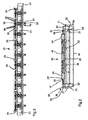
- FIG. 2 a front view of a pallet 20 is shown.
- the pallet 20 is constructed on carriers 21 and rails 22.
- the side wall 24 of the front side various undercuts are provided in order to carry out the connection of adjacent plates of the fixed carriageway.
- the side mold 24 is, for example, with devices not shown hinged or removable from the bottom mold, so that the removal of the subsequent blank is easily possible.
- Each tensioning device consists of a pressure support 31 and a traction device 32.
- the traction device 32 is rotatably mounted about a pivot point 33 of the pressure support 31.
- a tension rod 34 is arranged below the pressure support 31 below the pressure support 31 below the pressure support 31 below the pressure support 31.
- a second pulling device 32 ' is fixed to the pressure support 31. With her, a spindle 40 and a nut 39 cooperates.
- the effective length of the spindle 40 can be shortened.
- the shortening is done for example by means of a hydraulic device which acts on the spindle 40 and shortens its effective length.
- the pulling device 32 is rotated about the pivot point 33 and the prestressing steel 35 and the tension rod 34 is stretched.
- the shortened spindle 40 is fixed by means of the nut 39.
- the second pulling device 32 ' may also be rotatable, equal or similar to the attachment of the pulling device 32 to the pressure support 31.
- the prestressing steels 35 are connected to the upper end of the drawbar 32 and 32 '.
- the connection of the prestressing steels 35 takes place in the present embodiment by means of a comb 36, which is connected via a pivot point 37 with the upper end of the pulling device 32.
- the prestressing steels 35 are preferably hung in the comb 36 via an upsetting. But there are also other cross-sectional changes already described above possible.
- the tensioning device 30 acts independently of the formwork 23, 24, 24 ', so that a deformation of the formwork 23, 24, 24' does not occur when the tension is applied.
- the tension is essentially supported by the pressure support 31, which is fastened to the frame of the pallet 20.
- the pressure support 31 is formed so stable that a deformation of the pallet 20 is also avoided.
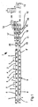
- FIG. 3 a side view of a pallet 20 is shown.
- the skeleton of the pallet 20 consists of the carriers 21 and the rail 22. On the supports 21, the bottom formwork 23 and the side mold 24, 24 'is constructed.
- a plurality of clamping devices 30 are arranged along the pallet 20, a plurality of clamping devices 30 are arranged.
- Each tensioning device 30 has a tension rod 34.
- the tension rod 34 is connected to the traction device 32, which is supported on the pressure support 31.
- the comb 36 is arranged at the end of the traction device 32, which is opposite to the tension rod 34.
- the comb 36 has a plurality of openings 38 into which the prestressing steels can be inserted.
- a plurality of prestressing steels 35 are thus simultaneously tensioned.
- a uniform tension is effected, which is particularly important, in particular due to the short length of the prestressing steels 35, in order to achieve a uniform tension.
- the tension of the tension rod 34 may be such that a hydraulic device on the spindle 40 from FIG. 2 accesses and shortens these, so that two opposed combs 36 are moved apart and thereby tension the prestressing steels 35.
- Such a voltage can be completed individually per clamping device 30. But it can also be clamped several of the clamping devices 30 simultaneously, so that the clamping of the complete pallet 20 is faster. The cycle times can thus be reduced.
- a section-wise structure of the pallet 20 is effected.
- the pallet 20 can thereby be designed more or less long, without the basic structure of the pallet 20 must be changed.
- the introduction of the clamping forces is to accomplish uniformly by the sectional structure.
- the comb 36 may also be, for example, multiple stored Force or Wegausretes adopted be used to cause a uniform tensile force in the prestressing steels 35. Such aids may be required due to the unusually short prestressing steels 35.
- FIG. 4 a perspective view of the pallet 20 is shown.
- supports 21 are fixed, which form the backbone of the device.
- the bottom formwork 23 has inserts 26, in which bumps 25 of the slab of the fixed carriageway are incorporated. Due to different mounting systems for the track rails to be mounted on the track, various bump shapes are required. These can be realized by simply replacing the inserts 26 with otherwise unchanged pallet 20.
- a tensioning device 30 is provided, which has a pressure support 31, two pulling devices 32 and a tension rod 34.
- a comb 36 is in each case arranged at the two draw devices 32, in which the six prestressing steels 35 are received in openings 38 in this exemplary embodiment.
- the rails 22 serve to transport the pallet 20 by being passed over transport systems.
- the pallet 20 can thus be moved from station to station. This can be done for example by motorized rollers. But it is also possible that instead of the rails 22 rollers are arranged, which in turn roll on fixed rails. However, the embodiment shown here has the advantage that the rails 22 serve to stabilize the pallet 20 and to transport the pallet 20 at the same time.
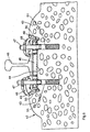
- FIG. 5 shows a detailed view of a plate 42 with a rail support.
- the rail support consists of two humps 43 and a support 44.
- a rail 45 is secured between the two humps 43.
- the rail 45 is thereby arranged with the aid of intermediate layers, which on the one hand cause the height compensation and on the other hand, an attenuation of the rail 45 on the support 44.
- the attachment of the rail 45 by means of screws 47 which are anchored in the concrete of the plate 42 by means of dowels 51 and by means of brackets 49 which are supported on the bump 43 and an angled guide plate 49 and the rail 45.
- the angle guide plates 49 between the bump 43 and the foot of the rail 45 are arranged.
- the rail 45 is held in the desired position in the horizontal direction.
- the angled guide plates 49 may be standard parts which are substantially equal to each other. As a result, an exchange or any use of the angle guide plates 49 during the laying of a rail 45 is possible.
- the plates 42 are first produced by default and only individualized by the machining. As a result, a very fast and thus cost-effective production of a plurality of plates 42 with a single mold is possible. A significantly faster production and installation of prefabricated panels 42 in comparison with earlier manufacturing and assembly methods makes the use of these systems as fixed tracks even more advantageous.
- the present invention is not limited to the illustrated embodiments.
- the principle of the pallet can also be used for other components than for slabs of a solid roadway.
- Conceivable for example, supports or carriers, which can also be produced in circulation production.
Landscapes
- Engineering & Computer Science (AREA)
- Chemical & Material Sciences (AREA)
- Ceramic Engineering (AREA)
- Mechanical Engineering (AREA)
- Structural Engineering (AREA)
- Manufacturing & Machinery (AREA)
- Architecture (AREA)
- Civil Engineering (AREA)
- Manufacturing Of Tubular Articles Or Embedded Moulded Articles (AREA)
- Devices For Post-Treatments, Processing, Supply, Discharge, And Other Processes (AREA)
Claims (46)
- Procédé pour la fabrication d'une pièce précise préfabriquée en béton, le pièce préfabriquée en béton est d'abord réalisée dans un coffrage sur une palette, comme ébauche avec des aciers de précontrainte pour le renforcement,
les aciers de précontrainte de la pièce préfabriquée en béton sont mis en commun en plusieurs sections
les sections, individuellement, sont mises sous contrainte et/ou hors contrainte, qu'il est fabriqué de cette manière une ébauche standardisée
la ébauche standardisée est usinée au moins en ses points fonctionnellement pertinents à une cote individuelle prédéterminée chacun section est mis sous contrainte par un propre dispositif de précontrainte
les aciers de précontrainte d'une section sont simultané mises sous contrainte par un dispositif de précontrainte pour chaque section. - Procédé selon la revendication de brevet 1, caractérisé en ce que l'ébauche, après sa fabrication et avant son usinage, durcit au cours d'un stockage de plusieurs jours.
- Procédé selon l'une quelconque ou plusieurs des revendications de brevet précédentes, caractérisé en ce que les surfaces de montage, comme points fonctionnellement pertinents, sont usinées pour le montage des rails (45) ou comme points de liaison d'une liaison de plusieurs pièces préfabriquées en béton.
- Procédé selon l'une quelconque ou plusieurs des revendications de brevet précédentes, caractérisé en ce que les points usinés sont contrôlés pour ce qui est de leur cote réelle.
- Procédé selon l'une quelconque ou plusieurs des revendications de brevet précédentes, caractérisé en ce que l'usure actuelle de l'outil est prise en compte lors de l'usinage des points fonctionnellement pertinents.
- Procédé selon l'une quelconque ou plusieurs des revendications de brevet précédentes, caractérisé en ce que l'ébauche et/ou une couche appliquée à l'ébauche est usinée notamment par un outil d'usinage.
- Procédé selon l'une quelconque ou plusieurs des revendications de brevet précédentes, caractérisé en ce que l'ébauche comporte des points d'appui de rails, qui, selon les exigences spécifiques à la pièce préfabriquée en béton, sont usinés à la cote nécessaire prédéterminée pour l'itinéraire ultérieur.
- Procédé selon l'une quelconque ou plusieurs des revendications de brevet précédentes, caractérisé en ce que des dispositifs de fixation sont disposés sur l'ébauche, qui sont usinés.
- Procédé selon l'une quelconque ou plusieurs des revendications de brevet précédentes, caractérisé en ce que l'ébauche est réalisée dans un procédé d'usinage épicycloïdal.
- Procédé selon l'une quelconque ou plusieurs des revendications de brevet précédentes, caractérisé en ce que l'ébauche et son coffrage (23, 24) et/ou un dispositif de serrage (30), pendant sa fabrication, est transporté sur une palette mobile.
- Procédé selon l'une quelconque ou plusieurs des revendications de brevet précédentes, caractérisé en ce que diverses stations d'usinage sont prévues, notamment une station de nettoyage, une station de montage de chevilles et de broches, une station de renforçage, une station de serrage, une station de bétonnage avec ou sans station de compactage, une chambre de séchage, une station de détente et de décoffrage et/ou station d'enlèvement de l'ébauche.
- Procédé selon l'une quelconque ou plusieurs des revendications de brevet précédentes, caractérisé en ce que certains au moins desdites stations sont commandées à l'aide de robots.
- Procédé selon l'une quelconque ou plusieurs des revendications de brevet précédentes, caractérisé en ce que des tampons sont prévus entre deux stations.
- Procédé selon l'une quelconque ou plusieurs des revendications de brevet précédentes, caractérisé en ce qu'une armature disposée dans l'ébauche est mise sous précontrainte.
- Procédé selon l'une quelconque ou plusieurs des revendications de brevet précédentes, caractérisé en ce que l'ébauche est réalisée en béton de ciment et de fibres.
- Procédé selon l'une quelconque ou plusieurs des revendications de brevet précédentes, caractérisé en ce que l'armature est disposée dans le sens longitudinal et/ou transversale de l'ébauche.
- Procédé, selon l'une quelconque ou plusieurs des revendications de brevet précédentes, caractérisé en ce que les aciers de précontrainte (35) sont mis sous contrainte indépendamment de la surface de coffrage.
- Procédé selon l'une quelconque ou plusieurs des revendications de brevet précédentes, caractérisé en ce que les aciers de précontrainte (35) sont mis sous contrainte sur le coffrage (23, 24).
- Procédé selon l'une quelconque ou plusieurs des revendications de brevet précédentes, caractérisé en ce que plusieurs aciers de précontraintes (35) sont mis sous contrainte simultanément.
- Procédé selon l'une quelconque ou plusieurs des revendications de brevet précédentes, caractérisé en ce que plusieurs aciers de précontrainte (35) sont reliés par un dispositif d'équilibrage de course et/ou de force.
- Procédé selon l'une quelconque ou plusieurs des revendications de brevet précédentes, caractérisé en ce que pour le décoffrage, le coffrage latéral (24) est démonté en premier lieu de l'ébauche, puis le coffrage de fond (23).
- Procédé selon l'une quelconque ou plusieurs des revendications de brevet précédentes, caractérisé en ce que l'ébauche est séparée du coffrage de fond (23) notamment au moyen de poinçons.
- Procédé selon l'une quelconque ou plusieurs des revendications de brevet précédentes, caractérisé en ce que l'ébauche est d'abord détachée du coffrage de fond (23) et qu'ensuite, on relâche la contrainte des aciers de précontrainte (35).
- Procédé selon l'une quelconque ou plusieurs des revendications de brevet précédentes 1 à 22, caractérisé en ce que l'ébauche est détachée du coffrage de fond (23) en même temps que se relâche la contrainte des aciers de précontrainte (35).
- Procédé selon l'une quelconque ou plusieurs des revendications de brevet précédentes 1 à 22, caractérisé en ce que la contrainte des aciers de précontrainte (35) est relâchée dans un premier temps et que l'ébauche est ensuite détachée du coffrage de fond (23).
- Procédé selon l'une quelconque ou plusieurs des revendications de brevet précédentes, caractérisé en ce que les aciers de précontrainte (35) en surplomb après le décoffrage sont tronçonnés et que l'ébauche est transportée notamment dans un entrepôt de durcissement à l'aide d'un chariot d'enlèvement.
- Procédé selon l'une quelconque ou plusieurs des revendications de brevet précédentes, caractérisé en ce que l'ébauche est transportée notamment après le durcissement dans une zone de post-traitement à l'aide d'un chariot d'enlèvement.
- Procédé selon l'une quelconque ou plusieurs des revendications de brevet précédentes, caractérisé en ce que dans la zone de post-traitement, une matière est appliquée à l'ébauche ou enlevée de l'ébauche, d'une couche appliquée ou d'une pièce rapportée.
- Procédé selon l'une quelconque ou plusieurs des revendications de brevet précédentes, caractérisé en ce que l'usinage de l'ébauche s'effectue sur une machine d'usinage, notamment une machine à fraiser le béton ou une machine à rectifier.
- Procédé selon l'une quelconque ou plusieurs des revendications de brevet précédentes, caractérisé en ce que l'ébauche, pour son usinage, est logée de manière définie selon notamment sa position de montage future.
- Procédé selon l'une quelconque ou plusieurs des revendications de brevet précédentes, caractérisé en ce que l'ébauche est usinée aux futures surfaces d'appui du rail (45) ou à la fixation du rail et/ou aux points de centrage.
- Procédé selon l'une quelconque ou plusieurs des revendications de brevet précédentes, caractérisé en ce que des rails (45) ou des fixations de rails sont installés après l'usinage sur la voie de roulement.
- Palette pour la fabrication d'une pièce préfabriquée en béton mise sous précontrainte,
un coffrage est disposé sur la palette,
plusieurs dispositifs de précontrainte pour aciers de précontrainte sont en outre disposé à la palette pour l'armature de la pièce préfabriquée en béton,
les dispositifs de précontrainte sont logé à la palette indépendamment du coffrage,
chaque dispositif de précontrainte forme une sections individuelle pour la mise sous contrainte par plusieurs aciers de précontrainte mesurage par section
et les aciers de précontrainte d'une section sont simultané mise sous précontrainte dans une dispositif de précontrainte. - Palette selon la revendication de brevet précédente, caractérisée en ce que chaque dispositif de précontrainte (30) comporte au moins un appui de pression et au moins un dispositif de traction.
- Palette selon l'une quelconque ou plusieurs des revendications de brevet précédentes 33 à 34, caractérisée en ce que le dispositif de traction est logé de manière rotative autour de l'appui de pression.
- Palette selon l'une quelconque ou plusieurs des revendications de brevet précédentes 33 à 35, caractérisée en ce que l'une des extrémités du dispositif de traction comporte moins une barre de traction et que l'autre extrémité comporte au moins un dispositif de fixation pour les aciers de précontrainte (35).
- Palette selon l'une quelconque ou plusieurs des revendications de brevet précédentes 33 à 36, caractérisée en ce que le dispositif de fixation est serré et verrouillé au moyen d'une ou plusieurs unités de serrage, notamment un dispositif hydraulique.
- Palette selon l'une quelconque ou plusieurs des revendications de brevet précédentes 33 à 37, caractérisée en ce que le dispositif de fixation est un peigne (36) ou une étampe universelle pour la fixation de plusieurs aciers de précontrainte (35).
- Palette selon l'une quelconque ou plusieurs des revendications de brevet précédentes 33 à 38, caractérisée en ce que le coffrage latéral (24) comporte un schéma correspondant au dispositif de fixation ou à la position des aciers de précontrainte (35).
- Palette selon l'une quelconque ou plusieurs des revendications de brevet précédentes 33 à 39, caractérisée en ce que le dispositif de fixation est installé de manière rotative au dispositif de traction.
- Palette selon l'une quelconque ou plusieurs des revendications de brevet précédentes 33 à 40, caractérisée en ce que les aciers de précontrainte (35), à leurs extrémités, comportent une variation de leur section, qu'ils sont notamment refoulés, qu'ils comportent un dispositif de blocage ou un filetage avec un écrou afin qu'ils puissent être accrochés au dispositif de fixation.
- Palette selon l'une quelconque ou plusieurs des revendications de brevet précédentes 33 à 41, caractérisée en ce que le dispositif de blocage ou le filetage avec l'écrou est utilisé pour saisir, bloquer, serrer et/ou verrouiller les aciers de précontrainte (35) sur le dispositif de fixation.
- Palette selon l'une quelconque ou plusieurs des revendications de brevet précédentes 33 à 42, caractérisée en ce que le coffrage (23, 24) peut être équipé d'inserts divers.
- Palette selon l'une quelconque ou plusieurs des revendications de brevet précédentes 33 à 43, caractérisée en ce que les inserts subdivisent le coffrage (23, 24) en plusieurs pièces de construction.
- Palette selon l'une quelconque ou plusieurs des revendications de brevet précédentes 33 à 44, caractérisée en ce que le coffrage latéral (24) peut être détaché du coffrage de fond (23).
- Palette selon l'une quelconque ou plusieurs des revendications de brevet précédentes 33 à 45, caractérisée en ce que des rails ou des galets sont disposés à la palette (20).
Applications Claiming Priority (5)
| Application Number | Priority Date | Filing Date | Title |
|---|---|---|---|
| DE10107119 | 2001-02-14 | ||
| DE10107119 | 2001-02-14 | ||
| DE10133607A DE10133607C5 (de) | 2001-02-14 | 2001-07-13 | Verfahren und Palette zur Herstellung eines präzisen Betonfertigteiles |
| DE10133607 | 2001-07-13 | ||
| PCT/EP2002/000083 WO2002065022A1 (fr) | 2001-02-14 | 2002-01-08 | Procede et palette pour produire une piece prefabriquee en beton precise |
Publications (3)
| Publication Number | Publication Date |
|---|---|
| EP1360397A1 EP1360397A1 (fr) | 2003-11-12 |
| EP1360397B1 EP1360397B1 (fr) | 2004-07-28 |
| EP1360397B2 true EP1360397B2 (fr) | 2009-11-11 |
Family
ID=26008510
Family Applications (1)
| Application Number | Title | Priority Date | Filing Date |
|---|---|---|---|
| EP02706697A Expired - Lifetime EP1360397B2 (fr) | 2001-02-14 | 2002-01-08 | Procede et palette pour produire une piece prefabriquee en beton precise |
Country Status (4)
| Country | Link |
|---|---|
| EP (1) | EP1360397B2 (fr) |
| AT (1) | ATE272164T1 (fr) |
| AU (1) | AU2002240897A1 (fr) |
| WO (1) | WO2002065022A1 (fr) |
Cited By (1)
| Publication number | Priority date | Publication date | Assignee | Title |
|---|---|---|---|---|
| CN104960089A (zh) * | 2015-07-06 | 2015-10-07 | 天津银龙预应力材料股份有限公司 | 一种高速铁路无砟轨道用双向先张轨道板的生产线 |
Families Citing this family (3)
| Publication number | Priority date | Publication date | Assignee | Title |
|---|---|---|---|---|
| CN101758557B (zh) * | 2009-12-30 | 2012-07-18 | 中铁二十三局集团有限公司 | 轨道板生产方法 |
| DE102010039796A1 (de) * | 2010-06-14 | 2011-12-15 | Max Bögl Bauunternehmung GmbH & Co. KG | Turm mit einem Adapterstück sowie Verfahren zur Herstellung eines Turms mit einem Adapterstück |
| CN102357929A (zh) * | 2011-10-21 | 2012-02-22 | 中铁十二局集团有限公司 | 轨道板预应力张拉系统 |
Citations (6)
| Publication number | Priority date | Publication date | Assignee | Title |
|---|---|---|---|---|
| US4758393A (en) † | 1982-01-21 | 1988-07-19 | Societe Anonyme De Traverses En Beton Arme Systeme Vagneux | Process for casting elements in reinforced concrete |
| DE3931201C1 (en) † | 1989-09-19 | 1990-11-22 | Wayss & Freytag Ag, 6000 Frankfurt, De | Concrete railway sleepers mfr. - uses moving frame mechanism which releases each sleeper immediately |
| EP0436859A2 (fr) † | 1990-01-12 | 1991-07-17 | Wayss & Freytag Aktiengesellschaft | Coffrage pour la fabrication de traverses en béton précontraint avec ancrage immédiat |
| DE4100191C1 (en) † | 1991-01-05 | 1992-05-14 | Stewing Stahl- Und Anlagenbau Gmbh & Co. Kg, 4270 Dorsten, De | Mould for reinforced concrete sleepers - has several mould cavities and has jacking devices for tensioning reinforcement bars |
| EP0592695A1 (fr) † | 1992-10-08 | 1994-04-20 | Wayss & Freytag Aktiengesellschaft | Coffrage pour éléments moulés en béton précontraint |
| DE4203895C2 (de) † | 1992-02-11 | 1996-08-29 | Dyckerhoff & Widmann Ag | Einrichtung zum Herstellen von Fertigbauteilen aus Spannbeton mit sofortigem Verbund, insbesondere von Spannbetonschwellen |
Family Cites Families (6)
| Publication number | Priority date | Publication date | Assignee | Title |
|---|---|---|---|---|
| IT1206781B (it) * | 1987-04-29 | 1989-05-03 | Scac Spa | Impianto per la fabbricazione di manufatti lineari in cemento armato precompresso. |
| FR2714689B1 (fr) * | 1993-12-30 | 1996-03-15 | Rector Sa | Dispositif de crantage de surfaces extérieures de produits en béton. |
| DE19708734C2 (de) * | 1997-03-04 | 2001-05-31 | Dorstener Maschf Ag | Verfahren und Vorrichtung zum Herstellen von plattenförmigen oder balkenförmigen Stahlbetonteilen, insbesondere von Stahlbetonschwellen |
| DE19709535A1 (de) * | 1997-03-10 | 1998-09-17 | Hochtief Ag Hoch Tiefbauten | Verfahren und Vorrichtung zum Betonieren von Schienenstützpunkten für Feste Fahrbahn |
| DE19733909B4 (de) | 1997-08-05 | 2006-07-06 | Max Bögl Bauunternehmung GmbH & Co. KG | Vorgefertigte Stahlbetonfertigteilplatte sowie Verfahren zu deren Herstellung |
| DE19753705A1 (de) * | 1997-12-02 | 1999-06-10 | Teerbau Gmbh Strassenbau | Verfahren, Vorrichtung und Schalungselement zur Herstellung von Nuten in einer Betonplatte sowie schotterloser Oberbau für ein Gleis |
-
2002
- 2002-01-08 AU AU2002240897A patent/AU2002240897A1/en not_active Abandoned
- 2002-01-08 EP EP02706697A patent/EP1360397B2/fr not_active Expired - Lifetime
- 2002-01-08 WO PCT/EP2002/000083 patent/WO2002065022A1/fr not_active Ceased
- 2002-01-08 AT AT02706697T patent/ATE272164T1/de active
Patent Citations (6)
| Publication number | Priority date | Publication date | Assignee | Title |
|---|---|---|---|---|
| US4758393A (en) † | 1982-01-21 | 1988-07-19 | Societe Anonyme De Traverses En Beton Arme Systeme Vagneux | Process for casting elements in reinforced concrete |
| DE3931201C1 (en) † | 1989-09-19 | 1990-11-22 | Wayss & Freytag Ag, 6000 Frankfurt, De | Concrete railway sleepers mfr. - uses moving frame mechanism which releases each sleeper immediately |
| EP0436859A2 (fr) † | 1990-01-12 | 1991-07-17 | Wayss & Freytag Aktiengesellschaft | Coffrage pour la fabrication de traverses en béton précontraint avec ancrage immédiat |
| DE4100191C1 (en) † | 1991-01-05 | 1992-05-14 | Stewing Stahl- Und Anlagenbau Gmbh & Co. Kg, 4270 Dorsten, De | Mould for reinforced concrete sleepers - has several mould cavities and has jacking devices for tensioning reinforcement bars |
| DE4203895C2 (de) † | 1992-02-11 | 1996-08-29 | Dyckerhoff & Widmann Ag | Einrichtung zum Herstellen von Fertigbauteilen aus Spannbeton mit sofortigem Verbund, insbesondere von Spannbetonschwellen |
| EP0592695A1 (fr) † | 1992-10-08 | 1994-04-20 | Wayss & Freytag Aktiengesellschaft | Coffrage pour éléments moulés en béton précontraint |
Cited By (1)
| Publication number | Priority date | Publication date | Assignee | Title |
|---|---|---|---|---|
| CN104960089A (zh) * | 2015-07-06 | 2015-10-07 | 天津银龙预应力材料股份有限公司 | 一种高速铁路无砟轨道用双向先张轨道板的生产线 |
Also Published As
| Publication number | Publication date |
|---|---|
| WO2002065022A1 (fr) | 2002-08-22 |
| WO2002065022A9 (fr) | 2002-12-12 |
| AU2002240897A1 (en) | 2002-08-28 |
| EP1360397A1 (fr) | 2003-11-12 |
| WO2002065022B1 (fr) | 2003-03-20 |
| EP1360397B1 (fr) | 2004-07-28 |
| ATE272164T1 (de) | 2004-08-15 |
Similar Documents
| Publication | Publication Date | Title |
|---|---|---|
| EP1039033B1 (fr) | Méthode de réalisation d'une voie ferrée | |
| DE10133607C5 (de) | Verfahren und Palette zur Herstellung eines präzisen Betonfertigteiles | |
| DE3825508C1 (de) | Verfahren zur Justierung und Befestigung von Funktionsflächen eines Fahrwegs einer elektromagnetischen Schnellbahn und Vorrichtung zur Durchführung des Verfahrens | |
| EP2416933B1 (fr) | Coffrage pour une pièce en béton de précision formant une traverse de chemin de fer | |
| EP1882777B1 (fr) | Procédé pour fabriquer une voie ferrée sans ballast | |
| DE4442498A1 (de) | Fahrbare Betoniermaschine | |
| EP1360397B2 (fr) | Procede et palette pour produire une piece prefabriquee en beton precise | |
| DE102017125152B4 (de) | Verfahren zur Herstellung von Spannbetonschwellen oder Spannbetonweichenschienen | |
| EP0579809B1 (fr) | Procede et dispositif de fabrication d'elements prefabriques en beton precontraint a tension immediate, notamment de traverses en beton precontraint | |
| DE19516163C1 (de) | Verfahren zur positionsgenauen Herstellung oder Einrichtung von Schienenstützpunkten und Maschinensystem für die Durchführung des Verfahrens | |
| EP3486053A1 (fr) | Procédé et installation de fabrication d'éléments creux en béton | |
| EP0715022B1 (fr) | Procédé pour la réalisation ou l'installation de points d'appui de rails en position exacte et système de machines pour l'exécution du procédé | |
| DE10004626A1 (de) | Verfahren zur Herstellung einer Entgleisungsschutzanordnung bei einer Schienenfahrbahn, eine Entgleisungsschutzanordnung umfassende Schienenfahrbahn und Entgleisungsschutzanordnung | |
| EP3424662B1 (fr) | Procédé de fabrication de pièces préfabriquées en béton précontraint | |
| EP1605101A1 (fr) | Procédé et dispositif pour la fabrication d'un panneau multicouche en béton | |
| EP4244424A1 (fr) | Support de voie destiné à un train à sustentation magnétique | |
| EP2010713B1 (fr) | Voie de circulation et procede pour la fabrication de plaques prefabriquees en beton | |
| DE10246898A1 (de) | Vorrichtung zum Justieren der Schwellen von festen Fahrbahnen | |
| DE19627672C2 (de) | Verfahren zur Herstellung einer mit Schienenauflagerelementen aus Beton versehenen Betonfahrbahnplatte einer Schnellfahrbahnstrecke und Verbundankersetzmaschine zur Durchführung des Verfahrens | |
| AT410296B (de) | Verfahren zur herstellung einer tragplatte sowie tragplatte | |
| AT413551B (de) | Verfahren zum herstellen einer festen fahrbahn für schienenfahrzeuge | |
| EP3730263B1 (fr) | Procédé de fabrication d'une pluralité d'éléments coulée de béton en béton précontraint | |
| EP1533420A2 (fr) | Méthode pour construire une voie ferrée sans ballast | |
| DE10138623A1 (de) | Verfahren, Konsolrahmen und Schalung zur Herstellung eines Trägers | |
| DE19916884C2 (de) | Vorrichtung zur Herstellung von Spannbetonteilen |
Legal Events
| Date | Code | Title | Description |
|---|---|---|---|
| PUAI | Public reference made under article 153(3) epc to a published international application that has entered the european phase |
Free format text: ORIGINAL CODE: 0009012 |
|
| 17P | Request for examination filed |
Effective date: 20030727 |
|
| AK | Designated contracting states |
Kind code of ref document: A1 Designated state(s): AT BE CH CY DE DK ES FI FR GB GR IE IT LI LU MC NL PT SE TR |
|
| AX | Request for extension of the european patent |
Extension state: AL LT LV MK RO SI |
|
| GRAP | Despatch of communication of intention to grant a patent |
Free format text: ORIGINAL CODE: EPIDOSNIGR1 |
|
| GRAS | Grant fee paid |
Free format text: ORIGINAL CODE: EPIDOSNIGR3 |
|
| GRAA | (expected) grant |
Free format text: ORIGINAL CODE: 0009210 |
|
| REG | Reference to a national code |
Ref country code: HK Ref legal event code: DE Ref document number: 1059813 Country of ref document: HK |
|
| AK | Designated contracting states |
Kind code of ref document: B1 Designated state(s): AT BE CH CY DE DK ES FI FR GB GR IE IT LI LU MC NL PT SE TR |
|
| PG25 | Lapsed in a contracting state [announced via postgrant information from national office to epo] |
Ref country code: IE Free format text: LAPSE BECAUSE OF FAILURE TO SUBMIT A TRANSLATION OF THE DESCRIPTION OR TO PAY THE FEE WITHIN THE PRESCRIBED TIME-LIMIT Effective date: 20040728 Ref country code: GB Free format text: LAPSE BECAUSE OF FAILURE TO SUBMIT A TRANSLATION OF THE DESCRIPTION OR TO PAY THE FEE WITHIN THE PRESCRIBED TIME-LIMIT Effective date: 20040728 Ref country code: TR Free format text: LAPSE BECAUSE OF FAILURE TO SUBMIT A TRANSLATION OF THE DESCRIPTION OR TO PAY THE FEE WITHIN THE PRESCRIBED TIME-LIMIT Effective date: 20040728 Ref country code: FR Free format text: LAPSE BECAUSE OF FAILURE TO SUBMIT A TRANSLATION OF THE DESCRIPTION OR TO PAY THE FEE WITHIN THE PRESCRIBED TIME-LIMIT Effective date: 20040728 Ref country code: FI Free format text: LAPSE BECAUSE OF FAILURE TO SUBMIT A TRANSLATION OF THE DESCRIPTION OR TO PAY THE FEE WITHIN THE PRESCRIBED TIME-LIMIT Effective date: 20040728 |
|
| REG | Reference to a national code |
Ref country code: GB Ref legal event code: FG4D Free format text: NOT ENGLISH |
|
| REG | Reference to a national code |
Ref country code: CH Ref legal event code: EP |
|
| REG | Reference to a national code |
Ref country code: IE Ref legal event code: FG4D Free format text: GERMAN |
|
| REF | Corresponds to: |
Ref document number: 50200700 Country of ref document: DE Date of ref document: 20040902 Kind code of ref document: P |
|
| PG25 | Lapsed in a contracting state [announced via postgrant information from national office to epo] |
Ref country code: DK Free format text: LAPSE BECAUSE OF FAILURE TO SUBMIT A TRANSLATION OF THE DESCRIPTION OR TO PAY THE FEE WITHIN THE PRESCRIBED TIME-LIMIT Effective date: 20041028 Ref country code: GR Free format text: LAPSE BECAUSE OF FAILURE TO SUBMIT A TRANSLATION OF THE DESCRIPTION OR TO PAY THE FEE WITHIN THE PRESCRIBED TIME-LIMIT Effective date: 20041028 Ref country code: SE Free format text: LAPSE BECAUSE OF FAILURE TO SUBMIT A TRANSLATION OF THE DESCRIPTION OR TO PAY THE FEE WITHIN THE PRESCRIBED TIME-LIMIT Effective date: 20041028 |
|
| PG25 | Lapsed in a contracting state [announced via postgrant information from national office to epo] |
Ref country code: ES Free format text: LAPSE BECAUSE OF FAILURE TO SUBMIT A TRANSLATION OF THE DESCRIPTION OR TO PAY THE FEE WITHIN THE PRESCRIBED TIME-LIMIT Effective date: 20041108 |
|
| PG25 | Lapsed in a contracting state [announced via postgrant information from national office to epo] |
Ref country code: CY Free format text: LAPSE BECAUSE OF FAILURE TO SUBMIT A TRANSLATION OF THE DESCRIPTION OR TO PAY THE FEE WITHIN THE PRESCRIBED TIME-LIMIT Effective date: 20050108 |
|
| LTIE | Lt: invalidation of european patent or patent extension |
Effective date: 20040728 |
|
| GBV | Gb: ep patent (uk) treated as always having been void in accordance with gb section 77(7)/1977 [no translation filed] |
Effective date: 20040728 |
|
| PG25 | Lapsed in a contracting state [announced via postgrant information from national office to epo] |
Ref country code: BE Free format text: LAPSE BECAUSE OF NON-PAYMENT OF DUE FEES Effective date: 20050131 Ref country code: LU Free format text: LAPSE BECAUSE OF NON-PAYMENT OF DUE FEES Effective date: 20050131 Ref country code: MC Free format text: LAPSE BECAUSE OF NON-PAYMENT OF DUE FEES Effective date: 20050131 |
|
| REG | Reference to a national code |
Ref country code: IE Ref legal event code: FD4D |
|
| PLAQ | Examination of admissibility of opposition: information related to despatch of communication + time limit deleted |
Free format text: ORIGINAL CODE: EPIDOSDOPE2 |
|
| PLAR | Examination of admissibility of opposition: information related to receipt of reply deleted |
Free format text: ORIGINAL CODE: EPIDOSDOPE4 |
|
| PLBQ | Unpublished change to opponent data |
Free format text: ORIGINAL CODE: EPIDOS OPPO |
|
| PLBI | Opposition filed |
Free format text: ORIGINAL CODE: 0009260 |
|
| PLAB | Opposition data, opponent's data or that of the opponent's representative modified |
Free format text: ORIGINAL CODE: 0009299OPPO |
|
| PLAQ | Examination of admissibility of opposition: information related to despatch of communication + time limit deleted |
Free format text: ORIGINAL CODE: EPIDOSDOPE2 |
|
| PLAR | Examination of admissibility of opposition: information related to receipt of reply deleted |
Free format text: ORIGINAL CODE: EPIDOSDOPE4 |
|
| PLAX | Notice of opposition and request to file observation + time limit sent |
Free format text: ORIGINAL CODE: EPIDOSNOBS2 |
|
| PLBQ | Unpublished change to opponent data |
Free format text: ORIGINAL CODE: EPIDOS OPPO |
|
| 26 | Opposition filed |
Opponent name: PFLEIDERER INFRASTRUKTURTECHNIK GMBH & CO. KG Effective date: 20050428 |
|
| EN | Fr: translation not filed | ||
| R26 | Opposition filed (corrected) |
Opponent name: PFLEIDERER INFRASTRUKTURTECHNIK GMBH & CO. KG Effective date: 20050428 |
|
| BERE | Be: lapsed |
Owner name: MAX *BOGL BAUUNTERNEHMUNG G.M.B.H. & CO. K.G. Effective date: 20050131 |
|
| NLR1 | Nl: opposition has been filed with the epo |
Opponent name: PFLEIDERER INFRASTRUKTURTECHNIK GMBH & CO. KG |
|
| NLR1 | Nl: opposition has been filed with the epo |
Opponent name: PFLEIDERER INFRASTRUKTURTECHNIK GMBH & CO. KG |
|
| PLAF | Information modified related to communication of a notice of opposition and request to file observations + time limit |
Free format text: ORIGINAL CODE: EPIDOSCOBS2 |
|
| PLBB | Reply of patent proprietor to notice(s) of opposition received |
Free format text: ORIGINAL CODE: EPIDOSNOBS3 |
|
| BERE | Be: lapsed |
Owner name: MAX *BOGL BAUUNTERNEHMUNG G.M.B.H. & CO. K.G. Effective date: 20050131 |
|
| PG25 | Lapsed in a contracting state [announced via postgrant information from national office to epo] |
Ref country code: PT Free format text: LAPSE BECAUSE OF NON-PAYMENT OF DUE FEES Effective date: 20041228 |
|
| PUAH | Patent maintained in amended form |
Free format text: ORIGINAL CODE: 0009272 |
|
| STAA | Information on the status of an ep patent application or granted ep patent |
Free format text: STATUS: PATENT MAINTAINED AS AMENDED |
|
| 27A | Patent maintained in amended form |
Effective date: 20091111 |
|
| AK | Designated contracting states |
Kind code of ref document: B2 Designated state(s): AT BE CH CY DE DK ES FI FR GB GR IE IT LI LU MC NL PT SE TR |
|
| REG | Reference to a national code |
Ref country code: CH Ref legal event code: AEN Free format text: AUFRECHTERHALTUNG DES PATENTES IN GEAENDERTER FORM |
|
| REG | Reference to a national code |
Ref country code: ES Ref legal event code: FD2A Effective date: 20050110 |
|
| NLR2 | Nl: decision of opposition |
Effective date: 20091111 |
|
| NLR3 | Nl: receipt of modified translations in the netherlands language after an opposition procedure | ||
| REG | Reference to a national code |
Ref country code: HK Ref legal event code: WD Ref document number: 1059813 Country of ref document: HK |
|
| PGFP | Annual fee paid to national office [announced via postgrant information from national office to epo] |
Ref country code: NL Payment date: 20150122 Year of fee payment: 14 |
|
| PGFP | Annual fee paid to national office [announced via postgrant information from national office to epo] |
Ref country code: IT Payment date: 20150123 Year of fee payment: 14 Ref country code: CH Payment date: 20150122 Year of fee payment: 14 Ref country code: DE Payment date: 20150116 Year of fee payment: 14 |
|
| PGFP | Annual fee paid to national office [announced via postgrant information from national office to epo] |
Ref country code: AT Payment date: 20150122 Year of fee payment: 14 |
|
| REG | Reference to a national code |
Ref country code: DE Ref legal event code: R119 Ref document number: 50200700 Country of ref document: DE |
|
| REG | Reference to a national code |
Ref country code: CH Ref legal event code: PL |
|
| REG | Reference to a national code |
Ref country code: AT Ref legal event code: MM01 Ref document number: 272164 Country of ref document: AT Kind code of ref document: T Effective date: 20160108 |
|
| REG | Reference to a national code |
Ref country code: NL Ref legal event code: MM Effective date: 20160201 |
|
| PG25 | Lapsed in a contracting state [announced via postgrant information from national office to epo] |
Ref country code: DE Free format text: LAPSE BECAUSE OF NON-PAYMENT OF DUE FEES Effective date: 20160802 Ref country code: LI Free format text: LAPSE BECAUSE OF NON-PAYMENT OF DUE FEES Effective date: 20160131 Ref country code: CH Free format text: LAPSE BECAUSE OF NON-PAYMENT OF DUE FEES Effective date: 20160131 |
|
| PG25 | Lapsed in a contracting state [announced via postgrant information from national office to epo] |
Ref country code: NL Free format text: LAPSE BECAUSE OF NON-PAYMENT OF DUE FEES Effective date: 20160201 Ref country code: AT Free format text: LAPSE BECAUSE OF NON-PAYMENT OF DUE FEES Effective date: 20160108 |
|
| PG25 | Lapsed in a contracting state [announced via postgrant information from national office to epo] |
Ref country code: IT Free format text: LAPSE BECAUSE OF NON-PAYMENT OF DUE FEES Effective date: 20160108 |