EP1359253A2 - Korrektureinrichtung zur Korrektur von in Betonschwellen eingebetteten Halterungselementen und Schwellenform - Google Patents
Korrektureinrichtung zur Korrektur von in Betonschwellen eingebetteten Halterungselementen und Schwellenform Download PDFInfo
- Publication number
- EP1359253A2 EP1359253A2 EP03007544A EP03007544A EP1359253A2 EP 1359253 A2 EP1359253 A2 EP 1359253A2 EP 03007544 A EP03007544 A EP 03007544A EP 03007544 A EP03007544 A EP 03007544A EP 1359253 A2 EP1359253 A2 EP 1359253A2
- Authority
- EP
- European Patent Office
- Prior art keywords
- positioning
- concrete
- elements
- receiving opening
- mold
- Prior art date
- Legal status (The legal status is an assumption and is not a legal conclusion. Google has not performed a legal analysis and makes no representation as to the accuracy of the status listed.)
- Granted
Links
- 241001669679 Eleotris Species 0.000 title claims description 40
- 238000000034 method Methods 0.000 claims abstract description 20
- 238000004519 manufacturing process Methods 0.000 claims abstract description 19
- 238000012937 correction Methods 0.000 claims description 42
- 239000000463 material Substances 0.000 claims description 10
- 238000003825 pressing Methods 0.000 claims description 8
- 229910052751 metal Inorganic materials 0.000 claims description 7
- 239000002184 metal Substances 0.000 claims description 7
- 239000013013 elastic material Substances 0.000 claims description 6
- 238000013459 approach Methods 0.000 claims description 5
- 238000003780 insertion Methods 0.000 claims description 4
- 230000037431 insertion Effects 0.000 claims description 4
- 238000006073 displacement reaction Methods 0.000 claims description 3
- 238000004873 anchoring Methods 0.000 description 6
- 239000002002 slurry Substances 0.000 description 4
- 238000009415 formwork Methods 0.000 description 3
- 230000035515 penetration Effects 0.000 description 3
- 230000015572 biosynthetic process Effects 0.000 description 2
- 238000013461 design Methods 0.000 description 2
- 230000006978 adaptation Effects 0.000 description 1
- 238000005056 compaction Methods 0.000 description 1
- 238000011161 development Methods 0.000 description 1
- 230000018109 developmental process Effects 0.000 description 1
- 230000000694 effects Effects 0.000 description 1
- 239000012530 fluid Substances 0.000 description 1
- 239000007788 liquid Substances 0.000 description 1
- 238000013507 mapping Methods 0.000 description 1
- 238000005259 measurement Methods 0.000 description 1
- 230000002093 peripheral effect Effects 0.000 description 1
- 238000012552 review Methods 0.000 description 1
- 238000007789 sealing Methods 0.000 description 1
- 238000007493 shaping process Methods 0.000 description 1
- 238000012549 training Methods 0.000 description 1
- UONOETXJSWQNOL-UHFFFAOYSA-N tungsten carbide Chemical compound [W+]#[C-] UONOETXJSWQNOL-UHFFFAOYSA-N 0.000 description 1
Images


Classifications
-
- E—FIXED CONSTRUCTIONS
- E01—CONSTRUCTION OF ROADS, RAILWAYS, OR BRIDGES
- E01B—PERMANENT WAY; PERMANENT-WAY TOOLS; MACHINES FOR MAKING RAILWAYS OF ALL KINDS
- E01B29/00—Laying, rebuilding, or taking-up tracks; Tools or machines therefor
- E01B29/42—Undetachably joining or fastening track components in or on the track, e.g. by welding, by gluing; Pre-assembling track components by gluing; Sealing joints with filling components
-
- E—FIXED CONSTRUCTIONS
- E01—CONSTRUCTION OF ROADS, RAILWAYS, OR BRIDGES
- E01B—PERMANENT WAY; PERMANENT-WAY TOOLS; MACHINES FOR MAKING RAILWAYS OF ALL KINDS
- E01B29/00—Laying, rebuilding, or taking-up tracks; Tools or machines therefor
- E01B29/32—Installing or removing track components, not covered by the preceding groups, e.g. sole-plates, rail anchors
Definitions
- the invention relates to a correction device for correcting the relative position of support elements for railroad tracks embedded in concrete sleepers in a state of not yet fully hardened concrete.
- each one from a mold bottom and side walls have limited mold cavity.
- There are receiving openings in the mold bottom provided in which rail support elements from Mold cavity are used so that the respective anchoring part of the rail support member lies within the mold cavity and the rail holding part used to fasten the rail outside of the mold cavity.
- the receiving openings Arranged and dimensioned so that the bracket elements already during insertion into the corresponding receiving openings positioned according to the track-related specifications (track width, etc.) become.
- the invention has for its object the manufacture of sleepers of the type mentioned with increased productivity and ensuring the relative positioning requirements for the bracket elements on the Enable thresholds.
- the relative target positions of the individual mounting elements are required not right from the start by someone tight engagement between the receiving openings and the support members be determined, but these can - if necessary - only in Subsequently determined or corrected by means of a correction device which, after the complete removal of the formwork from the not yet hardened Threshold assigned to the threshold, for example placed on the concrete is, preferably in a state of the concrete in which this replenish any cavities that arise as a result of the correction can.
- the mounting elements for relative positioning between a respective positioning element and the positioning section assigned to it can be clamped, after the position correction, the support elements, for example long defined to hold on until, for example, as a result of the correction cavities in the concrete have been replenished or the Concrete has reached a degree of hardening in which a further position fixation of the respective mounting elements is no longer necessary.
- At least one mechanical, electrical, pneumatic or hydraulic drive for adjustment at least one of the positioning elements is provided.
- At least one concrete pressing and / or pressing arrangement is provided.
- the concrete pressure and / or pressure arrangement is designed for this is, pushing forces acting in the longitudinal direction of the threshold on the still deformable concrete to exercise the threshold. This in the longitudinal direction of the threshold acting pushing forces can be particularly useful as a result be achieved that at least one threshold side on the movable Positioning element provided projection for engagement in the still plastically deformable concrete is provided.
- At least one impact or vibration device can be provided be the support elements during the correction or / and the concrete at least in the area of the mounting elements in light Vibrations are offset or shaken in order to create from the outset counteracting crevices or cavities or resulting crevices or at least partially close cavities again.
- the blow or / and Vibration device can have a striking arrangement at least one preferably magnetically operated impact weight exhibit.
- the distance between the target distance of the bracket elements defines, and / or that the positioning gauge at least two positioning sections has, the distance in the longitudinal direction of the threshold corresponding direction a target distance between at least two support elements that define the track width of a track.
- This enables you to do everything for the respective track system important relative positions or target distances at the same time, however, it should not be excluded that the different target distances the support elements are set one after the other, d. H. that, for example, first the target distance between two mounting elements is set, which determines the track width of a track, and that Only then the set distance of the bracket elements is set is that is essential for holding a rail.
- the correction device for approximation in an approach direction that is essentially orthogonal to the threshold top is formed against the threshold, as a result particularly simple positioning of the correction device with respect to the individual mounting elements is possible.
- the invention further relates to a method for checking and if necessary Correction of the relative position of those embedded in concrete sleepers Support elements for railroad tracks in a condition not yet fully hardened concrete using the invention Correction device, which is characterized by the following steps is: assigning the correction device to an at least partially demolded, not yet fully hardened concrete sleeper, which with partially embedded support elements for railroad tracks is equipped such that a section protruding from the concrete of a respective mounting element between each Positioning element and the respectively assigned positioning section is included, adjusting the positioning elements in Direction to the associated positioning section for manufacture a positioning intervention of the respective mounting element at least with the relevant positioning element and, if so far no positioning intervention of the respective mounting element with the assigned positioning section, moving the respective Bracket element by means of the positioning element in the direction of each assigned positioning section for producing a positioning intervention both with the relevant positioning element as also with the positioning section assigned to it.
- the mapping is the placement of the correction device on the top an at least partially demolded, not yet fully cured Include concrete sleeper.
- bracket elements on the concrete sleeper For a very exact positioning of the bracket elements on the concrete sleeper to ensure and avoid incorrect operation can continue be provided that the mounting elements for relative positioning between a respective positioning element and this assigned positioning section can be clamped.
- the support elements To columns or columns that may arise from the position correction Cavities in the concrete, especially between the concrete and anchoring feet the support elements to counteract, so from the outset the formation of such gaps or cavities as far as possible prevent or close any crevices or cavities that arise, it is expedient that on the mounting elements and / or this surrounding concrete in the course of correcting compressive forces or / and Impact impulses and / or vibrations are exerted.
- the mounting elements embedding Concrete in the course of correcting in the direction of the adjustment movement of the respective positioning element in the direction of the respective mounting element is moved. This enables you to do so in a simple manner at the same time the respective mounting elements in their relative position move as well as the surrounding concrete in the correction direction to add unwanted gaps or cavities between the Anchoring feet of the support elements and the concrete Act.
- the manufacture of concrete sleepers can be advantageous in the so-called “immediate demoulding process", in which in concrete sleepers manufactured directly or relatively in a sleeper shape shortly after pouring in concrete material and, if necessary, compacting the concrete material can be switched off by a vibrator.
- the Bracket elements it is possible to the bracket elements in a known Way via receiving openings provided in the sleeper shape to position to insert the rail support elements, or else the rail mounting elements only after the formwork has been removed Concrete sleeper, for example by means of its own mounting element planting device to press into the still soft concrete of the threshold and then the respective relative positions of the mounting elements to be checked by means of a correction device according to the invention and correct if necessary.
- the mounting elements are adjusted and / or held, such as an angle adjustment around a vertical axis and / or alignment the support elements in the transverse direction and / or a relative altitude of the support elements.
- the mounting elements mentioned above can be conventional rail mounting elements, possibly so-called Pandrol fast clips, act.
- the invention further relates to a Sleeper mold for the production of concrete sleepers for railroad tracks, comprising a mold base with at least one receiving opening for the insertion of a mounting element and at least one contact point in association with the receiving opening at which the mounting element in used state directly or indirectly on the mold base in predetermined position is supported, and the receiving opening in Essentially defining edge area.
- Such a threshold form is for example from WO 01/00929 A1 known. Problems can arise with such threshold forms occur that on the one hand freshly poured concrete slurry into the Area of engagement between the support member and the Mold floor can penetrate and thus the formwork later Threshold is complicated and that on the other hand the investment site of the Mold floor during continuous operation of the device for the production of Concrete sleepers are subject to heavy wear.
- the present invention lies in the second aspect the task underlying a threshold form for the production of To provide concrete sleepers for railroad tracks, which one improved engagement between the support member and the Molded bottom allows.
- the third aspect of the invention proposes to reduce the wear of the contact points on the mold base.
- the mold bottom at its edge area a number of the Receiving opening at least partially circumferential edges from a has elastic material, such that when in the receiving opening insert element the threshold shape in the area of Intake opening against leakage from incomplete hardened concrete from the threshold form between the edge area and Bracket element and / or against the occurrence of not completely hardened concrete in an engagement area between the mold base and the mounting element is substantially sealed.
- the elastic material preferably forms at least one elastic Lip that on the mounting element used in the receiving opening Facility is coming.
- An elastic lip offers the advantages of being one against one Penetration of concrete slurry sealed engagement between the Bracket and the mold bottom is created while on the other hand an easy detachment of the threshold form from the Bracket elements when removing the threshold is guaranteed.
- the latter advantage is particularly important in the immediate demoulding process, where a concrete sleeper immediately after filling and compacting of the concrete is removed, because with this method a force effect the support elements when lifting the sleeper shape from the Concrete threshold must be kept as low as possible in order to Not yet move the bracket elements from their target position to avoid completely hardened concrete as far as possible.
- At least one contact point will be part of the peripheral area or define the receiving opening together with the edge area.
- Threshold form are the at least one receiving opening, the at least one a contact point and possibly the edge or edges part of a interchangeable frame, which is assigned to an opening of the Molded bottom mounted or is mountable.
- An advantage of this Embodiment is e.g. B. that the threshold form in a simple manner Use with different types of mounting brackets can be customized by for a particular type of bracket a specific frame with a correspondingly adapted receiving opening, d. H. appropriately trained contact points and possibly edges, on Molded base can be mounted. It is also considered an advantage of exchangeable framework considered that this in the case of a Continuous operation of the device occurring wear easily against one another frame, for example against a still unworn one Frame that can be replaced.
- Threshold form is the opening or the interchangeable Molded bottom section of a rest of the Detachable threshold form.
- This can advantageously be used for this be used in a demoulding process, in particular a partial or Immediate demoulding process, at least this bottom section of the mold not fully cured threshold left.
- partial or immediate demoulding process is for example in WO 01/00929 A1 and enables partial demoulding not yet fully cured threshold leaving one of the Bracket elements receiving mold bottom section to one hand a quick reuse of the detached part of the threshold form to achieve and on the other hand the necessary stability of the location of the To ensure support elements during the hardening of the concrete.
- the mold base of the sleeper shape can in Area of the receiving opening at least one of the mold bottom associated contact element - be provided, which one opposite forms the mold base to the outside, where the Bracket element in the inserted state directly or indirectly on the Molded base is supported in a predetermined position.
- Such an investment site can in addition to the essentially in the plane of the mold bottom lying contact points can be provided to the mounting element in to stabilize its used condition.
- the contact point of the described investment element from one versus one Mold-forming material made of wear-resistant material and can advantageously be formed from a hard metal plate.
- Fig. 1 shows a concrete sleeper 10, in the for holding not shown Rails of a track Pandrol support elements 12 with one respective bracket element foot 13 are anchored. Over the top 14 the concrete sleeper 10 are each sections of the support elements before, which are also referred to as shoulders 16. The shoulders 16 point a special design on the rails using special, referred to as "clips" springs between two associated with a rail Clamping bracket elements in a manner known per se.
- a threshold form not shown, in a the top 14 of the threshold 10 associated bottom wall receiving openings in which the mounting elements are inserted in such a way that the respective foot 13 protrudes into a mold cavity of the mold and the respective shoulder 16 is arranged on the other side of the bottom wall is.
- WO 01/00929 A1 the disclosure of which is included here. This makes it possible for the foot 13 embedded in the concrete filled in the sleeper mold.
- the production the threshold 10 can advantageously be used in the "immediate demoulding process" in which the concrete sleeper 10 manufactured in the sleeper form immediately after a concrete has been filled and, if necessary, compacted Vibrator is completely switched off, which has the advantage that the threshold forms with this process immediately for the production of further Sleepers can be used.
- bracket elements 12 on the predetermined relative positions must assume the threshold 10 accordingly the respective track system for which the threshold 10 determines is. So, according to a conventional approach, the bracket elements 12 during the shaping and curing of the threshold in its position or on the threshold 10 on the track width of a track and that for Attachment of the rails essential spacing a, b, c in their relative Layers are set and held. In contrast, according to the invention a review and, if necessary, a correction or a mandatory one Correction of these positions after the demoulding is not yet complete cured threshold provided.
- the correction device 18 essentially consists of two position correction gauges 20, which are connected to one another via a supporting beam 22 are connected.
- the combination of the support beam 22 and the two Positioning Gauges 20 themselves can also be used as a "Positioning Gauge" be identified.
- the support beam 22 consists of two in the present embodiment pipe sections which are displaceable relative to one another and can be fixed to one another 24 and 26, which makes the correction device 18 easier Can be adapted to different track gauges.
- the support beam could also be used for a fixed, predetermined track gauge be provided without adjustment.
- the support beam 22nd provided at its outer ends with eyelets 28 to attach it to a crane hang.
- each individual position correction gauge 20 includes one in this centrally arranged distance gauge 30 with two in the longitudinal direction of the threshold spaced positioning sections 32, their spacing the target distance b, c of two associated with each other with respect to a rail Bracket elements 12 defined.
- the position correction doctrine also includes 20 two positioning elements 34, each by means of a for example hydraulic drive 36 relative to distance gauge 30 at least in a direction corresponding to the longitudinal direction of the threshold movable and relative to an associated positioning section 32 of the distance gauge 30 are adjustable.
- the positioning elements 34 and the positioning sections 32 are before a position correction arranged so that one from the concrete of the threshold 10 protruding shoulder 16 of a respective mounting element 12 in a Approach of the correction device 18 in a to the threshold top 14 in a substantially orthogonal approach to the threshold without difficulty between the positioning elements 34 and the assigned positioning section 32 can be accommodated.
- the mounting elements 12 can be connected to this by means of the positioning elements 34 in the direction of the respectively assigned positioning section 32 are moved to shoulder 16 between each Positioning element 34 and the positioning section assigned to it 32 to clamp. You are able to do that of the left Rail-associated mounting elements on the one hand and those on the right On the other hand, rail-associated mounting elements in a simple manner relative to each other in terms of relative positions to correct the distance dimensions mentioned above.
- the distance measure a is in the case of the embodiment with the adjustable support beam for an appropriate adjustment of the relative position of the two To provide pipe sections 24 and 26.
- the positioning elements 34 each provided on the threshold side with a projection 38 which in the still plastically deformable concrete engages the threshold 10 and at the side Moving the positioning elements 34 concrete against the feet 13 the support elements 12 presses. You could also do it think using a suitable feed device to place fresh concrete in the To supply the surrounding area of the support elements in threshold concrete.
- the position correction gauge 20 can be provided with a striking arrangement 40 which essentially consists of an impact weight 42, by means of a magnet 44 along an impact weight guide 46 can be lifted and dropped again, so that when opened on the distance gauge 30, depending on the size of the weight, the Lifting height and lifting frequency, variably adjustable beats or / and vibrations can be generated, which also lead to a dense Place the anchoring feet in the concrete.
- a striking arrangement 40 which essentially consists of an impact weight 42, by means of a magnet 44 along an impact weight guide 46 can be lifted and dropped again, so that when opened on the distance gauge 30, depending on the size of the weight, the Lifting height and lifting frequency, variably adjustable beats or / and vibrations can be generated, which also lead to a dense Place the anchoring feet in the concrete.
- the impact weight guide 46 with the distance gauge 30 welded and in the area of the magnet 44 with a Pipe section 48 connected together with the impact weight guide 46 serves to fasten the distance gauge 30 to the support beam 22.
- Attachment of the positioning elements 34 and the hydraulic drives 36 is used in the longitudinal direction of the threshold and parallel to the support beam 22 extending support 50 to which it is fastened by means of brackets 52 are.
- the carrier 50 in turn is on the support beam 22 by means of the pipe section 48 and two support elements 54 on both sides of the pipe section 48 attached.
- the correction device placed on the top 14 of the newly demolded concrete sleeper 10 so that a shoulder 16 protruding from the concrete of a respective mounting element 12 each between a positioning element 34 and is assigned to the respectively assigned positioning section 32.
- the positioning elements 34 are then moved in the direction of the respective assigned positioning section 32 by means of the hydraulic drives 36 moved until the respective positioning element 34 on the Shoulder 16 of the respective support member 12 abuts.
- Simultaneously with the setting or / and keeping the target distances a, b and c can also further degrees of freedom of the mounting elements set or held such as an angle adjustment about a vertical axis or / and Alignment of the support elements in the transverse direction and / or a relative Height of the bracket elements.
- FIG. 3 shows a Pandrol mounting element 112 for mounting of rails, not shown, with a support element foot 113, which for fastening the support elements 112 in the concrete 110 of the Threshold 111 is embedded.
- the support member 112 also has Shoulders 116 on the attachment of the rails, not shown serve the threshold 111.
- the bracket has approximately vertically middle position four projecting lugs 119a to 119d, which in the inserted state of the holding element 112 with as Tungsten carbide plates executed contact points 121a to 121d one Threshold form, in the present case specifically a frame 131 of the threshold form, come to the plant.
- the Pandrol bracket member 112 is one protruding part 123 formed on a portion 143 of the Frame 131 comes to the plant.
- the frame 131 has a division at the point designated 135 in order to a check in accordance with proposals of WO 01/00929 A1 and correcting the relative position of the embedded support members 112 in the not yet fully hardened concrete 110.
- the division 135 of the frame 131 allows adjustment or the structure of the for compliance with the track gauge or for the Adaptation to a certain track system important dimensions a, b and c 10 of WO 01/00929 A1.
- the receiving opening 133 of the intermediate frame 134 is defined by the contact points 121a to 121d and through the receiving opening 133 partially circumferential and the edge area of the receiving opening 133 forming edges 137.
- edges 137 consist an elastic material and are in the embodiment of FIG. 4 as elastic lips 139 executed.
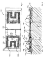
- Fig. 5 shows a sectional view of a frame 131 receiving Mold bottom section 141 of a sleeper shape according to the invention and two schematically indicated mounting elements 112 in the inserted Status.
- the mold base 141 and the frame 131 are in FIG. 5 depicted state in contact with that given in the threshold form Concrete 110 and the bracket feet 113 are in the concrete 110 of the threshold 111 to be produced is embedded. It supports itself in this state that shown for example in Fig. 5 on the left Support element 112 with its protruding lugs 119a to 119d the hard metal plates of the contact points 121a to 121d of Intermediate frame 134.
- the mounting element is also supported 112 in the embodiment shown in FIG.
- FIG. 5 it is illustrated in FIG. 5 how the elastic lips 139 of the Edge area of the receiving opening 133, the holding element 112 circulate and with this at the points designated 147 to one Line system come. This prevents liquid Concrete slurry in the area of engagement between the Bracket element 112 and the intermediate frame 134 can penetrate or can emerge from the threshold shape through this area.
- the threshold form according to the invention and its developments thus an engagement between a mold base section 141 or Frame 131, 134 and a support member 112 ready, which on the one hand a shifting of the mounting element 112 when the Threshold form for the purpose of compacting the concrete inside 110 kept to a minimum, at the same time the penetration more fluid Concrete slip in the area of the intervention largely prevented and on the other hand, detaching the mold bottom section from the Bracket element 112 when demoulding the sleepers in partial or Immediate demoulding process made easier.
- the invention is not based on that shown in FIGS. 4 and 5 Embodiment limited. It would be conceivable, for example, on the To waive investment points 121a to 121d, especially if that Supporting the support members 112 in the inserted state during filling, compacting and curing the concrete 110 from one outer holding device and / or positioning device becomes.
Landscapes
- Engineering & Computer Science (AREA)
- Architecture (AREA)
- Civil Engineering (AREA)
- Structural Engineering (AREA)
- Machines For Laying And Maintaining Railways (AREA)
- Moulds, Cores, Or Mandrels (AREA)
Abstract
Description
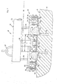
- Fig. 1
- eine schematische Seitenansicht einer Korrektureinrichtung, welche zur Korrektur von Halterungselementen einer Schwelle auf die Schwelle abgesenkt ist,
- Fig. 2
- eine detaillierte Schnittansicht des linken Abschnitts der auf der Betonschwelle abgesetzten Korrektureinrichtung,
- Fig. 3
- eine Vorderansicht und eine Seitenansicht eines Pandrol-Halterungselementes,
- Fig. 4
- eine Draufsicht auf einen zwei Aufnahmeöffnungen enthaltenden Rahmen und
- Fig. 5
- eine Schnittansicht eines einen auswechselbaren Rahmen und zwei Aufnahmeöffnungen aufweisenden Formbodenabschnitt in Kontakt mit einer Betonschwelle sowie zwei schematisch angedeutete Halterungselemente im eingesetzten Zustand.
Claims (30)
- Korrektureinrichtung zur Korrektur der Relativposition von in Betonschwellen (10) eingebetteten Halterungselementen (12) für Eisenbahnschienen in einem Zustand noch nicht vollständig erhärteten Betons, umfassend:dadurch gekennzeichnet, dass wenigstens zwei relativ zur Positionierungslehre (20; 20, 22, 20) zumindest in einer der Schwellen-Längsrichtung entsprechenden Richtung bewegliche Positionierungselemente (34) vorgesehen sind, die relativ zu einem jeweils zugeordneten Positionierungsabschnitt (32) der Positionierungslehre (20; 20, 22, 20) verstellbar sind, wobei die Positionierungselemente (34) und Positionierungsabschnitte (32) derart angeordnet und die Positionierungselemente (34) derart verstellbar sind, dasseine zumindest einen Soll-Abstand zwischen wenigstens zwei Halterungselementen (12) angebende, mit den Halterungselementen (12) in Positionierungseingriff bringbare Positionierungslehre (20; 20, 22, 20),i) zwischen den Positionierungselementen (34) und dem jeweils zugeordneten Positionierungsabschnitt (32) ein aus dem Beton vorstehender Abschnitt (16) eines jeweiligen Halterungselements (12) aufnehmbar ist, undii) die Positionierungselemente (34) in Richtung zum jeweils zugeordneten Positionierungsabschnitt (32) verstellbar sind zur Herstellung eines Positionierungseingriffs des jeweiligen Halterungselements (12) sowohl mit dem betreffenden Positionierungselement (34) als auch mit dem diesem zugeordneten Positionierungsabschnitt (32).
- Einrichtung nach Anspruch 1, dadurch gekennzeichnet, dass die Halterungselemente (12) zur relativen Positionierung zwischen einem jeweiligen Positionierungselement (32) und dem diesem zugeordneten Positionierungsabschnitt (34) einspannbar sind.
- Einrichtung nach Anspruch 1 oder 2, dadurch gekennzeichnet, dass wenigstens ein mechanischer, elektrischer, pneumatischer oder hydraulischer Antrieb (36) zur Verstellung wenigstens eines der Positionierungselemente (34) vorgesehen ist.
- Einrichtung nach einem der vorhergehenden Ansprüche, dadurch gekennzeichnet, dass wenigstens eine Beton-Andrück- oder/und Nachdrückanordnung (38) vorgesehen ist.
- Einrichtung nach Anspruch 4, dadurch gekennzeichnet, dass die Beton-Andrück- oder/und Nachdrückanordnung (38) dafür ausgebildet ist, in Schwellen-Längsrichtung wirkende Schiebekräfte auf den noch plastisch deformierbaren Beton auszuüben.
- Einrichtung nach Anspruch 4 oder 5, dadurch gekennzeichnet, dass die Beton-Andrück-oder/und Nachdrückanordnung wenigstens einen schwellenseitig an dem beweglichen Positionierungselement vorgesehenen Vorsprung (38) zum Eingriff in den noch plastisch deformierbaren Beton aufweist.
- Einrichtung nach einem der vorhergehenden Ansprüche, dadurch gekennzeichnet, dass wenigstens eine Schlag- oder/und Vibrationseinrichtung (40) vorgesehen ist.
- Einrichtung nach Anspruch 7, dadurch gekennzeichnet, dass die Schlag- oder/und Vibrationseinrichtung eine Schlaganordnung (40) mit wenigstens einem vorzugsweise magnetisch betätigbaren Schlaggewicht (42) aufweist.
- Einrichtung nach einem der vorhergehenden Ansprüche, dadurch gekennzeichnet, dass zwei gemeinsam zur Halterung einer Schiene dienenden Halterungselementen (12) wenigstens zwei Positionierungsabschnitte (32) zugeordnet sind, deren Abstand den Soll-Abstand (b, c) der Halterungselemente (12) definiert.
- Einrichtung nach einem der vorhergehenden Ansprüche, dadurch gekennzeichnet, dass die Positionierungslehre wenigstens zwei Positionierungsabschnitte (32) aufweist, deren Abstand (a) in der der Schwellen-Längsrichtung entsprechenden Richtung einen Soll-Abstand (a) zwischen wenigstens zwei Halterungselementen (12) definiert, der die Spurweite (a) eines Gleises festlegt.
- Einrichtung nach einem der vorhergehenden Ansprüche, dadurch gekennzeichnet, dass die Korrektureinrichtung (18) zur Annäherung in einer zur Schwellenoberseite (14) im Wesentlichen orthogonalen Annäherungsrichtung gegen die Schwelle (10) ausgebildet ist.
- Verfahren zur Überprüfung und bedarfsweisen Korrektur der Relativposition von in Betonschwellen (10) eingebetteten Halterungselementen (12) für Eisenbahnschienen in einem Zustand noch nicht vollständig ausgehärteten Betons unter Verwendung der Korrektureinrichtung (10) nach wenigstens einem der Ansprüche 1 bis 11, gekennzeichnet durch die folgenden Schritte:Zuordnen der Korrektureinrichtung zu einer zumindest teilweise entformten, noch nicht vollständig ausgehärteten Betonschwelle (10), welche mit teilweise eingebetteten Halterungselementen (12) für Eisenbahnschienen bestückt ist, derart, dass ein aus dem Beton vorstehender Abschnitt (16) eines jeweiligen Halterungselements (12) jeweils zwischen einem Positionierungselement (34) und dem jeweils zugeordneten Positionierungsabschnitt (32) aufgenommen ist,Verstellen der Positionierungselemente (34) in Richtung zum jeweils zugeordneten Positionierungsabschnitt (32) zur Herstellung eines Positionierungseingriffs des jeweiligen Halterungselements (12) zumindest mit dem betreffenden Positionierungselement (34) und,soweit bisher kein Positionierungseingriff des jeweiligen Halterungselements (12) mit dem zugeordneten Positionierungsabschnitt (32) besteht: Verschieben des jeweiligen Halterungselements (12) mittels des Positionierungselements (34) in Richtung zum jeweils zugeordneten Positionierungsabschnitt (32) zur Herstellung eines Positionierungseingriffs sowohl mit dem betreffenden Positionierungselement (34) als auch mit dem diesem zugeordneten Positionierungsabschnitt (32).
- Verfahren nach Anspruch 12, dadurch gekennzeichnet, dass das Zuordnen das Auflegen der Korrektureinrichtung (18) auf die Oberseite (14) umfasst.
- Verfahren nach Anspruch 12 oder 13, dadurch gekennzeichnet, dass die Halterungselemente (12) zur relativen Positionierung zwischen einem jeweiligen Positionierungselement (34) und dem diesem zugeordneten Positionierungsabschnitt (32) eingespannt werden.
- Verfahren nach einem der Ansprüche 12 bis 14, dadurch gekennzeichnet, dass auf die Halterungselemente (12) oder/und den diese umgebenden Beton im Zuge des Korrigierens Druckkräfte oder/und Schlagimpulse oder/und Vibrationen ausgeübt werden.
- Verfahren nach einem der Ansprüche 12 bis 15, dadurch gekennzeichnet, dass die Halterungselemente einbettender Beton im Zuge des Korrigierens in Richtung der Verstellbewegung des jeweiligen Positionierungselements (34) in Richtung zum jeweiligen Halterungselement (12) verschoben wird.
- Verfahren nach einem der Ansprüche 12 bis 16, dadurch gekennzeichnet, dass die bezüglich einer Schiene einander zugeordneten Halterungselemente (12) hinsichtlich eines für die Schienenbefestigung wesentlichen Abstandsmaßes (b, c) in ihren relativen Lagen korrigiert werden.
- Verfahren nach einem der Ansprüche 12 bis 17, dadurch gekennzeichnet, dass die bezüglich den Schienen eines Gleises einander zugeordneten Halterungselemente hinsichtlich eines für die Spurweite des Gleises wesentlichen relativen Abstandsmaßes (a) in ihren relativen Lagen korrigiert werden.
- Verfahren nach einem der Ansprüche 12 bis 18, dadurch gekennzeichnet, dass gleichzeitig mit dem Einstellen oder/und Halten der Soll-Abstände (a, b, c) wenigstens ein weiterer Positionierungsfreiheitsgrad der Halterungselemente eingestellt oder/und gehalten wird, wie etwa eine Winkeleinstellung um eine Hochachse oder/und Fluchtung der Halterungselemente in Querrichtung oder/und eine relative Höhenlage der Halterungselemente.
- Verfahren nach einem der Ansprüche 12 bis 19, dadurch gekennzeichnet, dass es in Bezug auf herkömmliche Schienen-Halterungselemente, ggf. so genannte Pandrol-Fastclips, angewendet wird.
- Schwellenform zur Herstellung von Betonschwellen (111) für Eisenbahnschienen, umfassend:dadurch gekennzeichnet, dass der Formboden an seinem Randbereich wenigstens eine die Aufnahmeöffnung (133) zumindest teilweise umlaufende Kante (137) aus einem elastischem Material aufweist, derart, dass bei in die Aufnahmeöffnung (133) eingesetztem Halterungselement (112) die Schwellenform im Bereich der Aufnahmeöffnung (133) gegen einen Austritt von nicht vollständig ausgehärtetem Beton (110) aus der Schwellenform zwischen Randbereich und Halterungselement (112) oder/und gegen ein Eintreten von nicht vollständig ausgehärtetem Beton (110) in einen Eingriffsbereich zwischen dem Formboden und dem Halterungselement (112) im Wesentlichen abgedichtet ist.einen Formboden mit mindestens einer Aufnahmeöffnung (133) für das Einsetzen eines Halterungselements (112) undmindestens einer Anlagestelle (121a-121d, 145) in Zuordnung zur Aufnahmeöffnung (133), an welcher das Halterungselement (112) im eingesetzten Zustand direkt oder indirekt an dem Formboden in vorbestimmter Lage abgestützt ist, undeinem die Aufnahmeöffnung (133) im Wesentlichen definierenden Randbereich,
- Schwellenform nach Anspruch 1, dadurch gekennzeichnet, dass das elastische Material wenigstens eine elastische Lippe (139) bildet, die am in die Aufnahmeöffnung (133) eingesetzten Halterungselement (112) zur Anlage kommt.
- Schwellenform nach Anspruch 1 oder 2, dadurch gekennzeichnet, dass wenigstens eine Anlagestelle (121a-121d, 145) Teil des Randbereiches ist oder zusammen mit dem Randbereich die Aufnahmeöffnung (133) definiert.
- Schwellenform nach einem der vorherigen Ansprüche, dadurch gekennzeichnet, dass wenigstens eine Anlagestelle (121a-121d, 145) aus gegenüber einem den Formboden bildenden Material verschleißresistenterem Material ausgeführt ist, vorzugsweise von einem Hartmetallplättchen gebildet ist.
- Schwellenform zur Herstellung von Betonschwellen für Eisenbahnschienen, umfassend:dadurch gekennzeichnet, dass wenigstens eine Anlagestelle (121a-121d, 145) aus gegenüber einem den Formboden bildenden Material verschleißresistenterem Material ausgeführt ist, vorzugsweise von einem Hartmetallplättchen gebildet ist.einen Formboden mit mindestens einer Aufnahmeöffnung (133) für das Einsetzen eines Halterungselements (112) undmindestens einer Anlagestelle (121a-121d, 145) in Zuordnung zur Aufnahmeöffnung (133), an welcher das Halterungselement (112) im eingesetzten Zustand direkt oder indirekt an dem Formboden in vorbestimmter Lage abgestützt ist, undeinem die Aufnahmeöffnung (133) im Wesentlichen definierenden Randbereich,
- Schwellenform nach einem der vorhergehenden Ansprüche, dadurch gekennzeichnet, dass die mindestens eine Aufnahmeöffnung (133), die mindestens eine Anlagestelle (121a-121d, 145) und ggf. die Kante oder Kanten (137) Teil eines auswechselbaren Rahmens (131) sind, der in Zuordnung zu einer Öffnung des Formbodens montiert oder montierbar ist.
- Schwellenform nach einem der vorhergehenden Ansprüche, dadurch gekennzeichnet, dass ein die Aufnahmeöffnung (133) bzw. den Rahmen (131) aufweisender Formbodenabschnitt (141) von einem Rest der Schwellenform abtrennbar ist.
- Schwellenform nach einem der vorhergehenden Ansprüche, dadurch gekennzeichnet, dass im Bereich der Aufnahmeöffnung (133) mindestens ein dem Formboden zugeordnetes Anlageelement (143) vorgesehen ist, welches eine gegenüber dem Formboden nach außen versetzte Anlagestelle (145) bildet.
- Formboden für eine Schwellenform nach einem der vorhergehenden Ansprüche, mit den sich auf die Aufnahmeöffnung (133) oder/und die Anlagestelle (121a-121d, 145) beziehenden Merkmalen nach einem der vorhergehenden Ansprüche.
- Rahmen für eine Schwellenform oder einen Formboden nach einem der vorhergehenden Ansprüche, jedenfalls direkt oder indirekt rückbezogen auf Anspruch 6, mit den sich auf die Aufnahmeöffnung (133) oder/und die Anlagestelle (121a-121d, 145) beziehenden Merkmalen nach einem der vorhergehenden Ansprüche.
Applications Claiming Priority (2)
| Application Number | Priority Date | Filing Date | Title |
|---|---|---|---|
| DE10219331 | 2002-04-30 | ||
| DE2002119331 DE10219331A1 (de) | 2002-04-30 | 2002-04-30 | Korrektureinrichtung zur Korrektur von in Betonschwellen eingebetteten Halterungselementen |
Publications (3)
| Publication Number | Publication Date |
|---|---|
| EP1359253A2 true EP1359253A2 (de) | 2003-11-05 |
| EP1359253A3 EP1359253A3 (de) | 2005-03-16 |
| EP1359253B1 EP1359253B1 (de) | 2009-07-15 |
Family
ID=28798941
Family Applications (1)
| Application Number | Title | Priority Date | Filing Date |
|---|---|---|---|
| EP20030007544 Expired - Lifetime EP1359253B1 (de) | 2002-04-30 | 2003-04-01 | Schwellenform |
Country Status (2)
| Country | Link |
|---|---|
| EP (1) | EP1359253B1 (de) |
| DE (2) | DE10219331A1 (de) |
Cited By (1)
| Publication number | Priority date | Publication date | Assignee | Title |
|---|---|---|---|---|
| CN108532384A (zh) * | 2018-06-01 | 2018-09-14 | 中铁局集团电务工程有限公司 | 一种城市轨道交通接触轨基础尼龙套管预埋辅助模具 |
Citations (1)
| Publication number | Priority date | Publication date | Assignee | Title |
|---|---|---|---|---|
| WO2001000929A1 (de) | 1999-06-23 | 2001-01-04 | Leonhard Moll Betonwerke Gmbh & Co. | Herstellung von betonschwellen für einsenbahnschienen |
Family Cites Families (3)
| Publication number | Priority date | Publication date | Assignee | Title |
|---|---|---|---|---|
| US4666123A (en) * | 1985-05-09 | 1987-05-19 | Genji Abe | Fixture for making railroad ties |
| SE470359B (sv) * | 1992-06-18 | 1994-01-31 | Abetong Teknik Ab | Sätt att tillverka för en spårväxel avsedda betongsliperblock samt matris och matrisuppsättning för användning vid sättets tillämpning |
| NL9500388A (nl) * | 1995-02-28 | 1996-10-01 | Grimbergen Holding B V | Vormmal voor het vervaardigen van dwarsliggers. |
-
2002
- 2002-04-30 DE DE2002119331 patent/DE10219331A1/de not_active Withdrawn
-
2003
- 2003-04-01 DE DE50311701T patent/DE50311701D1/de not_active Expired - Lifetime
- 2003-04-01 EP EP20030007544 patent/EP1359253B1/de not_active Expired - Lifetime
Patent Citations (1)
| Publication number | Priority date | Publication date | Assignee | Title |
|---|---|---|---|---|
| WO2001000929A1 (de) | 1999-06-23 | 2001-01-04 | Leonhard Moll Betonwerke Gmbh & Co. | Herstellung von betonschwellen für einsenbahnschienen |
Cited By (1)
| Publication number | Priority date | Publication date | Assignee | Title |
|---|---|---|---|---|
| CN108532384A (zh) * | 2018-06-01 | 2018-09-14 | 中铁局集团电务工程有限公司 | 一种城市轨道交通接触轨基础尼龙套管预埋辅助模具 |
Also Published As
| Publication number | Publication date |
|---|---|
| DE10219331A1 (de) | 2003-11-13 |
| DE50311701D1 (de) | 2009-08-27 |
| EP1359253A3 (de) | 2005-03-16 |
| EP1359253B1 (de) | 2009-07-15 |
Similar Documents
| Publication | Publication Date | Title |
|---|---|---|
| DE2624212C2 (de) | Fahrbare Maschine zum kontinuierlichen Nivellieren und Verdichten der Schotterbettung eines Gleises | |
| EP4076881B1 (de) | Vorrichtung zur herstellung von betonsteinen | |
| EP1564331A2 (de) | Hebevorrichtung | |
| EP2416933B1 (de) | Schalung für ein als bahnschwelle ausgestaltetes präzisions-betonteil | |
| DE2614036C3 (de) | Einrichtung zum Herstellen von Fertigteilen aus Spannbeton mit sofortigem Verbund, insbesondere von Spannbetonschwellen | |
| DE2348014A1 (de) | Verfahren und vorrichtung zum richten und nivellieren von eisenbahngleisen | |
| DE102017125152B4 (de) | Verfahren zur Herstellung von Spannbetonschwellen oder Spannbetonweichenschienen | |
| EP1187952B1 (de) | Herstellung von betonschwellen für eisenbahnschienen | |
| DE10133607A1 (de) | Verfahren und Palette zur Herstellung eines präzisen Betonfertigteiles | |
| DE19808812C2 (de) | Verfahren zur Herstellung einer festen Fahrbahn | |
| DE10219331A1 (de) | Korrektureinrichtung zur Korrektur von in Betonschwellen eingebetteten Halterungselementen | |
| EP3424662B1 (de) | Verfahren zur herstellung von spannbetonfertigteilen | |
| DE1584651C3 (de) | Vorrichtung zum Anbetonieren einer Betonplatte an einen Träger | |
| DD285391A5 (de) | Gleisstopfmaschine | |
| DE10326126A1 (de) | Vorrichtung zur Herstellung von Formsteinen | |
| EP1874514B1 (de) | Vorrichtung zur herstellung von betonformsteinen | |
| DE3342314A1 (de) | Maschine zum herstellen von giessformen | |
| DE10116088C2 (de) | Vorrichtung zur Herstellung von Betonsteinen und Verfahren zum Betrieb einer solchen Vorrichtung | |
| DE102005058402A1 (de) | Vorrichtung zur Herstellung von Betonformsteinen an Formensystem zur Verwendung in einer solchen Vorrichtung | |
| DE2455921C3 (de) | ||
| AT227136B (de) | Vorrichtung zum Herstellen von Blöcken aus Leichtbeton | |
| DE19915763B4 (de) | Verfahren zum Einbringen von Schwellen in feste Fahrbahnen mit Hilfe taschenförmiger Vertiefungen | |
| DE3027046A1 (de) | Verfahren und vorrichtung zum herstellen von fertigteilen aus spannbeton mit sofortigem verbund, insbesondere von spannbetonschwellen | |
| AT300004B (de) | Gleishebende stopfmaschine | |
| DE29522393U1 (de) | Rüttelform |
Legal Events
| Date | Code | Title | Description |
|---|---|---|---|
| PUAI | Public reference made under article 153(3) epc to a published international application that has entered the european phase |
Free format text: ORIGINAL CODE: 0009012 |
|
| AK | Designated contracting states |
Kind code of ref document: A2 Designated state(s): AT BE BG CH CY CZ DE DK EE ES FI FR GB GR HU IE IT LI LU MC NL PT SE SI SK TR |
|
| AX | Request for extension of the european patent |
Extension state: AL LT LV MK RO |
|
| TCNL | Nl: translation of patent claims filed | ||
| PUAL | Search report despatched |
Free format text: ORIGINAL CODE: 0009013 |
|
| AK | Designated contracting states |
Kind code of ref document: A3 Designated state(s): AT BE BG CH CY CZ DE DK EE ES FI FR GB GR HU IE IT LI LU MC NL PT SE SI SK TR |
|
| AX | Request for extension of the european patent |
Extension state: AL LT LV MK RO |
|
| 17P | Request for examination filed |
Effective date: 20050418 |
|
| AKX | Designation fees paid |
Designated state(s): AT BE CH DE FR LI NL |
|
| 17Q | First examination report despatched |
Effective date: 20061221 |
|
| GRAP | Despatch of communication of intention to grant a patent |
Free format text: ORIGINAL CODE: EPIDOSNIGR1 |
|
| RTI1 | Title (correction) |
Free format text: SLEEPER MOULD |
|
| GRAS | Grant fee paid |
Free format text: ORIGINAL CODE: EPIDOSNIGR3 |
|
| GRAA | (expected) grant |
Free format text: ORIGINAL CODE: 0009210 |
|
| AK | Designated contracting states |
Kind code of ref document: B1 Designated state(s): AT BE CH DE FR LI NL |
|
| REG | Reference to a national code |
Ref country code: CH Ref legal event code: EP |
|
| REG | Reference to a national code |
Ref country code: CH Ref legal event code: NV Representative=s name: BOHEST AG |
|
| REF | Corresponds to: |
Ref document number: 50311701 Country of ref document: DE Date of ref document: 20090827 Kind code of ref document: P |
|
| PLBE | No opposition filed within time limit |
Free format text: ORIGINAL CODE: 0009261 |
|
| STAA | Information on the status of an ep patent application or granted ep patent |
Free format text: STATUS: NO OPPOSITION FILED WITHIN TIME LIMIT |
|
| 26N | No opposition filed |
Effective date: 20100416 |
|
| BERE | Be: lapsed |
Owner name: LEONHARD MOLL BETONWERKE G.M.B.H. & CO KG Effective date: 20100430 |
|
| REG | Reference to a national code |
Ref country code: NL Ref legal event code: V1 Effective date: 20101101 |
|
| REG | Reference to a national code |
Ref country code: CH Ref legal event code: PL |
|
| REG | Reference to a national code |
Ref country code: FR Ref legal event code: ST Effective date: 20101230 |
|
| PG25 | Lapsed in a contracting state [announced via postgrant information from national office to epo] |
Ref country code: NL Free format text: LAPSE BECAUSE OF NON-PAYMENT OF DUE FEES Effective date: 20101101 |
|
| PG25 | Lapsed in a contracting state [announced via postgrant information from national office to epo] |
Ref country code: CH Free format text: LAPSE BECAUSE OF NON-PAYMENT OF DUE FEES Effective date: 20100430 Ref country code: LI Free format text: LAPSE BECAUSE OF NON-PAYMENT OF DUE FEES Effective date: 20100430 |
|
| PG25 | Lapsed in a contracting state [announced via postgrant information from national office to epo] |
Ref country code: BE Free format text: LAPSE BECAUSE OF NON-PAYMENT OF DUE FEES Effective date: 20100430 |
|
| PGFP | Annual fee paid to national office [announced via postgrant information from national office to epo] |
Ref country code: DE Payment date: 20110429 Year of fee payment: 9 |
|
| PG25 | Lapsed in a contracting state [announced via postgrant information from national office to epo] |
Ref country code: AT Free format text: LAPSE BECAUSE OF NON-PAYMENT OF DUE FEES Effective date: 20100401 |
|
| PG25 | Lapsed in a contracting state [announced via postgrant information from national office to epo] |
Ref country code: FR Free format text: LAPSE BECAUSE OF NON-PAYMENT OF DUE FEES Effective date: 20100430 |
|
| REG | Reference to a national code |
Ref country code: DE Ref legal event code: R119 Ref document number: 50311701 Country of ref document: DE Effective date: 20121101 |
|
| PG25 | Lapsed in a contracting state [announced via postgrant information from national office to epo] |
Ref country code: DE Free format text: LAPSE BECAUSE OF NON-PAYMENT OF DUE FEES Effective date: 20121101 |