EP1359111A1 - Einrichtung zum Einrücken einer Fangvorrichtung für eine Aufzugskabine - Google Patents
Einrichtung zum Einrücken einer Fangvorrichtung für eine Aufzugskabine Download PDFInfo
- Publication number
- EP1359111A1 EP1359111A1 EP03009103A EP03009103A EP1359111A1 EP 1359111 A1 EP1359111 A1 EP 1359111A1 EP 03009103 A EP03009103 A EP 03009103A EP 03009103 A EP03009103 A EP 03009103A EP 1359111 A1 EP1359111 A1 EP 1359111A1
- Authority
- EP
- European Patent Office
- Prior art keywords
- axis
- rotation
- actuating lever
- elevator car
- safety gear
- Prior art date
- Legal status (The legal status is an assumption and is not a legal conclusion. Google has not performed a legal analysis and makes no representation as to the accuracy of the status listed.)
- Granted
Links
- 238000012544 monitoring process Methods 0.000 claims description 6
- 230000000414 obstructive effect Effects 0.000 description 1
- 230000000149 penetrating effect Effects 0.000 description 1
- 239000000725 suspension Substances 0.000 description 1
- 230000001960 triggered effect Effects 0.000 description 1
Images



Classifications
-
- B—PERFORMING OPERATIONS; TRANSPORTING
- B66—HOISTING; LIFTING; HAULING
- B66B—ELEVATORS; ESCALATORS OR MOVING WALKWAYS
- B66B5/00—Applications of checking, fault-correcting, or safety devices in elevators
- B66B5/02—Applications of checking, fault-correcting, or safety devices in elevators responsive to abnormal operating conditions
- B66B5/04—Applications of checking, fault-correcting, or safety devices in elevators responsive to abnormal operating conditions for detecting excessive speed
-
- B—PERFORMING OPERATIONS; TRANSPORTING
- B66—HOISTING; LIFTING; HAULING
- B66B—ELEVATORS; ESCALATORS OR MOVING WALKWAYS
- B66B5/00—Applications of checking, fault-correcting, or safety devices in elevators
- B66B5/02—Applications of checking, fault-correcting, or safety devices in elevators responsive to abnormal operating conditions
- B66B5/16—Braking or catch devices operating between cars, cages, or skips and fixed guide elements or surfaces in hoistway or well
- B66B5/18—Braking or catch devices operating between cars, cages, or skips and fixed guide elements or surfaces in hoistway or well and applying frictional retarding forces
Definitions
- the invention relates to a device for engaging a Safety gear for an elevator car consisting of a, the speed of a carrying rope with a Counterweight connected elevator car monitoring Speed limiter, the movement of the Elevator car or the counterweight by means of a Limiter ropes on the speed limiter is transferred, the shutdown of the elevator system at Overspeed triggers, with one by means of Limiter ropes actuatable release mechanism is provided which engages the safety gear.
- the catch wedges are in the event of triggering arranged by means of an axis of the lever mechanism Operating levers moved upwards, the catch wedges in Come in contact with the guide rail and from the Frictional force between catch wedge and guide rail in the housing the safety gear to be moved.
- a disadvantage of the known device is that the elevator car can also be shut down, if there is no need.
- the Lever when removing the catch wedges obstructive.
- the invention aims to remedy this situation.
- the invention as characterized in claim 1 solves the task to avoid the disadvantages of the known device and to create a facility that the elevator car only in Emergency shutdown and which is easy to maintain.
- the advantages achieved by the invention are in essential to see that the safety gear is not unnecessary by the inertial force of the governor rope is triggered.
- the release of the elevator car from the catch is associated with considerable effort.
- the Wedges of the safety gear damage the guide rails.
- With the inventive device is the shutdown the elevator car ensured in an emergency.
- the freely movable arranged on the axis Operating lever easy disassembly of the catch wedges.
- the freely movable operating levers fit automatically to different widths of the Guide leg of the guide rail on.
- the mechanical Decoupling of the operating lever from the axle (free movable levers) is especially for big ones Speeds of the elevator car of importance. Faulty release of the safety gear would have serious mechanical consequences for the elevator car and the Guide rails.
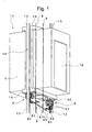
- Fig. 1 in an elevator shaft 1.1 movable elevator car referred to, which by means of a via a traction sheave guided carrying rope with a Counterweight is connected. Traction sheave, suspension rope and Counterweight are not shown.
- a cabin door 1.2 closes the elevator car 1.
- Guide rails 1.3 lead the elevator car 1 on their way.
- Speed limiter provided, with the movement the elevator car 1 or the counterweight by means of a Limiter ropes 6 on the speed limiter is transmitted.
- Speed limiter provided, with the movement the elevator car 1 or the counterweight by means of a Limiter ropes 6 on the speed limiter is transmitted.
- Speed limiter provided, with the movement the elevator car 1 or the counterweight by means of a Limiter ropes 6 on the speed limiter is transmitted.
- Speed limiter provided, with the movement the elevator car 1 or the counterweight by means of a Limiter ropes 6 on the speed limiter is transmitted.
- the centrifugal force principle or on the inertia principle limiter can also
- the governor rope 6 extends over the entire Schachthoehe and is at the lower end of the shaft by means of a Deflection pulley deflected and by means of a tensioning weight stretched and at the upper end of the shaft via a pulley of the speed limiter.
- the ends of the Beipporseiles 6 are at one of the elevator car. 1 arranged release mechanism 8 moored in an emergency a arranged on the elevator car 1 safety gear 9th actuated. At overspeed of the elevator car 1 in Down direction, the governor rope 6 is blocked, which an actuation of the trigger mechanism 8 has the result.
- the elevator car 1 is from a support frame 1.4 with a worn lower yoke 1.6 and an upper yoke 1.5, being the guided over the pulley, not shown Towing rope at one end with the upper yoke 1.5 and the other end connected to the counterweight, not shown.
- a Safety gear 9 arranged in emergency the Shut down elevator car 1.
- the elevator car 1 drives by means of the limiter 6, the sheave of Speed limiter on, at a certain Overspeed of the elevator car 1 in the downward direction the rope brake triggers and blocks.
- the rope brake and block the blocked speed limiter also about the arranged in the pit Guide roller guided limiter rope 6, the elevator car. 1 however, it continues to move down, with the blocked, connected to the release mechanism 8 limiter 6 the Catching device 9 engages.
- the standing with the governor rope 6 in connection Tripping mechanism 8 consists of axes of rotation 8.1 with Release lever 8.11, where the safety gear 9 engaging actuating lever 8.2 are arranged.
- the Rotary axis 8.1 of the operating lever 8.2 for the opposite safety gear 9 is by means of a the axis of rotation 8.1 arranged connecting rod 8.3 actuated.
- Fig. 2 shows the essential details of means Limiter rope 6 actuated release mechanism 8 for Engaging the safety gear 9.
- One at the lower yoke 1.6 arranged frame 1.61 has holes 1.611 on which the Attaching the safety gear 9 serve.
- Frame 1.61 a support 8.4 for the storage of the axis of rotation 8.1 by means of plates 8.43 and screws 8.44 on frame 1.61 arranged.
- Fig. 3 and Fig. 4 show details of the arrangement of Operating lever 8.2 at the axis of rotation 8.1.
- the Operating lever 8.2 has a long slot 8.21, the fits on the diameter of the axis of rotation 8.1, wherein the Operating lever 8.2 in the direction of the axis of rotation 8.1 and in Direction of the actuating lever 8.2 is freely movable.
- a Leg spring 8.5 keeps the operating lever 8.2 in the direction the axis of rotation 8.1 firmly.
- the one end of the spring 8.51 pushes the Operating lever 8.2 down, the movement of the Operating lever 8.2 by a lower stop 8.6 is limited.
- the other spring end 8.52 is detachable with the Carrier 8.4 connected.
- An upper stop 8.7 limits the Movement of the operating lever 8.2 upwards.
- the lower Stop 8.6 and the upper stop 8.7 are each a End held by a T-shaped Bride 8.8, with the Bride 8.8 is firmly connected to the axis of rotation 8.1.
- the The axis of rotation 8.1 is by means of sockets 8.9 on the carrier 8.4 stored.
- Fig. 4 is the automatic with arrows P1 Adjustment of the operating lever 8.2 to different Widths of the guide leg of the guide rail. 9 symbolizes.
- the operating levers 8.2 are in the direction of Rotary axis 8.1 against the spring force freely movable. In FIG. 3, not shown, is shown in FIG.
- Fig. 5 shows details of the attachment of the other Spring 8.52 on the beam 8.4.
- the carrier 8.4 has a T-shaped Recess 8.10 with a vertical and horizontal leg up.
- the leg spring 8.5 is preloaded, the spring end 8.52 from the horizontal leg of Recess 8.10 is held.
- By loosening the spring end 8.52 from the horizontal leg of the recess 8.10 is the Pretension of the leg spring 8.5 canceled.
- the one Spring end 8.51 can now be solved by the operating lever 8.2 and the operating lever 8.2 along the Long slot 8.21 backwards or in a recess 8.14 moved, if secured by means of pins 8.121 Locking pin 8.12 is removed. With pushed back Operating lever 8.2, the catch 9.1 is easy accessible.
- Fig. 6 shows the operating lever 8.2 in the starting position.
- the operating lever 8.2 are on the lower stop 8.6, wherein the firmly connected to the axis of rotation 8.1 Bridges 8.8 are pivoted downwards.
- Fig. 8 shows the Batrelinshebel 8.2 in the Friedausantsslage, in which the Briden 8.8 with the lower Stop 8.6 and the upper stop 8.7 in the Starting point are.
- the freely movable operating lever 8.2 are pivoted by an external force upwards with the movement through the upper stop 8.7 is limited.
- the Tethers 9.1 In the Freundausatesslage the Tethers 9.1 not engaged.
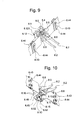
- Fig. 9 shows a variant of the Briden 8.8 with the lower stop 8.6 and without the upper stop 8.7. Without the upper stop 8.7, the deflection of the Actuator 8.2 not limited to the top.
- the Operating lever 8.2 is positively releasable with the Tether 9.1 connected. If a catch wedge 9.1 automatically engages, the associated operating lever is 8.2 after deflected above, without the rotational movement on the adjacent actuating lever 8.2 and the axis of rotation 8.1 is transmitted. This prevents the Connecting rod 8.3 is subjected to pressure. A Compressive stress would have a buckling of Connecting rod 8.3 result.
- Fig. 10 shows the contact plate 8.13 for monitoring the Position of the operating levers 8.2.
- the contact sheet is 8.13 along the support rear wall 8.45 by means of screws 8.15 the carrier rear wall 8.45 below the operating lever 8.2 arranged.
- On the support side wall 8.46 are holes 8.16 provided, the attachment of the Safety switch serve.
- Fig. 11 shows details of the device of FIG at least one carrier sidewall 8.46 is a Safety switch 8.17 using the holes 8.16 penetrating screws 8.18 arranged.
- the contact sheet 8.13 is by means of a cam 8.21 of the actuating lever 8.2 operated, the movement of the contact plate 8.13 is transmitted to the safety switch 8.17.
- Of the Safety switch 8.17 is activated if the Operating lever 8.2 along the long slot 8.21 is moved backwards or in the recess 8.14 or if the operating lever 8.2 is in the catch position.
Landscapes
- Engineering & Computer Science (AREA)
- Mechanical Engineering (AREA)
- Maintenance And Inspection Apparatuses For Elevators (AREA)
Abstract
Description
eine schematische Darstellung einer Aufzugskabine mit der erfindungsgemässen Einrichtung zur Stillsetzung der Aufzugskabine,
die wesentlichen Einzelheiten einer mittels Begrenzerseil betätigbaren Auslösemechanik zum Einrücken einer Fangvorrichtung,
Einzelheiten der Anordnung von Betätigungshebeln an einer Drehachse,
Einzelheiten der Befestigung eines Federendes an einem Träger,
die Betätigungshebel in der Ausgangslage,
die Betätigungshebel in der Fanglage,
die Batätigungshebel in der Fehlauslösungslage,
eine Ausführungsvariante der Auslösemechanik,
eine Einrichtung zur Überwachung der Lage der Betätigungshebel und
Einzelheiten der Einrichtung nach Fig. 10.
Claims (8)
- Einrichtung zum Einrücken einer Fangvorrichtung für eine Aufzugskabine bestehend aus einem, die Geschwindigkeit einer mittels Tragseil mit einem Gegengewicht verbundenen Aufzugskabine überwachenden Geschwindigkeitsbegrenzer, wobei die Bewegung der Aufzugskabine bzw. des Gegengewichtes mittels eines Begrenzerseiles auf den Geschwindigkeitsbegrenzer übertragen wird, der die Stillsetzung der Aufzugsanlage bei Übergeschwindigkeit auslöst, wobei eine mittels des Begrenzerseiles betätigbare Auslösemechanik vorgesehen ist, die die Fangvorrichtung einrückt,
dadurch gekennzeichnet, dass die Auslösemechanik (8) je Fangvorrichtung (9) eine Drehachse (8.1) aufweist, an der gegenüber der Drehachse (8.1) frei bewegliche Betätigungshebel (8.2) angeordnet sind, wobei die Betätigungshebel (8.2) beim Drehen der Drehachse (8.1) die Fangkeile (9.1) der Fangvorrichtung (9) betätigen. - Einrichtung nach Anspruch 1,
dadurch gekennzeichnet, dass der Betätigungshebel (8.2) einen Langschlitz (8.21) aufweist, der auf den Durchmesser der Drehachse (8.1) passt, wobei der Betätigungshebel (8.2) in Richtung der Drehachse (8.1) und in Richtung des Betätigungshebels (8.2) frei bewegbar ist. - Einrichtung nach den Ansprüchen 1 oder 2,
dadurch gekennzeichnet, dass zum Festhalten des Betätigungshebels (8.2) eine an der Drehachse (8.1) angeordnete Schenkelfeder (8.5) vorgesehen ist. - Einrichtung nach Anspruch 3,
dadurch gekennzeichnet, dass das eine Federende (8.51) lösbar am Betätigungshebel (8.2) und das andere Federende (8.52) lösbar an einem Träger (8.4) der Drehachse (8.1) angeordnet ist. - Einrichtung nach einem der vorhergehenden Ansprüche,
dadurch gekennzeichnet, dass zur Begrenzung der Bewegung des Betätigungshebels (8.2) nach unten ein unterer Anschlag (8.6) vorgesehen ist, wobei der untere Anschlag (8.6) an je einem Ende von einer T-förmigen Bride (8.8) gehalten wird, die fest mit der Drehachse (8.1) verbunden ist. - Einrichtung nach Anspruch 5,
dadurch gekennzeichnet, dass zur Begrenzung der Bewegung des Betätigungshebels (8.2) nach oben ein oberer Anschlag (8.7) vorgesehen ist, wobei der obere Anschlag (8.7) an je einem Ende von einer T-förmigen Bride (8.8) gehalten wird, die fest mit der Drehachse (8.1) verbunden ist. - Einrichtung nach einem der vorhergehenden Ansprüche,
dadurch gekennzeichnet, dass mindestens ein am Träger (8.4) angeordneter Sicherheitsschalter (8.17) vorgesehen ist, der die Lage des Betätigungshebels (8.2) überwacht. - Einrichtung nach Anspruch 7,
dadurch gekennzeichnet, dass die Bewegung des Betätigungshebels (8.2) auf ein Kontaktblech (8.13) übertragbar ist, das den Sicherheitsschalter (8.17) betätigt.
Priority Applications (1)
| Application Number | Priority Date | Filing Date | Title |
|---|---|---|---|
| EP03009103A EP1359111B1 (de) | 2002-05-02 | 2003-04-19 | Einrichtung zum Einrücken einer Fangvorrichtung für eine Aufzugskabine |
Applications Claiming Priority (3)
| Application Number | Priority Date | Filing Date | Title |
|---|---|---|---|
| EP02405356 | 2002-05-02 | ||
| EP02405356 | 2002-05-02 | ||
| EP03009103A EP1359111B1 (de) | 2002-05-02 | 2003-04-19 | Einrichtung zum Einrücken einer Fangvorrichtung für eine Aufzugskabine |
Publications (2)
| Publication Number | Publication Date |
|---|---|
| EP1359111A1 true EP1359111A1 (de) | 2003-11-05 |
| EP1359111B1 EP1359111B1 (de) | 2009-11-04 |
Family
ID=29217241
Family Applications (1)
| Application Number | Title | Priority Date | Filing Date |
|---|---|---|---|
| EP03009103A Expired - Lifetime EP1359111B1 (de) | 2002-05-02 | 2003-04-19 | Einrichtung zum Einrücken einer Fangvorrichtung für eine Aufzugskabine |
Country Status (1)
| Country | Link |
|---|---|
| EP (1) | EP1359111B1 (de) |
Citations (3)
| Publication number | Priority date | Publication date | Assignee | Title |
|---|---|---|---|---|
| JPH09240952A (ja) * | 1996-03-11 | 1997-09-16 | Toshiba Corp | エレベータの安全装置 |
| EP0841282A1 (de) * | 1996-11-11 | 1998-05-13 | Inventio Ag | Bremsauslösevorrichtung |
| JP2000219450A (ja) * | 1999-02-01 | 2000-08-08 | Toshiba Corp | エレベータ装置 |
-
2003
- 2003-04-19 EP EP03009103A patent/EP1359111B1/de not_active Expired - Lifetime
Patent Citations (3)
| Publication number | Priority date | Publication date | Assignee | Title |
|---|---|---|---|---|
| JPH09240952A (ja) * | 1996-03-11 | 1997-09-16 | Toshiba Corp | エレベータの安全装置 |
| EP0841282A1 (de) * | 1996-11-11 | 1998-05-13 | Inventio Ag | Bremsauslösevorrichtung |
| JP2000219450A (ja) * | 1999-02-01 | 2000-08-08 | Toshiba Corp | エレベータ装置 |
Non-Patent Citations (2)
| Title |
|---|
| PATENT ABSTRACTS OF JAPAN vol. 1998, no. 01 30 January 1998 (1998-01-30) * |
| PATENT ABSTRACTS OF JAPAN vol. 2000, no. 11 3 January 2001 (2001-01-03) * |
Also Published As
| Publication number | Publication date |
|---|---|
| EP1359111B1 (de) | 2009-11-04 |
Similar Documents
| Publication | Publication Date | Title |
|---|---|---|
| EP2771267B1 (de) | Geschwindigkeitsbegrenzer für einen aufzug | |
| EP2651808B1 (de) | Aufzugsanlage mit kabine und gegengewicht | |
| DE69416720T2 (de) | Verfahren und Einrichtung zum Auslösen eines Aufzugssicherheitsmechanismus | |
| EP2920101B1 (de) | Aufzug mit einer sicherheitsbremse | |
| DE60012792T2 (de) | Verfahren zum bremsen eines treibscheibenaufzugs | |
| EP0543154B1 (de) | Vorrichtung zum Auslösen von Sicherheitseinrichtungen | |
| EP2349900A1 (de) | Geschwindigkeitsbegrenzer für einen aufzug | |
| DE102012016336A1 (de) | Geschwindigkeitsbegrenzer für ein Aufzugsystem | |
| EP0440839A1 (de) | Vorrichtung zur Verhinderung unkontrollierter Bewegungen von Aufzügen | |
| EP2219983A1 (de) | Auffahrbremse für zwei unabhängig voneinander verfahrende aufzugkörper | |
| EP2125389A1 (de) | Aufzug | |
| EP2874933A1 (de) | Aufzugsanlage mit sicherheitsvorrichtung | |
| CH669181A5 (de) | Vorabschalteinrichtung an einem nockenrad-geschwindigkeitsbegrenzer fuer aufzuege. | |
| EP0787676A1 (de) | Sicherheitseinrichtung | |
| EP0980842B1 (de) | Einrichtung zur Stillsetzung einer Aufzugsanlage | |
| DE2400198A1 (de) | Sicherheitsbremse | |
| CH633495A5 (de) | Vertikale foerdereinrichtung mit fangvorrichtung. | |
| EP1350753B1 (de) | Einrichtung zum Einrücken einer Fangvorrichtung für eine Aufzugskabine | |
| DE102013215901A1 (de) | Servicelift | |
| EP1359111B1 (de) | Einrichtung zum Einrücken einer Fangvorrichtung für eine Aufzugskabine | |
| EP1447369B1 (de) | Einrichtung zum Einrücken einer Fangvorrichtung für eine Aufzugskabine | |
| EP3037375A1 (de) | Aufzugsanlage mit einem Halte- und Verstellsystem für eine Aufzugskabinenanordnung | |
| EP3020674B1 (de) | Servicelift | |
| EP3798174B1 (de) | Auslösevorrichtung für eine fangvorrichtung | |
| DE4313335C2 (de) | Schlitten mit Fallbremse |
Legal Events
| Date | Code | Title | Description |
|---|---|---|---|
| PUAI | Public reference made under article 153(3) epc to a published international application that has entered the european phase |
Free format text: ORIGINAL CODE: 0009012 |
|
| AK | Designated contracting states |
Kind code of ref document: A1 Designated state(s): AT BE BG CH CY CZ DE DK EE ES FI FR GB GR HU IE IT LI LU MC NL PT RO SE SI SK TR |
|
| AX | Request for extension of the european patent |
Extension state: AL LT LV MK |
|
| 17P | Request for examination filed |
Effective date: 20040421 |
|
| AKX | Designation fees paid |
Designated state(s): AT CH DE FR GB LI |
|
| R17C | First examination report despatched (corrected) |
Effective date: 20060620 |
|
| GRAP | Despatch of communication of intention to grant a patent |
Free format text: ORIGINAL CODE: EPIDOSNIGR1 |
|
| GRAS | Grant fee paid |
Free format text: ORIGINAL CODE: EPIDOSNIGR3 |
|
| GRAA | (expected) grant |
Free format text: ORIGINAL CODE: 0009210 |
|
| AK | Designated contracting states |
Kind code of ref document: B1 Designated state(s): AT CH DE FR GB LI |
|
| REG | Reference to a national code |
Ref country code: GB Ref legal event code: FG4D Free format text: NOT ENGLISH |
|
| REG | Reference to a national code |
Ref country code: CH Ref legal event code: EP |
|
| REF | Corresponds to: |
Ref document number: 50312081 Country of ref document: DE Date of ref document: 20091217 Kind code of ref document: P |
|
| PLBE | No opposition filed within time limit |
Free format text: ORIGINAL CODE: 0009261 |
|
| STAA | Information on the status of an ep patent application or granted ep patent |
Free format text: STATUS: NO OPPOSITION FILED WITHIN TIME LIMIT |
|
| 26N | No opposition filed |
Effective date: 20100805 |
|
| PG25 | Lapsed in a contracting state [announced via postgrant information from national office to epo] |
Ref country code: AT Free format text: LAPSE BECAUSE OF NON-PAYMENT OF DUE FEES Effective date: 20100419 |
|
| REG | Reference to a national code |
Ref country code: FR Ref legal event code: PLFP Year of fee payment: 14 |
|
| REG | Reference to a national code |
Ref country code: FR Ref legal event code: PLFP Year of fee payment: 15 |
|
| REG | Reference to a national code |
Ref country code: FR Ref legal event code: PLFP Year of fee payment: 16 |
|
| PGFP | Annual fee paid to national office [announced via postgrant information from national office to epo] |
Ref country code: FR Payment date: 20210427 Year of fee payment: 19 Ref country code: DE Payment date: 20210628 Year of fee payment: 19 |
|
| PGFP | Annual fee paid to national office [announced via postgrant information from national office to epo] |
Ref country code: CH Payment date: 20210422 Year of fee payment: 19 Ref country code: GB Payment date: 20210426 Year of fee payment: 19 |
|
| REG | Reference to a national code |
Ref country code: DE Ref legal event code: R119 Ref document number: 50312081 Country of ref document: DE |
|
| REG | Reference to a national code |
Ref country code: CH Ref legal event code: PL |
|
| GBPC | Gb: european patent ceased through non-payment of renewal fee |
Effective date: 20220419 |
|
| PG25 | Lapsed in a contracting state [announced via postgrant information from national office to epo] |
Ref country code: LI Free format text: LAPSE BECAUSE OF NON-PAYMENT OF DUE FEES Effective date: 20220430 Ref country code: GB Free format text: LAPSE BECAUSE OF NON-PAYMENT OF DUE FEES Effective date: 20220419 Ref country code: FR Free format text: LAPSE BECAUSE OF NON-PAYMENT OF DUE FEES Effective date: 20220430 Ref country code: DE Free format text: LAPSE BECAUSE OF NON-PAYMENT OF DUE FEES Effective date: 20221103 Ref country code: CH Free format text: LAPSE BECAUSE OF NON-PAYMENT OF DUE FEES Effective date: 20220430 |